PAGE 53A - Lincoln Industrial
PAGE 53A - Lincoln Industrial
PAGE 53A - Lincoln Industrial

Create successful ePaper yourself
Turn your PDF publications into a flip-book with our unique Google optimized e-Paper software.
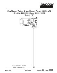
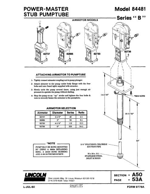
POWER-MASTER Model 84481<br />
STUB PUMPTUBE<br />
AIRMOTOR MODELS Series “B”<br />
ATTACHING AIRMOTOR TO PUMPTUBE<br />
1- Tightly connect airmotorcoupling nutto pump plunger.<br />
2- Attach airmotor to the pump outlet body flange with the four<br />
bolts and nuts (handtight) supplied with airmotor.<br />
3- Slowly cycle the pump several times, using just enough air<br />
pressure to operatethe pump withoutstalling.<br />
4- Stop the pump on an “up” stroke and tighten the four bolts &<br />
nuts to securelyfasten the airmotorto the pumptube.<br />
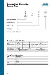
AIRMOTOR SELECTION<br />
Airmotor Diameter Series Ratio<br />
82737 2-1/2" 40 4:1<br />
82895 3" 56 61<br />
82730 4-1/4” 115 12:1<br />
82736 6" 225 24:1<br />
*NOTE<br />
PUMP MAY BE BUNG MOUNTED<br />
BY USING A69894 RETAINING<br />
RING, A40430 BUNG BUSHING<br />
AND A66130 THUMB SCREW.<br />
LINCOLN One <strong>Lincoln</strong> Way St. Louis Missouri 63120-1578<br />
L-JUL-80<br />
(314) 679-4200 Telex 44887<br />
SECTION - A50<br />
<strong>PAGE</strong> - <strong>53A</strong><br />
Copyright 1987<br />
Printed in U.S.A. FORM 9778A
© Indicates change<br />
DISASSEMBLY INSTRUCTIONS<br />
Unscrew 15783 Foot Valve Body from 93360<br />
Pump Tube Assembly. 16166 Plunger Rod and<br />
93405 Piston Assembly should drop out through<br />
bottom of pump tube.<br />
To remove plunger rod from piston assembly,<br />
place the plunger rod in a vise on wrench flats.<br />
Loosen piston assembly using 7/8” wrench on<br />
wrench flats. To replace 34796 U-cup Packing,<br />
loosen two 50550-9 Set Screws and remove<br />
16322 Retainer.<br />
To replace 70271 Bushing and 48601-9 Washer,<br />
Refer to Fig. 2 on back page. (93405 Piston is<br />
complete with 70271 Bushing and 48601-9<br />
Washer.)<br />
After removing two 16321 Pins and 69796 Ball,<br />
Refer to Fig. 3 on back page to replace 16319-9<br />
Check Insert and 34550 O-rings.<br />
Remove 69277-9 Retaining Ring and 16320<br />
Spacer to replace 70257 Bushing and 34795 U-cup<br />
Packing in gland.<br />
SERVICE PARTS<br />
PART QUAN. DESCRIPTION PART QUAN. DESCRIPTION<br />
15783 1 Foot valve body 34796 1 U-cup (Buna-N)<br />
16044-9 1 Ball Stop 48629-9 1 Washer<br />
16166 1 Plunger rod 50550-9 2 Set screw<br />
16318-9 1 Check seat 67433 1 Extension pipe<br />
16319-9 1 Check insert 68908-9 1 Retaining ring<br />
16320 1 Spacer 69277-9 1 Retaining ring<br />
16321 2 Pin 69793 1 Ball<br />
16322 1 Retainer 69796 1 Ball<br />
34309 1 O-ring 70257 1 Bushing<br />
34316 1 O-ring 70330 1 Strainer<br />
34550 2 O-ring 93360 1 Pump tube assembly<br />
34795 1 U-cup (Buna-N) 93405 1 Piston assembly<br />
SEAL *BUNA-N POLYURETHANE<br />
ROD 34795 34401<br />
PISTON 34796 34479<br />
*Recommended for wash pump applications.<br />
Lubricate I.D. ofBushing,<br />
I.D. &O.D. ofU-cup Packing<br />
with light grease.<br />
Lubricate<br />
U-cup Packing<br />
& Bushing O.D.<br />
with light grease.<br />
Fig. 1<br />
ASSEMBLY INSTRUCTIONS<br />
1. Install U-cup Packing and<br />
Bushing in top of Pump Tube<br />
and secure with Retaining<br />
Ring.<br />
IMPORTANT:<br />
Do not hold flange in vise<br />
when removing or installing<br />
foot valve body. Hold tube in<br />
vise just under flange - outlet<br />
boss will prevent rotation.<br />
4. Lubricate internal chamfer<br />
above threads with light<br />
grease before inserting<br />
Plunger Rod and Piston<br />
Assembly.<br />
5. Carefully guide Plunger Rod<br />
and Piston Assembly up<br />
through bottom of pump tube<br />
to prevent damage to<br />
packings.<br />
2.<br />
Assemble Ball Stop to Plunger<br />
Rod. Plunger Rod-can be held<br />
in a vise on wrench flats.<br />
3.Connect Piston Assembly to<br />
Plunger Rod using a 1" socket.<br />
TORQUE TO<br />
55 FT. LBS.
Fig. 2<br />
TO REPLACE<br />
48601-9 WASHER & 70271 BUSHING<br />
TO REPLACE<br />
16319-9 CHECK INSERT & 34550 O-RINGS<br />
Fig. 3<br />
Invert 15783 Foot Valve Body and place on hard, flat<br />
surface. Tap 16319-9 Check Insert out using 7/8” Dia.<br />
aluminum or brass rod. New check insert should be tapped<br />
in with 1” or larger aluminum or brass rod.<br />
RETAIN THIS INFORMATION FOR FUTURE REFERENCE<br />
When ordering replacement parts, list: Part Number, Description, Model Number, and Series Letter.<br />
LINCOLN provides a Distributor Network that stocks equipment and replacement parts.<br />
A list of Authorized Service Departments will be furnished upon request.