Republic P-47D Thunderbolt Instructions - Testors
Republic P-47D Thunderbolt Instructions - Testors
Republic P-47D Thunderbolt Instructions - Testors

Create successful ePaper yourself
Turn your PDF publications into a flip-book with our unique Google optimized e-Paper software.
<strong>Republic</strong> P-<strong>47D</strong> <strong>Thunderbolt</strong> <strong>Instructions</strong><br />
>' «•, „«•; •*..* * , *,/,<br />
,5 * v<br />
f'V''*, , '', *' ?;';s,»' x *<br />
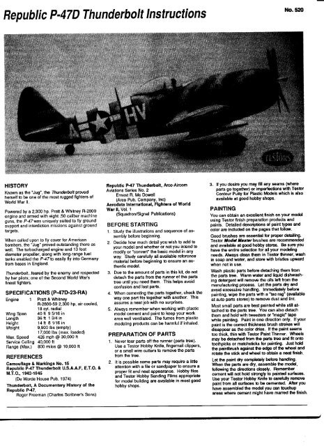
HISTORY<br />
Known as the "Jug", the <strong>Thunderbolt</strong> proved<br />
herself to be one of the most rugged fighters of<br />
World War II.<br />
Powered by a 2,300 hp. Pratt & Whitney R-2800<br />
engine and armed with eight .50 caliber machine<br />
guns, the P-47was uniquely suited to fly ground<br />
support and interdiction missions against ground<br />
targets.<br />
When called upon to fly cover for American<br />
bombers, the "Jug" proved outstanding there as<br />
well. The turbocharged engine and 13 foot<br />
diameter propeller, along with long-range fuel<br />
tanks enabled the P-47 to easily fly into Germany<br />
from bases in England.<br />
<strong>Thunderbolt</strong>...feared by the enemy and respected<br />
by her pilots; one of the Second World War's<br />
finest fighters.<br />
SPECIFICATIONS (P-<strong>47D</strong>-23-RA)<br />
Engine 1 Pratt & Whitney<br />
R-2800-59 2,300 hp, air cooled,<br />
18 cyl. radial<br />
Wing Span 40ft 9 5/16 in<br />
Length 36 ft 1 3/4 in<br />
Height 14 ft 8 1/16 in<br />
Weight 9,900 Ibs (empty)<br />
17,000 Ibs (max. loaded)<br />
Max. Speed 426 mph @ 30,000 ft<br />
Service Ceiling 40,000 ft<br />
Range (Max.) 800 miles @ 10,000 ft<br />
REFERENCES<br />
Camouflage & Markings No. 15<br />
<strong>Republic</strong> P-47 <strong>Thunderbolt</strong> U.S.A.A.F, E.T.O. &<br />
M.T.O., 1942-1945<br />
(De Worde House Pub. 1974)<br />
<strong>Thunderbolt</strong>, A Documentary History of the<br />
<strong>Republic</strong> P-47,<br />
Roger Freeman (Charles Scribner's Sons)<br />
<strong>Republic</strong> P-47 <strong>Thunderbolt</strong>, Arco-Aircorn<br />
Aviations Series No. 2<br />
Ernest R. Me Dowell<br />
(Arco Pub. Company, Inc)<br />
Aerodata International, Fighters of World<br />
War II, Vol. 1<br />
(Squadron/Signal Publications)<br />
BEFORE STARTING<br />
1. Study the illustrations and sequence of assembly<br />
before beginning.<br />
2. Decide how much detail you wish to add to<br />
your model and whether or not you intend to<br />
modify or "convert" the basic model in any<br />
way. Study carefully all available reference<br />
material before beginning to ensure an authentic<br />
model.<br />
3. Due to the amount of parts in this kit, do not<br />
detach the parts from the runner of the parts<br />
tree until you need them. This helps avoid<br />
confusion and lost parts.<br />
4. When cementing the parts together, check the<br />
way one part fits together with another. This<br />
assures a neat job with no surprises.<br />
5. Always remember when working with plastic<br />
model cement and paint to keep your work<br />
area well ventilated. The fumes from plastic<br />
modeling products can be harmful if inhaled.<br />
PREPARATION OF PARTS<br />
1. Never tear parts off the runner (parts tree).<br />
Use a Testor Hobby Knife, fingernail clippers,<br />
or a small wire cutters to remove the parts<br />
from the tree.<br />
2. It is possible some parts may require a little<br />
attention with a file or sandpaper to ensure a<br />
proper fit and neat appearance. Hobby files<br />
and Testor Hobby Sanding Films appropriate<br />
for model building are available in most good<br />
hobby shops.<br />
No. 520<br />
3. If you desire you may fill any seams (where<br />
parts go together) or imperfections with Tester<br />
Contour Putty for Plastic Models which is also<br />
available at good hobby shops.<br />
PAINTING<br />
You can obtain an excellent finish on your model<br />
using Testor finish preparation products and<br />
paints. Detailed descriptions of paint types and<br />
color are included on the pages that follow.<br />
Good brushes are essential for proper detailing.<br />
Testor Model Master brushes are recommended<br />
and available at good hobby stores. Be sure you<br />
have the entire selection for all your modeling<br />
needs. Always dean them in Testor thinner, wash<br />
in soap and water, and store with bristles upward<br />
when not in use.<br />
Wash plastic parts before detaching them from<br />
the parts tree. Warm water and liquid dishwashing<br />
detergent will remove the oils left from the<br />
manufacturing process. Let the parts dry and<br />
avoid excessive handling. Immediately before<br />
painting, wipe the parts with a "tac rag" (available<br />
at auto parts stores) to remove dust and lint.<br />
Most small parts are best painted while still attached<br />
to the parts tree. You can also detach<br />
them and hold with tweezers or "magic" tape<br />
while painting. Paint in one direction only. If your<br />
paint is the correct thickness brush strokes will<br />
disappear as the color dries. If the paint seems<br />
too thick, thin with Testor Paint Thinner. Wheels<br />
may be detached from the parts tree and fit onto<br />
toothpicks or matchsticks for painting. Just hold<br />
the paintbrush against the edge of the wheel and<br />
rotate the stick and wheel to obtain a neat finish.<br />
Let the paint dry completely before handling.<br />
When the parts are dry, assemble the model,<br />
following the directions closely. Remember<br />
cement will not hold strongly to painted surfaces.<br />
Use your Testor Hobby Knife to carefully remove<br />
paint from all surfaces to be cemented. After you<br />
have assembled the model you can touchup<br />
areas where cement might have marred the finish.
Tweezers will be useful in assembling the<br />
many small parts in this kit. The type used<br />
by postage stamp collectors is recommended.<br />
Your P-<strong>47D</strong> model may be built as either a<br />
Bubbletop or a Razorback version. One<br />
decal marking and color scheme has been<br />
selected for each version. Consult the<br />
drawings on pgs. 6 and 7 and box top photos<br />
to decide which version you prefer before<br />
proceeding.<br />
1 SUBASSEMBLIES<br />
Preliminary Painting<br />
Paint parts as indicated by Italic letter<br />
callouts using the COLOR KEY on pg. 3.<br />
Assembly<br />
1. Cement drop tank halves 44A, 44B and<br />
45A, 45B together making two tanks.<br />
Glue bomb halves B42 and B43<br />
together. Cement seat B7 to pilot's<br />
armor plate B6 as shown. If you are<br />
building the Razorback version, cut or<br />
break off the headrest portion of B6<br />
along the scored line. Glue propeller<br />
hub halves 31 and 32 together.<br />
2. Cement tailwheel tire B24 to tailwheel<br />
strut 23. Slip (do not cement) one tire<br />
B18 over axle on each landing gear<br />
strut 16 and 17 and fasten by carefully<br />
gluing one wheel hub 19 to the protuding<br />
tip of each axle. Do not allow<br />
glue to touch tires or they will not roll.<br />
Malngear<br />
(left side shown)<br />
The Testor Model Master paint system is<br />
specially designed to be used on military<br />
models. The Preliminary Painting instructions<br />
on this sheet indicate which Model<br />
Master colors to use as indicated by name<br />
and Federal Standard (FS) number. These<br />
colors are called out by bold Italic type.<br />
Wherever Model Master colors are not<br />
applicable the required Testor color will be<br />
called out by number and name in regular<br />
bold type.<br />
Drop Tanks<br />
make 2<br />
446 (45B)<br />
Pilot's Seat<br />
B7<br />
Note: Part numbers in parentheses () are<br />
for a second or opposite assembly.<br />
44A (45A)<br />
Cor D<br />
remove for<br />
""L—•- Razorback<br />
version only<br />
B6<br />
Liquid cement, Testor #3502, is recommended<br />
for construction since it can produce<br />
the neatest, quickest, and strongest glue<br />
joints. Apply small amounts of cement,<br />
using the tip of a Testor Model Master No.<br />
2 brush, to the surfaces to be joined while<br />
holding the parts in place. Do not use large<br />
amounts of cement.<br />
Tailwheel<br />
C :fuae<br />
Bomb<br />
B42<br />
B43<br />
Propeller Hub<br />
31<br />
» B24<br />
L :atripes<br />
E -.overall
No. 520<br />
fm FUSELAGE/ENGINE<br />
Preliminary Painting<br />
Paint parts as indicated by Italic letter<br />
callouts using the COLOR KEY below.<br />
Assembly<br />
1. Cement cockpit floor B2 to projecting<br />
pins between locators inside right<br />
fuselage half 7. Note: Pin at rear of<br />
floor should project upwards. Cement<br />
tab at bottom of pilot armor plate into<br />
slot in floor. Glue left fuselage half 3 to<br />
right fuselage half 7. Cement turbine<br />
exhaust/tailwheel well panel 25 into slot<br />
on underside of fuselage.<br />
2. Cement intake lip 29 inside cowling 28<br />
as shown. Slip (do not cement)<br />
propeller hub into pitch jig B34 with<br />
flange side facing up. Glue pins on<br />
propeller blades B33 into sockets on<br />
hub and gently twist blades in direction<br />
indicated until trailing edge of blades<br />
touch flange on pitch jig. Set propeller<br />
assembly aside to dry.<br />
3. Cement engine B30 into backside of<br />
cowling, making sure that key in top of<br />
cowling fits into notch at top of engine.<br />
Slip (do not cement) propeller shaft into<br />
hole in front of crankcase and fasten in<br />
place by carefully cementing retainer<br />
hub B35 into projecting portion of<br />
propeller shaft. Do not allow glue to<br />
touch engine or propeller will not rotate.<br />
COLOR KEY<br />
A No. 1749 Flat Black FS 37038<br />
B No. 1715 Interior Green FS 34151<br />
C No. 1790 Chrome Silver FS 17178<br />
D No. 1725 Neutral Gray FS 36270<br />
E No. 1711 Olive Drab FS 34087<br />
F No. 1704 Armor Sand FS 30277<br />
G No. 1768 Flat White FS 37875<br />
H No. 1138 Gray<br />
J No. 1147 Black<br />
K No. 1150 Flat Red<br />
L No. 1169 Flat Yellow<br />
M No. 1170 Flat Light Tan<br />
N No. 1180 Steel<br />
P No. 1183 Rubber<br />
Fuselage Assembly<br />
Engine Cowling AMwnbly<br />
29<br />
B<br />
Preliminary Painting<br />
Crankcase B30<br />
A :magnetoa<br />
A -.backing plate<br />
N -.engine cylinders<br />
J :pushrods<br />
H -.crankcaie<br />
crankcase<br />
B30<br />
25
\J WINGS /FUSELAGE<br />
Preliminary Painting<br />
Paint parts as indicated by italic letter<br />
callouts using the COLOR KEY on below.<br />
Assembly<br />
1. Cement left landing gear strut<br />
assembly into locating lugs inside left<br />
lower wing 15. Note that oleo scissor<br />
faces forward and spoked wheel hub<br />
faces Inward. Glue machine gun<br />
barrels B20 to position shown in drawing<br />
making sure that B20 butts against rib<br />
inside lower wing. Cement upper wing<br />
half 22 to lower wing half 15. Repeat<br />
procedure for right wing using lower<br />
wing half 14, right gear strut assembly,<br />
machine guns B20 and upper wing<br />
half 21.<br />
2. Cement left and right stabilizers 27 and<br />
26 into slots on either side of rear<br />
fuselage as shown. Make sure that<br />
stabilizers are lined up correctly.<br />
Cement left and right wings to fuselage.<br />
Glue engine cowling assembly to front<br />
of fuselage. Again, check cowling,<br />
wings and stabilizers to make sure they<br />
all line up straight, then set aside to dry.<br />
COLOR KEY<br />
A No. 1749 Flat Black FS 37038<br />
B No. 1715 Interior Green FS 34151<br />
C No. 1790 Chrome Silver FS 17178<br />
D No. 1725 Neutral Gray FS 36270<br />
E No. 1711 Olive Drab FS 34087<br />
F No. 1704 Armor Sand FS 30277<br />
G No. 1768 Flat White FS 37875<br />
H No. 1138 Gray<br />
J No. 1147 Black<br />
K No. 1150 Flat Red<br />
L No. 1169 Flat Yellow<br />
M No. 1170 Flat Light Tan<br />
N No. 1180 Steel<br />
P No. 1183 Rubber<br />
Wings<br />
Left Wing shown<br />
scissor<br />
faces<br />
forward<br />
Wings/Engine Cowling/Fuselage<br />
Note: part numbers in parentheses ()<br />
are for right wing assembly<br />
left strut assembly<br />
(right - opposite assembly)<br />
22 (21)<br />
15(14)
No. 520 P-<strong>47D</strong> <strong>Thunderbolt</strong><br />
Votre modele P-<strong>47D</strong> peut etre construit en version Bubbletop ou Razorback. Les decalcomanies et les<br />
couleurs ont ete selectionnees pour chacun des modeles. Avant de commencer, se reporter aux dessins<br />
des pages 6 et 7 ainsi qu'aux photos situees sur la boTte pour decider quelle version vous preferez.<br />
1SOUS ASSEMBLAGE<br />
Peinture preliminaire<br />
Peindre les pieces en suivant les indications en italique dans la LISTE DES COULEURS situee a la page 3.<br />
Assemblage<br />
1. Coller les moities de reservoir 44A - 44B et 45A - 45B ensemble pour obtenir deux reservoirs. Coller les moities de bombe<br />
B42 et B43 ensemble. Coller le siege B7 sur la plaque armee B6 comme indique. Si vous construisez la version Razorback,<br />
ouper ou casser la partie repose-tete de B6 en suivant le trait grav6. Coller les moiti6s du moyeu de I'h6lice 31 et 32.<br />
2. Coller le pneu de la roue arriere B24 sur la jambe de la roue 23. Glisser (ne pas coller) un pneu B18 sur I'essieu de chaque<br />
ambe de train d'atterrissage 16 et 17 et immobiliser le tout en collant soigneusement un moyeu de roue 19 sur I'extremite de<br />
essieu qui depasse. Ne pas mettre de code sur les roues, cela les empecherait de tourner.<br />
Remarque : Les numeros de piece entre parentheses () concernent le deuxieme montage sur le cote oppos6.<br />
Drop tanks make 2 = 2 reservoirs largables<br />
Bomb = Bombe<br />
Overall = General<br />
Stripes = Traits<br />
Fuse = Fuse<br />
Pilot's seat = Siege du pilote<br />
Maingear (left side shown) = Train principal (cote gauche illustre)<br />
Tailwheel = Roue arriere<br />
Propeller hub = Moyeu de I'helice<br />
Remove for Razorback version only = Retirer pour la version Razorback seulement.<br />
2 FUSELAGE / MOTEUR<br />
Peindre les pieces en suivant les indications en italique dans la LISTE DES COULEURS situee ci-dessous.<br />
Assemblage<br />
1. Coller le sol du cockpit B2 sur les tiges qui depassent & I'interieur du fuselage droit, moiti6 7. Remarque : La tige situ6e a I'ariere<br />
du sol du cockpit doit pointer vers le haut. Coller la languette situee au bas de la plaque armee du pilote dans la fente<br />
ituee dans le sol. Coller la moitie gauche du fuselage 3 a la moitie droite 7. Coller la turbine d'echappement et le puits de la<br />
oue arriere 25 dans la fente situee sous le fuselage.<br />
2. Coller la levre d'entree d'air 29 a I'interieur du capot moteur 28 comme indique. Glisser (ne pas coller) le moyeu de I'helice<br />
dans le pitch jig B34 semelle vers le haut. Coller les tiges des pales de I'helice B33 dans les emboTtures situees sur le moyeu<br />
ourner doucement les pales dans le sens indique jusqu'a ce que le bord de fuite des pales touchent la semelle au niveau du<br />
pitch jig . Laisser secher I'helice.<br />
3. Coller le moteur B30 dans I'arriere du capot moteur, en vous assurant que la c!6 situee en haut du capot moteur s'encastre<br />
dans I'encoche situee en haut du moteur. Glisser (ne pas coller) I'arbre de I'helice dans I'orifice situe a I'avant du carter et serrer<br />
ensemble en collant soigneusement le moyeu de retenue B35 a la partie de I'arbre de I'helice qui depasse. Ne pas mettre de<br />
olle sur le moteur, sinon I'helice ne tournera pas.
LISTE DES COULEURS<br />
A No. 1749 NoirFS 37038<br />
B No. 1715 Vert interieur FS 34151<br />
C No. 1790 Chrome argent FS 17178<br />
D No. 1725 GrisneutreFS 36270<br />
E No. 1711 Kaki FS 34087<br />
F No. 1704 Sable FS 30277<br />
G No. 1768 Blanc FS 37875<br />
H No. 1138Gris<br />
No. 1147Noir<br />
K No. 1150 Rouge<br />
L No. 1169Jaune<br />
M No. 1170 Blanc casse<br />
N No. 1180 Metallise<br />
P No. 1183 Caoutchouc<br />
Fuselage assembly = Assemblage du fuselage<br />
Pilot's seat assembly = Assemblage du siege du pilote<br />
nside = Interieur<br />
Engine cowling assembly = Assemblage du capot moteur<br />
Hub assembly = Assemblage du moyeu<br />
Blades = Pales<br />
Tips = Extremites<br />
Preliminary painting Crancase B30 = Peinture preliminaire du carter B30<br />
Magnetos = Magnetos<br />
Engine cylinders = Cylindres du moteur<br />
Pushrods= Tiges de culbuteur<br />
Crankcase = Carter<br />
Backing plate = Plaque d'appui<br />
Crankcase = Carter<br />
3 AILES / FUSELAGE<br />
Peindre les pieces en suivant les indications en italique dans la LISTE DES COULEURS situee ci-dessous.<br />
Assemblage<br />
1. Coller la jambe du train d'atterrissage gauche dans les oreilles de centrage situees dans I'aile inferieure gauche 15. Veuillez<br />
noter que I'oleo scissor est situe a I'avant et que le moyeu de la roue a rayons est vers Pinterieur. Coller les cylindres des<br />
mitrailleuses B20 dans la position indiquee par le dessin en vous assurant que B20 bute contre la cannelure a I'interieur de I'aile<br />
nferieure. Coller la moitie superieure de I'aile 22 a la moitie inferieure de I'aile 15. Faire la merme operation pour I'aile droite a<br />
aide de la moitie d'aiie inferieure 14, de la jambe du train d'atterrissage droit B20 et de la moitie d'aile superieure 21.<br />
2. Coller les stabilisateurs gauche et droite 27 et 26 dans les fentes situes de part et d'autre du fuselage arriere comme illustre.<br />
S'assurer que les stabilisateurs soient correctement alignes. Coller les ailes droite et gauche contre le fuselage. Coller le capot<br />
moteur sur I'avant du fuselage. Verifier a nouveau si le capot moteur, les ailes et les stabilisateurs sont bien alignes puis laisser<br />
echer.<br />
Wings = Ailes<br />
Left wing shown = Aile gauche illustree<br />
Note : part number in parentheses () are for right wing assembly = Remarque : Les numeros de piece entre<br />
parentheses () concement I'aile droite<br />
nterior of wheel wells = Interieur des puits de roues<br />
Gun barrels = Cylindres des mitrailleuses<br />
Scissor faces forward - Scissor oriente vers I'avant<br />
Left strut assembly (right = opposite assembly) = Assemblage de la jambe gauche (droite = assemblage du<br />
cote oppose). Wings / Engine Cowling / Fuselage = Ailes / Capot moteur / Fuselage<br />
Engine cowling assembly = Assemblage du capot moteur
Remarque : Les pieces en plastique transparent collent mieux avec la colle blanche. Celle-ci ne ternit<br />
pas le plastique et le resultat obtenu est plus joli qu'avec une colle ordinaire pour modeles<br />
reduits.<br />
4 Assemblage de la verriere<br />
Peindre les pieces en suivant les indications en italique dans la LISTE DES COULEURS situee a la page 4.<br />
Assemblage<br />
1. Version Bubbletop seulement: Coller la decalcomanie des instruments 1 sur le tableau de bord B5. Coller le tableau de bord<br />
ur les tiges situees dans la partie inferieure de I'encadrement du pare-brise du cockpit 4. Coller I'encadrement du pare-brise du<br />
ockpit au haut du fuselage. Coller le pilote dans son siege (optionnel). Coller le pare-brise sur la partie plate a I'avant du cockpit.<br />
Coller la verriere sur le cadre prevu a cet effet 11, puis coller I'encadrement du pare-brise du cockpit en position ouverte ou<br />
ermee. Coller I'antenne radio B41 sur le dos du fuselage.<br />
1. Version Razorback seulement: Coller la decalcomanie des instruments 1 sur le tableau de bord B5. Coller le carenage 48 a<br />
arriere de I'ouverture du cockpit dans I'encadrement du pare-brise du cockpit 4A. Coller le tableau de bord B5 sur les tiges<br />
ituees dans la partie inferieure de I'encadrement du pare-brise. Coller I'encadrement du pare-brise du cockpit en haut du fuseage.<br />
Coller la vitre pare-balles dans la fente situee a I'avant du cockpit. Coller le pilote dans son siege (optionnel). Coller le parebrise<br />
sur la partie plate a I'avant du cockpit. Coller la verriere en position ouverte ou fermee. Coller I'antenne radio B41 sur le<br />
dos du fuselage. y<br />
Remarque : II est plus facile de peindre et d'apposer les decalcomanies si les equipements destines aux ailes et/ou les armes<br />
ne sont pas encore colles,<br />
5 ASSEMBLAGE FINAL<br />
Peindre les pieces en suivant les indications en italique dans la LISTE DES COULEURS situee a la page 4.<br />
Assemblage<br />
1. Coller la roue arriere (a partir de I'etape 1) dans I'embofture a cote du puits a roue. Coller les trappes principals des trains<br />
d'atterrissage droit et gauche 36 et 37 sur leurs jambes de trains d'atterrissage respectifs. Coller les trappes interieures droite et<br />
gauche 38 et 39 sur le bord interieur des puits a roues comme illustre.<br />
2. Coller une des lumieres de navigation sur I'entaille situee a chaque extremite d'aile. Coller le tube du pilote B40 dans I'orifice<br />
itue dans le bord d'attaque de I'aile gauche. Coller la bombe (a partir de I'etape 1) dans I'orifice prevu a cet effet dans le bas du<br />
uselage. Coller un reservoir largable (a partir de I'etape 1) dans les orifices prevus a cet effet dans les pylones situes sous les<br />
ailes.<br />
3. Votre modele est maintenant termine. Vous pouvez maintenant y appliquer les decalcomanies restantes et effectuer les<br />
dernieres finitions.<br />
Bubbletop = Bubbletop<br />
Frames = Cadres<br />
Canopy = Verriere<br />
nterior = Interieur<br />
Windscreen = Pare-brise<br />
Razorback = Razorback<br />
Frames = Cadres<br />
Canopy = Verriere<br />
nterior = Interieur<br />
Windscreen = Pare-brise<br />
Bulletproof glass = Vitre pare-balles<br />
Remove (Razorback only) = Retirer (Modele Razorback seulement)
Red = Rouge<br />
Lens = Lumiere<br />
Drop tank = Reservoir largable<br />
Bomb.- Bombe<br />
nside - Interieur<br />
Tailwheel = Roue arriere<br />
Drop tank ~ Reservoir largable<br />
Green = Vert<br />
Lens = Lumiere<br />
P-<strong>47D</strong>, 61 erne Escadron de Combat, 56eme Groupe de Combat, Seme Air Force; Boxted, R.U. Pilote par<br />
des pilotes chevronnes tels que le Lt. Col. Francis E. Gabreski avec 28 victoires a son actif, chiffre plus tard<br />
evue a la hausse avec 31 victoires.<br />
LISTE DES COULEURS<br />
FS38118Grisbataille<br />
FS 36440 Gris mouette<br />
FS 17178 Chrome argent<br />
FS 37038 Noir<br />
FS 37875 Blanc<br />
No. 1150 Rouge<br />
REMARQUE = Pas de decalcomanie 18 en forme de bande noire<br />
Chrome silver) = (Chrome argent)<br />
Red = Rouge<br />
Green = Vert<br />
Les chiffres renvoient a des decalcomanies. Voir APPLICATION DES DECALCOMANIES a la page 8.<br />
Yellow = Jaune<br />
Green = Vert<br />
Red = Rouge<br />
P-<strong>47D</strong>, 302eme Escadron de Combat, 332eme Groupe de Combat, 15eme Air Force. Site operaionnel<br />
en Mediterranee en 1944.<br />
Voir la section des QUEUES ROUGES a la page 8 pour connaTtre I'historique.<br />
LISTE DES COULEURS<br />
FS 17178 Chrome argent<br />
FS 37038 Noir<br />
No. 1150 Rouge<br />
Les chiffres renvoient a des decalcomanies. Voir APPLICATION DES DECALCOMANIES a la page 8.<br />
Yeljow= Jaune<br />
Green = Vert<br />
Red = Rouge<br />
*
No. 520<br />
Note: Clear parts are best glued in place<br />
with white glue. White glue will not mar the<br />
plastic and thus results in a better appearance<br />
than conventional model cement.<br />
*T CANOPY ASSEMBLY<br />
Preliminary Painting<br />
Paint parts as indicated by Italic letter<br />
callouts using the COLOR KEY on pg. 4.<br />
Assembly<br />
1. Bubbletop version only: Apply<br />
instrument panel decal 1 to instrument<br />
panel B5. Cement instrument panel to<br />
pins in underside of cockpit coaming 4.<br />
Glue cockpit coaming to top of fuselage.<br />
Cement pilot into seat (optional). Glue<br />
windscreen to flat portion at front of<br />
cockpit. Glue canopy to canopy frame<br />
11, then cement to cockpit coaming in<br />
either open or closed position. Cement<br />
radio mast B41 to notch to fuselage<br />
spine.<br />
2. Razorback version only: Apply instrument<br />
panel decal 1 to instrument panel<br />
B5. Cement fairing 48 to rear of cockpit<br />
opening in cockpit coaming 4A. Glue<br />
instrument panel B5 to pins in underside<br />
of coaming. Cement coaming to top of<br />
fuselage. Glue bulletproof glass into<br />
slot of front cockpit. Cement pilot to<br />
seat (optional). Glue windscreen to flat<br />
portion ahead of cockpit. Glue canopy<br />
in place in either open or closed<br />
position. Cement radio mast to B41 to<br />
notch on fuselage spine.<br />
Note: It may be easier to paint and decal<br />
your model if underwing stores and/or<br />
armament are left off until model is completely<br />
finished.<br />
%/ FINAL ASSEMBLY<br />
Preliminary Painting<br />
Paint parts as indicated by italic letter<br />
callouts using the COLOR KEY on pg. 4.<br />
Assembly<br />
1. Cement tailwheel assembly (from Step<br />
1) into socket inside rear wheel well.<br />
Glue right and left main landing gear<br />
doors 36 and 37 to right and left main<br />
gear struts respectively. Cement right<br />
and left inner gear doors 38 and 39 to<br />
inner edge of wheel wells as shown.<br />
2. Glue one navigation light lens to the<br />
notch located in each wingtip. Cement<br />
pitot tube B40 into hole in leading edge<br />
of left wing. Glue bomb (from Step 1)<br />
into hole on belly of fuselage. Cement<br />
one drop tank (from Step 1) into holes<br />
in each underwing pylon.<br />
3. Construction of your model is now<br />
complete. It is now ready for application<br />
of remaining decals and final finishing.<br />
Bubbletop<br />
frames: C,<br />
windscreen<br />
Final Assembly<br />
lens<br />
Razorback<br />
bulletproof glass<br />
windscreen<br />
remove (Razorback only)<br />
frames: C<br />
bomb<br />
canopy<br />
canopy<br />
B -.inside<br />
drop tank tailwheel<br />
lens
P-<strong>47D</strong>, 61 at Fighter Squadron, 56th Fighter Group,<br />
8th Air Force; Boxted, U.K. Flown by top ace<br />
Lt. Col. Francis E. Gabreskl, with 28 victories,<br />
later Increased to 31.<br />
COLOR KEY<br />
HH FS 36118 Gunshlp Gray<br />
I | FS 36440 Flat Gull Gray<br />
FS 17178 Chrome Silver<br />
FS 37038 Flat Black<br />
FS 37875 Flat White<br />
No. 1150 Flat Red<br />
NOTE: No black stripe decal 18.<br />
16<br />
(chrcmu slhffr)<br />
Numbers indicate decal elements.<br />
See APPLYING DECALS on page 8.<br />
NOTE: No black stripe decal 18.<br />
NOTE: No black stripe decal 18
NO.520<br />
yellow<br />
yellow<br />
yellow<br />
17 12<br />
P-<strong>47D</strong>, 302nd Fightar Squadron, 332nd Fighter Group,<br />
15th Air Force; Mediterranean Theater of Operations,<br />
1944.<br />
yellow See THE RED TAILS section on page 8 for<br />
historical background.<br />
COLOR KEY<br />
|~ I FS17178 Chrome Silver<br />
FS 37038 Flat Black<br />
No. 1150 Flat Red<br />
Numbers indicate decal elements.<br />
See APPLYING DECALS on page 8.<br />
yellow<br />
red<br />
yellow
THE RED TAILS<br />
America's first and only Black Army Air<br />
Corps units entered combat service on April<br />
1,1943. Flying the P-47 <strong>Thunderbolt</strong>, P-40<br />
Warhawk, P-39 Airacobra and P-51 Mustang,<br />
they collectively destroyed or damaged<br />
a total of 409 enemy aircraft, including the<br />
last 4 air victories of Army Air Corps in the<br />
Mediterranean Theater.<br />
In all, these courageous Americans flew<br />
15,553 sorties and 1,578 missions. Of these<br />
missions, 200 were as heavy bomber escorts<br />
deep into the Rhineland, with no bombers<br />
lost to enemy fighters. All told, 450 black<br />
pilots of the 99th, 100th, 301st, and 302nd<br />
Fighter Squadrons combined to create the<br />
332nd Fighter Group. The name "Red Tails"<br />
refers to the aircraft paint schemes found on<br />
the 301st and 302nd Fighter Squadrons.<br />
On June 25,1944, a flight of P-47's of the<br />
302nd Fighter Squadron led by Captain<br />
Joseph Elsberry came upon a German<br />
destroyer (TA-27) in Trieste harbor. Lieutenants<br />
Joe Lewis, Charles Dunne, Gwynne<br />
Pierson and Windell Pruitt attacked. Pruitt's<br />
.50 caliber shell bursts struck at the ship's<br />
waterline and "walked" up its side, setting the<br />
ship afire. Pierson made another direct hit to<br />
the ammunition magazine as the ship<br />
exploded, thus sinking the German destroyer<br />
with machine gunfire only!<br />
The aircraft and markings shown on page 7<br />
is in honor of the five pilots who participated<br />
in this history making event.<br />
Information of events and aircraft markings<br />
furnished by...<br />
Clint Martin<br />
Tuskegee Airmen, 1991<br />
APPLYING DECALS<br />
1. After carefully masking clear areas, spray<br />
entire model with Tester Model Master<br />
Gloss Clear Lacquer No. 1961.<br />
Decals adhere best to a smooth surface<br />
and the shinier the finish the smoother it<br />
is. Allow the Gloss Clear Lacquer \o dry<br />
thoroughly before going further.<br />
2. Select the decals you plan to use and cut<br />
them from the decal sheet with scissors or<br />
a Testor Hobby Knife,<br />
3. Working with only one decal at a time, dip<br />
the decal in clear water for no more than<br />
five seconds. Remove it from the water<br />
and place on a dry paper towel for about<br />
one minute.<br />
4. When the decal slides easily on the backing<br />
paper, slide it to the edge of, and<br />
onto, the surface of the model with a soft<br />
Testor Model Master paint brush or<br />
tweezers. Remember: the decals are<br />
very thin and can be easily ripped if care<br />
is not taken. Work slowly and carefully.<br />
5. Once the decal is in the desired position<br />
apply a small amount of Testor Decal Set<br />
#8804. This will help the decal conform<br />
to any irregularities in the surface of the<br />
model (rivets,curves, etc.). Allow the<br />
decal to dry undisturbed. Should you desire<br />
to purposely move it before it has<br />
dried, apply a little Decal Set to a soft<br />
brush and push the decal slowly into the<br />
desired position.<br />
6. When the decals are completely dry<br />
(usually overnight), apply a coat of Testor<br />
Model Master Flat Clear Lacquer<br />
No.1960, to the entire model. This will<br />
give it an authentic, dull finish and protect<br />
the surface of the model. Now you can<br />
carefully remove the masking from the<br />
clear parts.<br />
WEATHERING HINTS<br />
Nearly all military aircraft show some signs of<br />
wear. The process by which the modeler<br />
imparts this look to the model is referred to<br />
as weathering. Many times the weathering,<br />
that is, the representing on the model of<br />
soot, oil stains, or chipped paint, etc., can<br />
really make a model stand out and give it<br />
amazing authenticity.<br />
After you have painted your model the<br />
proper colors, you can add the decals. If you<br />
first paint your model with Testor Glosscote,<br />
the decal carrier film will seem to disappear.<br />
Apply one or two coats of Glosscote for a<br />
smooth, glossy finish. Then, after this dries,<br />
apply the decals. This gives them a "painted<br />
on" look. If you want your model to have a<br />
matte finish, wait 24 hours for the decals to<br />
dry. Then spray on one or two coats of<br />
Testor Dullcote. When dry, you can begin<br />
weathering.<br />
Always try to be logical in applying weathering<br />
techniques. For instance, you wouldn't<br />
want to put exhaust stains on a model and<br />
then apply a bright clean decal to the sooty<br />
area. Airplanes are normally well cared for,<br />
so they don't usually appear very battered.<br />
However, soot stains do tend to collect<br />
behind exhaust stacks and sometimes oil<br />
leaks onto the outside of the plane.<br />
There are two methods of showing exhaust<br />
stains. The first is with an airbrush. This is a<br />
rather expensive item and requires practice<br />
to get the right effect. The second method is<br />
by using soft artist pastels or charcoal in<br />
shades of gray or black. Begin by grinding<br />
this material into a fine powder. Apply the<br />
powder to the model by rubbing it on with an<br />
old paint brush. Apply the color thicker and<br />
blacker near the exhaust outlet, and feather<br />
it out as it gets further away from the outlet.<br />
You should practice this on an old model or<br />
on a scrap of paper before trying it on your<br />
model. This technique is not very permanent,<br />
so it is a good idea to give your model<br />
a coat or two of Testor Dullcote to avoid<br />
rubbing off the stains.<br />
Oil stains should be dona very subtly. Oil<br />
really has very little color, so it only leaves<br />
light stains. Tint a small amount of thinner<br />
lightly with black paint. Add a small drop to<br />
the area you want to appear oily. Now with a<br />
strong breath, blow the "oil" back along the<br />
plane. Keep in mind the direction in which<br />
the planes flies, making sure you are blowing<br />
the "oil" from front to back. It is very easy to<br />
overdo this - one or two places are enough.<br />
Paint chips are the simplest technique, but<br />
like the others, are easily overdone. An<br />
average military plane wouldn't have very<br />
many chips. They usually appear on the<br />
cutting edges of the propeller blades, the<br />
leading edges of wings and flying surfaces,<br />
and any areas where crew members or<br />
mechanics walk across the plane (i.e, wing<br />
roots). Use No. 1781 Aluminum lor paint<br />
chips, applying with a fine pointed brush.<br />
With a very small amount of paint on the<br />
brush, apply the chips in small dots, the<br />
smaller the better. Large chips will look too<br />
obtrusive. Be wary of fabric covered control<br />
surfaces though; they don't chip.<br />
Serious modelers collect books and photographs<br />
to use as reference when they finish<br />
their models. Your local hobby shop can<br />
help. Last, but certainly not least, your own<br />
observation will prove helpful. Visit museums<br />
and local airports, look at buildings and<br />
vehicles around you. Notice how rust<br />
streaks a metal roof. See the oil and dirt on<br />
a piece of road grading equipment. Study<br />
railroad boxcars and locomotives to see<br />
what the weather has done to them. Your<br />
own observation can be the best aid of all.<br />
Remember: try not to overdo weathering -<br />
and keep practicing. Be patient, it takes time<br />
to discover and master all the tricks of this<br />
fascinating hobby.