M Series Pin and Socket Connectors
M Series Pin and Socket Connectors
M Series Pin and Socket Connectors

Create successful ePaper yourself
Turn your PDF publications into a flip-book with our unique Google optimized e-Paper software.
8<br />
The presentation of currentcarrying<br />
capacity in AMP<br />
product specifications includes<br />
two parts:<br />
■ First, a base curve showing<br />
current levels versus T-rise for<br />
a single circuit <strong>and</strong> the largest<br />
wire size (See figure 1). This<br />
represents the maximum current<br />
capacity of the contact.<br />
The curve is usually flat up to<br />
75°C ambient <strong>and</strong> then drops<br />
off. Up to 75°C, the 30°C<br />
T-rise limits the amount of<br />
current, <strong>and</strong> above 75°C the<br />
current must be reduced to<br />
keep the combination of<br />
ambient temperature <strong>and</strong><br />
T-rise from exceeding the<br />
maximum operating temperature<br />
of 105°C.<br />
■ Next are rating factors; a<br />
table of multipliers to account<br />
for connector loading <strong>and</strong> for<br />
smaller wire sizes (See figure 2).<br />
The designer first determines<br />
the base current for the<br />
ambient conditions of the<br />
application; then multiplies<br />
this base current by the rating<br />
factors to find the current<br />
level for the application’s<br />
loading factor <strong>and</strong> wire size.<br />
Practical Values<br />
The current-rating method<br />
gives designers practical<br />
values applicable to their applications.<br />
While the specified<br />
current levels for a contact may<br />
be lower than for other testing<br />
methods, they are more realistic<br />
<strong>and</strong> simplify the system<br />
design process.<br />
“Spec-manship” is replaced<br />
by a realistic assessment of the<br />
current-carrying capacity of a<br />
Connector/Contact<br />
Acceptability<br />
As previously stated, choosing<br />
the appropriate connector/contact<br />
combination is fundamental<br />
to the successful function of all<br />
connectors. The Selection Chart,<br />
shown at right, is designed to<br />
simplify your choice of connectors<br />
<strong>and</strong> their acceptable<br />
contacts. Once you have<br />
selected the wire size, currentcarrying<br />
capacity need, number<br />
of positions required, <strong>and</strong> the<br />
type of contacts needed in your<br />
choice of connector, refer to this<br />
matrix for a quick look at exactly<br />
what is acceptable in a given<br />
connector type.<br />
Dimensions are shown for reference<br />
purposes only.<br />
M <strong>Series</strong><br />
<strong>Pin</strong> <strong>and</strong> <strong>Socket</strong> <strong>Connectors</strong><br />
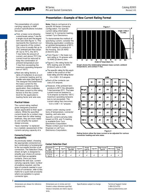
Presentation—Example of New Current Rating Format<br />
Note: Data is not typical of a<br />
specific M <strong>Series</strong> connector<br />
configuration. For specific<br />
current rating information<br />
based on % connector loading,<br />
contact Tyco Electronics.<br />
To demonstrate the method of<br />
specifying current, consider the<br />
following application conditions;<br />
an ambient temperature of 65°C,<br />
a 50% loading of contacts in<br />
the housing, <strong>and</strong> 20 AWG<br />
[0.6mm 2] wire.<br />
■ From Figure 1, the base current<br />
rating is 14 ampere with<br />
18 AWG [0.8mm 2] wire.<br />
■ Figure 2, the rating factor for<br />
50% loading <strong>and</strong> 20 AWG<br />
[0.6mm 2] wire is 0.68.<br />
■ The specific rating for this applic<br />
a t i o nis the product of the<br />
base rating <strong>and</strong> the rating factor:<br />
14 x 0.68 = 9.5 ampere<br />
■ Each of the contacts can<br />
carry 9.5 ampere.<br />
■ However, if the ambient temperature<br />
is 80°C the allowable<br />
T-rise becomes 25°C. The base<br />
current must be lowered to<br />
12.8 ampere so that the 105°C<br />
maximum operating temperature<br />
is not exceeded. The<br />
current rating then becomes:<br />
12.8 x 0.68 = 8.7 a m p e r e .<br />
contact under varying conditions<br />
of temperature, connector<br />
loading, <strong>and</strong> wire size.<br />
Specific current-carrying data<br />
based on EOL <strong>and</strong> % loading<br />
is available from Tyco<br />
Electronics Corporation.<br />
Please contact your local Sales<br />
Engineer or call Tyco<br />
Electronics Corporation.<br />
Contact Selection Chart<br />
Dimensions are in inches <strong>and</strong> millimeters<br />
unless otherwise specified.<br />
Values in brackets are metric equivalents.<br />
Figure 1<br />
Graph shows the relationship between base current, ambient<br />
temperature, <strong>and</strong> contact T-rise.<br />
Figure 2<br />
Rating factors allow the base current to be adjusted for various<br />
connector loading <strong>and</strong> wire sizes.<br />
Connector<br />
Type<br />
Type I Type II<br />
High Current<br />
Type II/III+<br />
Type III+<br />
Posted<br />
Type III+<br />
Type XII<br />
High Current<br />
Type XII<br />
Mini-Coax<br />
Sub-Mini<br />
Coax<br />
M <strong>Series</strong> ✔ ✔ ✔ ✔ ✔<br />
M <strong>Series</strong><br />
Special<br />
✔ ✔ ✔ ✔ ✔ ✔ ✔ ✔ ✔<br />
Specifications subject to change. Technical Support Center<br />
1-800-522-6752<br />
www.tycoelectronics.com<br />
Catalog 82003<br />
Revised 3-01