
Create successful ePaper yourself
Turn your PDF publications into a flip-book with our unique Google optimized e-Paper software.
<strong>gambit</strong> <strong>series</strong> <strong>ADC2</strong><br />
24 Bit / 192 kHz A/D Converter<br />
BNC<br />
sync source<br />
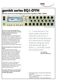
<strong>gambit</strong> <strong>series</strong><br />
AES 48.0kHz sf x4<br />
44.1kHz sf x 2<br />
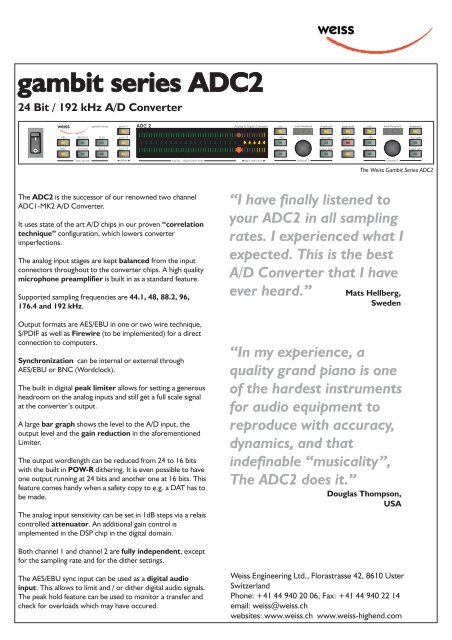
The <strong>ADC2</strong> is the successor of our renowned two channel<br />
ADC1-MK2 A/D Converter.<br />
It uses state of the art A/D chips in our proven “correlation<br />
technique” configuration, which lowers converter<br />
imperfections.<br />
The analog input stages are kept balanced from the input<br />
connectors throughout to the converter chips. A high quality<br />
microphone preamplifier is built in as a standard feature.<br />
Supported sampling frequencies are 44.1, 48, 88.2, 96,<br />
176.4 and 192 kHz.<br />
Output formats are AES/EBU in one or two wire technique,<br />
S/PDIF as well as Firewire (to be implemented) for a direct<br />
connection to computers.<br />
Synchronization can be internal or external through<br />
AES/EBU or BNC (Wordclock).<br />
The built in digital peak limiter allows for setting a generous<br />
headroom on the analog inputs and still get a full scale signal<br />
at the converter’s output.<br />
A large bar graph shows the level to the A/D input, the<br />
output level and the gain reduction in the aforementioned<br />
Limiter.<br />
The output wordlength can be reduced from 24 to 16 bits<br />
with the built in POW-R dithering. It is even possible to have<br />
one output running at 24 bits and another one at 16 bits. This<br />
feature comes handy when a safety copy to e.g. a DAT has to<br />
be made.<br />
The analog input sensitivity can be set in 1dB steps via a relais<br />
controlled attenuator.<br />
An additional gain control is<br />
implemented in the DSP chip in the digital domain.<br />
Both channel 1 and channel 2 are fully independent,<br />
except<br />
for the sampling rate and for the dither settings.<br />
The AES/EBU sync input can be used as a digital audio<br />
input.<br />
This allows to limit and / or dither digital audio signals.<br />
The peak hold feature can be used to monitor a transfer and<br />
check for overloads which may have occured.<br />
pow-r 1<br />
1<br />
pow-r 2 +48V<br />
input gain digital in<br />
pow-r 3<br />
dither<br />
ADC 2<br />
65 60 55 50 45 40 35 30 25 20 18 16 14 12 10<br />
2<br />
analog / digital peak level<br />
8<br />
6<br />
4<br />
2<br />
Analog to Digital Converter<br />
0<br />
8 6 4 2 0<br />
gain reduction<br />
mic level/threshold<br />
low-cut<br />
channel 1<br />
threshold<br />
output gain<br />
peak hold<br />
ganged<br />
mic level/threshold<br />
The <strong>Weiss</strong> Gambit Series <strong>ADC2</strong><br />
<strong>Weiss</strong> Engineering Ltd., Florastrasse 42, 8610 Uster<br />
Switzerland<br />
Phone: +41 44 940 20 06, Fax: +41 44 940 22 14<br />
email: weiss@weiss.ch<br />
websites: www.weiss.ch www.weiss-highend.com<br />
+48V<br />
low-cut<br />
channel 2<br />
“I have finally listened to<br />
your <strong>ADC2</strong> in all sampling<br />
rates. I experienced what I<br />
expected. This is the best<br />
A/D Converter that I have<br />
ever heard.” Mats Hellberg,<br />
Sweden<br />
“In my experience, a<br />
quality grand piano is one<br />
of the hardest instruments<br />
for audio equipment to<br />
reproduce with accuracy,<br />
dynamics, and that<br />
indefinable “musicality”,<br />
The <strong>ADC2</strong> does it.”<br />
Douglas Thompson,<br />
USA<br />
threshold<br />
input gain<br />
output gain
<strong>ADC2</strong>, 24Bit / 192kHz A/D Converter<br />
Inputs:<br />
� Balanced LINE and MIC inputs on separate<br />
connectors.<br />
� MIC input with switchable phantom power.<br />
� Input sensitivity is settable in each channel<br />
independently (or ganged) with two rotary<br />
encoders.<br />
� Line Input sensitivity: -16dBu to +26 dBu for<br />
0dBFS output.<br />
� Mic Input sensitivity: -54dBu to +6dBu for<br />
0dBFS output.<br />
� Separate AES/EBU input on XLR for<br />
synchronization and/or audio input to the DSP,<br />
which allows for use of the <strong>ADC2</strong> for<br />
redithering and limiting of digital Signals.<br />
Outputs:<br />
� AES/EBU on XLR in one or two wire<br />
technique, S/PDIF on RCA, Firewire.<br />
Synchronization:<br />
� Internal sync selectable 44.1kHz, 48kHz,<br />
88.2kHz, 96kHz, 176.4kHz, 192kHz.<br />
� External sync from Wordsync Input (BNC) or<br />
from AES/EBU input.<br />
� Wordsync output on a BNC connector.<br />
Metering:<br />
� One bargraph per channel with peak hold.<br />
� Two over LEDs<br />
� Two numerical displays for input sensitivity<br />
Miscellaneous:<br />
� 19 inch rack mount frame, 1HU.<br />
� Mains voltage 115 / 230 VAC, 50/60 Hz.<br />
Block Diagram:<br />
Wordclock<br />
Input<br />
AES/EBU<br />
Input<br />
Line Input<br />
Amplifier<br />
Microphone<br />
Preamp<br />
Synchronization<br />
Generator<br />
DSP Features:<br />
� POW-R dithering to 16 bits, settable to three<br />
different algorithms according to the POW-R<br />
standard.<br />
� SNR enhancement.<br />
� Level bar graph meter.<br />
� Digital peak limiter<br />
Frontpanel Elements:<br />
�<br />
�<br />
�<br />
�<br />
�<br />
�<br />
Attenuator A/D<br />
Converter<br />
Mains Switch.<br />
2 rotary encoders for Level control.<br />
Several keys for various parameters with direct<br />
access. No menu structures used.<br />
Two bar graphs 0..-65dB.<br />
Two bar graphs for gain reduction.<br />
Two "over" LEDs.<br />
Backpanel Elements:<br />
� One BNC connector for sampling clock input with<br />
termination switch (on/off).<br />
� One XLR connector for sampling clock input<br />
(AES/EBU) and at the same time for the digital<br />
input to the DSP. With termination switch (on/off).<br />
� Four XLR connectors for analog inputs (2 LINE, 2<br />
MIC).<br />
� Two XLR connectors for AES output.<br />
� One RCA connector for S/PDIF output.<br />
� One Firewire connector.<br />
� One switch for dither setting for main outputs.<br />
� One switch for 1wire / 2 wire AES out mode<br />
setting.<br />
Digital Signal<br />
Processor<br />
AES/EBU<br />
Output<br />
S/PDIF<br />
Output<br />
Firewire<br />
Output<br />
Metering