Niveaurelais NS 20 - Ziehl industrie-elektronik GmbH + Co KG
Niveaurelais NS 20 - Ziehl industrie-elektronik GmbH + Co KG
Niveaurelais NS 20 - Ziehl industrie-elektronik GmbH + Co KG

Create successful ePaper yourself
Turn your PDF publications into a flip-book with our unique Google optimized e-Paper software.
MINIPAN ® digital panel meters, temperature- and mains controlling,<br />
special purpose instruments for customer requirements www.ziehl.com<br />
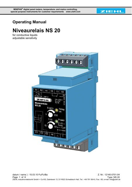
Operating Manual<br />
<strong>Niveaurelais</strong> <strong>NS</strong> <strong>20</strong><br />
for conductive liquids<br />
adjustable sensitivity<br />
datum / name ) : 15.03.10 Fu/Fz/Ba Z. Nr.: 12140-0701-04<br />
Page 1 of 8 Type: <strong>NS</strong> <strong>20</strong><br />
ZIEHL <strong>industrie</strong>-<strong>elektronik</strong> <strong>GmbH</strong> + <strong>Co</strong> <strong>KG</strong>, Daimlerstr.13, D-74523 Schwäbisch Hall, Tel.: +49 791 504-0, Fax: -56, e-mail: info@ziehl.de
Index Page<br />
Description.....................................................................................................................3<br />
Overview of functions.....................................................................................................3<br />
Action chart....................................................................................................................4<br />
<strong>Co</strong>nnection plan with 2 electrodes .................................................................................4<br />
<strong>Co</strong>nnection plan with 1 electrode...................................................................................5<br />
Display and operating elements.....................................................................................5<br />
Installation......................................................................................................................6<br />
Putting into operation.....................................................................................................6<br />
Adjusting the sensitivity .............................................................................................6<br />
Error search and measures ...........................................................................................6<br />
Technical data ...............................................................................................................7<br />
Housing..........................................................................................................................8<br />
datum / name ) : 15.03.10 Fu/Fz/Ba Z. Nr.: 12140-0701-04<br />
Page 2 of 8 Type: <strong>NS</strong> <strong>20</strong><br />
ZIEHL <strong>industrie</strong>-<strong>elektronik</strong> <strong>GmbH</strong> + <strong>Co</strong> <strong>KG</strong>, Daimlerstr.13, D-74523 Schwäbisch Hall, Tel.: +49 791 504-0, Fax: -56, e-mail: info@ziehl.de
Description<br />
Level-Relays <strong>NS</strong> <strong>20</strong> for conductive liquids can be used as monitors for 1 Level and for<br />
controlling a level between 2 electrodes.<br />
• 3 elektrodes for MIN/MAXcontrol<br />
• 2 elektrodes (E2 open) as level monitor<br />
• Sensitivity adjustable 5 kΩ…250 kΩ<br />
• LED for state of relay<br />
• Function of relay reversible (picks up or releases at top electrode)<br />
• Switching-delay adjustable 0,1…10 s<br />
• Housing 35 mm wide, mounting height 55 mm<br />
• Universal supply-voltage AC/DC 24-240 V<br />
Application level monitor:<br />
Protection from running dry or overflow, monitoring of pumps for leaks, detection of leaks.<br />
Application Min/Max:<br />
<strong>Co</strong>ntrolling a level between minimum (elektrode E2) and maximum (E3). As long as E3 is dry, a<br />
magnetic valve is opened (or a pump is running) and liquid is influenting. As soon as maximum<br />
(E3) is reached, the <strong>NS</strong> <strong>20</strong> closes the valve. When the level falls below E2, the cycle starts<br />
new.<br />
In reverse also discharging of a container can be controlled.<br />
Overview of functions example filling with 2 electrodes<br />
The detection of the level is made with a DC-free measuring of resistance between all<br />
electrodes The common electrode in E 1. A magnetic valve that is switched with relay-contacts<br />
15-18 opens and lets liquid in until the upper electrode E3 is in contact with the liquid. Then the<br />
relay releases (15-18 open) and the valve closes. The relay remains released as long as<br />
electrode E 2 is in contact with the liquid. When the level falls below E2, the relay picks up<br />
(LED Relay on, 15-18 close) and the procedure starts new with opening the valve. Thus the<br />
level of the liquid is kept between E 1 and E 2.<br />
For monitoring one level only or in applications to protect from running dry or overflow or leak<br />
detection, only electrodes E1 and E3 are connected.<br />
datum / name ) : 15.03.10 Fu/Fz/Ba Z. Nr.: 12140-0701-04<br />
Page 3 of 8 Type: <strong>NS</strong> <strong>20</strong><br />
ZIEHL <strong>industrie</strong>-<strong>elektronik</strong> <strong>GmbH</strong> + <strong>Co</strong> <strong>KG</strong>, Daimlerstr.13, D-74523 Schwäbisch Hall, Tel.: +49 791 504-0, Fax: -56, e-mail: info@ziehl.de
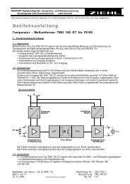
Action Chart<br />
Us<br />
Power<br />
LED<br />
E1-E3<br />
E1-E2<br />
Relais<br />
Relais<br />
1<br />
1<br />
15-18<br />
15-16<br />
15-18<br />
15-16<br />
ON<br />
OFF<br />
t1<br />
t1<br />
t1<br />
t1<br />
2 Electrodes 1 Electrode<br />
t1 = adjusted switching-delay<br />
LED Relay on = relay<br />
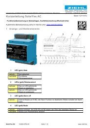
<strong>Co</strong>nnection Plan<br />
filling tank with 2 electrodes (E3 dipped, relay off 15 – 16 closed)<br />
1 electrodes 3 magnetic valve<br />
2 tank 4 basicelectrode<br />
datum / name ) : 15.03.10 Fu/Fz/Ba Z. Nr.: 12140-0701-04<br />
Page 4 of 8 Type: <strong>NS</strong> <strong>20</strong><br />
ZIEHL <strong>industrie</strong>-<strong>elektronik</strong> <strong>GmbH</strong> + <strong>Co</strong> <strong>KG</strong>, Daimlerstr.13, D-74523 Schwäbisch Hall, Tel.: +49 791 504-0, Fax: -56, e-mail: info@ziehl.de<br />
t1<br />
t1<br />
t1<br />
t1
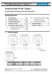
monitoring of liquid with 1 electrode (E3 dipped, relay on 15 – 18 closed)<br />
1 electrodes 3 magnetic valve<br />
2 tank 4 basicelectrode<br />
Display and Operating Elements<br />
1. LED Relay on<br />
2. Potentiometer for<br />
Sensitivity<br />
3. LED Power<br />
4. Potentiometer<br />
Switching-delay<br />
A1 A2 nc<br />
~ ~<br />
+ Us –<br />
AC/DC 24...240 V<br />
<strong>Niveaurelais</strong><br />
<strong>NS</strong> <strong>20</strong><br />
R (kΩ)<br />
E1 E2 E3<br />
16 15<br />
datum / name ) : 15.03.10 Fu/Fz/Ba Z. Nr.: 12140-0701-04<br />
Page 5 of 8 Type: <strong>NS</strong> <strong>20</strong><br />
ZIEHL <strong>industrie</strong>-<strong>elektronik</strong> <strong>GmbH</strong> + <strong>Co</strong> <strong>KG</strong>, Daimlerstr.13, D-74523 Schwäbisch Hall, Tel.: +49 791 504-0, Fax: -56, e-mail: info@ziehl.de<br />
5<br />
0,1<br />
.com<br />
t (s)<br />
nc<br />
250<br />
10<br />
18<br />
Ue = 250 V<br />
Ie = 2 A<br />
AC 15<br />
E1-E3 =<br />
Relay ...<br />
off<br />
on<br />
1<br />
12140-1<strong>20</strong>0-02<br />
Relay<br />
on<br />
Power<br />
1<br />
2<br />
3<br />
4
Installation<br />
• Installation in switchgear cabinet on 35 mm mounting rail or wall-mount with screws M4<br />
• <strong>Co</strong>nnection according to connection plan or type plate<br />
ATTENTION!<br />
Before switching on the unit make sure that the connected voltage corresponds with the<br />
voltage on the lateral type-plate!<br />
Observe the maximum temperature permissible when installing in switching<br />
cabinet. Make sure sufficient space to other equipment or heat sources. If the<br />
cooling becomes more difficult e.g. through close proximity of apparatus with<br />
elevated surface temperature or hindrance of the cooling air, the tolerable<br />
environmental temperature is diminishing.<br />
Putting into Operation<br />
ATTENTION<br />
Dangerous electrical voltage!<br />
May lead to electrical shock and burn.<br />
Before beginning of work switch unit and equipment free of voltage.<br />
LED Power on = ready<br />
LED Relay On on = relay picked up (15-16 open, 15-18 closed)<br />
Adjusting the sensitivity:<br />
• Start with potentiometer set for highest sensitivity/resistance (250 kΩ)<br />
• At malfunction because of too long cables (capacity of cable) or when conductive foam<br />
covers the electrodes reduce sensitivity (turn left).<br />
• At liquids with a high conductivity (e.g. dirty water) a low sensitivity can be set from the<br />
beginning<br />
Error Search<br />
• Relay doesn't switch<br />
- Check whether LED Power is on and if supply-voltage is connected properly to A1, A2 and i<br />
fit corresponds with the voltage on the lateral type-plate.<br />
- Check whether the electrodes are connected properly.<br />
• Relay switches though the electrodes are not in cintact with the liquid:<br />
- Check whether the electrodes ar bridged by a liquid film or by<br />
- Capacity of cable too high<br />
Normally both errors can be solved by setting the sensitivity to a lower resistance (turn<br />
potentiometer left)<br />
In case of any other malfunctions send it in for repair together with a description<br />
of the occurred malfunction.<br />
datum / name ) : 15.03.10 Fu/Fz/Ba Z. Nr.: 12140-0701-04<br />
Page 6 of 8 Type: <strong>NS</strong> <strong>20</strong><br />
ZIEHL <strong>industrie</strong>-<strong>elektronik</strong> <strong>GmbH</strong> + <strong>Co</strong> <strong>KG</strong>, Daimlerstr.13, D-74523 Schwäbisch Hall, Tel.: +49 791 504-0, Fax: -56, e-mail: info@ziehl.de
Technical Data<br />
Supply voltage Us: AC/DC 24 – 240 V, 0 / 50 / 60 Hz < 3 W < 5 VA<br />
Tolerance DC <strong>20</strong>,4 - 297 V, AC <strong>20</strong> - 264 V<br />
Level-electrodes (E1 , E2 , E3)<br />
max. voltage: < 6 Veff<br />
max. current:
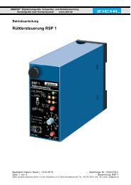
Housing design V2<br />
Mounting height 55 mm<br />
Dimensions (B x H x T) 35 x 90 x 58 mm<br />
Line connection 1 wire each 1 x 4 mm 2<br />
Stranded wire with wire-end sleeves each 1 x 2,5 mm 2<br />
Protection housing IP 30<br />
Protection terminals IP <strong>20</strong><br />
Attachment Snap-mount on DIN-rail 35 mm according to<br />
EN 60 715 or screws M4<br />
Weight app. 130 g<br />
Sunject to technical changes<br />
Housing V2 Dimensions in mm<br />
61,8<br />
45<br />
58<br />
48<br />
16,5<br />
3<br />
(90)<br />
Option<br />
1 2 3<br />
1 Oberteil / cover<br />
2 Unterteil / base<br />
3 Riegel / bar for snap mounting<br />
4 Plombenlasche / latch for sealing<br />
5 Frontplatteneinsatz / front panel<br />
6 Kennzeichen für unten / position downward<br />
7 Riegel bei Wandbefestigung mit Schrauben. Riegelbohrung Ø 4,2 mm / for fixing to wall<br />
with screws, Ø 4,2 mm<br />
datum / name ) : 15.03.10 Fu/Fz/Ba Z. Nr.: 12140-0701-04<br />
Page 8 of 8 Type: <strong>NS</strong> <strong>20</strong><br />
ZIEHL <strong>industrie</strong>-<strong>elektronik</strong> <strong>GmbH</strong> + <strong>Co</strong> <strong>KG</strong>, Daimlerstr.13, D-74523 Schwäbisch Hall, Tel.: +49 791 504-0, Fax: -56, e-mail: info@ziehl.de<br />
4<br />
6<br />
5<br />
7<br />
35<br />
98<br />
116