Operating manual Speed Controller NU 125 D - ziehl.de
Operating manual Speed Controller NU 125 D - ziehl.de
Operating manual Speed Controller NU 125 D - ziehl.de

You also want an ePaper? Increase the reach of your titles
YUMPU automatically turns print PDFs into web optimized ePapers that Google loves.
MINIPAN ® digital panel meters, temperature- and mains controlling,<br />
special purpose instruments for customer requirements www.<strong>ziehl</strong>.<strong>de</strong><br />
ZIEHL industrie-elektronik GmbH+Co, Daimlerstr.13, D-74523 Schwäbisch Hall, Tel.: +49 791 504-0, Fax: -56, e-mail: info@<strong>ziehl</strong>.<strong>de</strong><br />
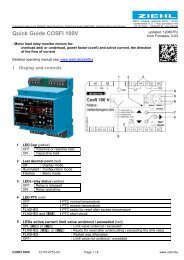
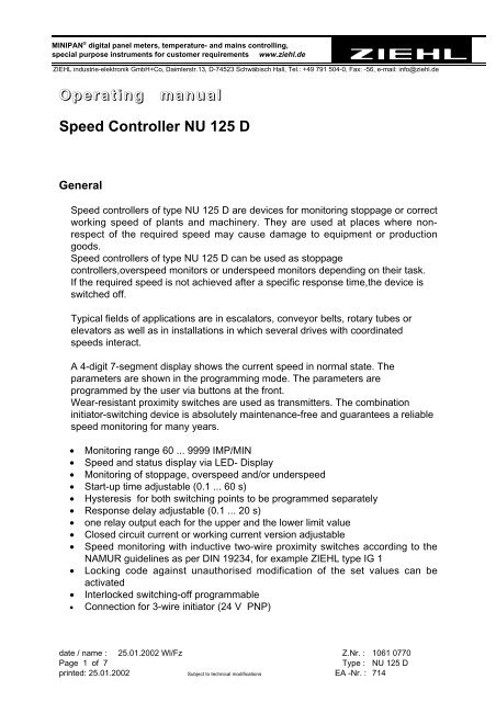
<strong>Operating</strong> <strong>manual</strong><br />
<strong>Speed</strong> <strong>Controller</strong> <strong>NU</strong> <strong>125</strong> D<br />
General<br />
<strong>Speed</strong> controllers of type <strong>NU</strong> <strong>125</strong> D are <strong>de</strong>vices for monitoring stoppage or correct<br />
working speed of plants and machinery. They are used at places where nonrespect<br />
of the required speed may cause damage to equipment or production<br />
goods.<br />
<strong>Speed</strong> controllers of type <strong>NU</strong> <strong>125</strong> D can be used as stoppage<br />
controllers,overspeed monitors or un<strong>de</strong>rspeed monitors <strong>de</strong>pending on their task.<br />
If the required speed is not achieved after a specific response time,the <strong>de</strong>vice is<br />
switched off.<br />
Typical fields of applications are in escalators, conveyor belts, rotary tubes or<br />
elevators as well as in installations in which several drives with coordinated<br />
speeds interact.<br />
A 4-digit 7-segment display shows the current speed in normal state. The<br />
parameters are shown in the programming mo<strong>de</strong>. The parameters are<br />
programmed by the user via buttons at the front.<br />
Wear-resistant proximity switches are used as transmitters. The combination<br />
initiator-switching <strong>de</strong>vice is absolutely maintenance-free and guarantees a reliable<br />
speed monitoring for many years.<br />
• Monitoring range 60 ... 9999 IMP/MIN<br />
• <strong>Speed</strong> and status display via LED- Display<br />
• Monitoring of stoppage, overspeed and/or un<strong>de</strong>rspeed<br />
• Start-up time adjustable (0.1 ... 60 s)<br />
• Hysteresis for both switching points to be programmed separately<br />
• Response <strong>de</strong>lay adjustable (0.1 ... 20 s)<br />
• one relay output each for the upper and the lower limit value<br />
• Closed circuit current or working current version adjustable<br />
• <strong>Speed</strong> monitoring with inductive two-wire proximity switches according to the<br />
NAMUR gui<strong>de</strong>lines as per DIN 19234, for example ZIEHL type IG 1<br />
• Locking co<strong>de</strong> against unauthorised modification of the set values can be<br />
activated<br />
• Interlocked switching-off programmable<br />
• Connection for 3-wire initiator (24 V PNP)<br />
date / name : 25.01.2002 Wl/Fz Z.Nr. : 1061 0770<br />
Page 1 of 7 Type : <strong>NU</strong> <strong>125</strong> D<br />
printed: 25.01.2002 Subject to technical modifications EA -Nr. : 714
Function<br />
If the speed controller is switched on at the same time as the drive to be<br />
monitored, monitoring is only active after expiry of the programmed start-up<br />
bridging time.<br />
If supply voltage is constantly fed, monitoring can be started via the contact Y1-Y2<br />
(terminals 2/3). Upon opening of this contact, the programmed start-up time starts<br />
running. During start-up-time "StA" blinks in the display alternating with the actual<br />
measured value.<br />
At un<strong>de</strong>r-speed, K1 switches off. "L" blinks alternating with the actual measured<br />
value.<br />
At over-speed, K2 switches off. "H" blinks alternating with the actual measured<br />
value.<br />
If the speed exceeds maximum (9999), "H" and "EEEE" blink alternating. If the<br />
speed exceeds maximum (9999) and alarm for over-speed is <strong>de</strong>-activated, during<br />
start-up time or response <strong>de</strong>lay or with closed contact "Start", the display shows<br />
"EEEE".<br />
If interlocked switching is activated, the alarm remains active when the signal<br />
returns into the permissible range. "LocL" (Alarm 1, relay K1) respectively "LocH"<br />
(alarm 2, K2) blink alternating with the measured value. For Reset push button<br />
"Set" >0,5 s.<br />
If the co<strong>de</strong> lock is activated, the settings can only be changed after entering the<br />
co<strong>de</strong>. Attempts to change settings result in display "co<strong>de</strong>" (short) followed by<br />
"5000". Now the co<strong>de</strong> can be entered wit up/down. Pust "Set" to return to normal<br />
display mo<strong>de</strong>.<br />
Installation - Putting into operation<br />
The plug base can be mounted either with<br />
• 35 mm mounting rail according to DIN 50 002 or<br />
• M4 screws<br />
• Wiring directly to plug base<br />
• Connect wires as per wiring scheme<br />
• Plug in electronics and fix with knurled screw<br />
ATTENTION<br />
Before switching on voltage make sure, that the operational voltage Us of the lateral<br />
type plate and the mains voltage connected to the relay are the same.<br />
date / name : 25.01.2002 Wl/Fz Z.Nr. : 1061 0770<br />
Page 2 of 7 Type : <strong>NU</strong> <strong>125</strong> D<br />
printed: 25.01.2002 Subject to technical modifications EA -Nr. : 714
Factory-preset:<br />
• Lower limit: 500 Imp./min., hysteresis: 10 Imp./min., no interlocked switching,<br />
relay on, when signal above limit<br />
• Upper limit: 5000 Imp./min., hysteresis: 100 Imp./min., no interlocked switching,<br />
relay on, when signal below limit<br />
• Start-up-time: 2 s<br />
• Response <strong>de</strong>lay: 0,5 s<br />
• Display rate: 0,5 s<br />
• Co<strong>de</strong> off<br />
Return to factory-settings by pushing "Set" while in display-mo<strong>de</strong> for 5 s.<br />
Setting the limits<br />
If no button is pushed for 30 s while programming, the relay returns into display<br />
mo<strong>de</strong>. The last set value is being stored.<br />
In program mo<strong>de</strong> a LED in the lower right corner of the display lights up.<br />
Upper Limit:<br />
• press up/down until display "H"<br />
• press Set and the actual limit value is displayed, e.g. "5000"<br />
• change value in between 60...9000 IMP/min. When setting "0", monitoring for<br />
over-speed is switched off<br />
• "Set" stores the value and display returns to "H"<br />
• push up/down to reach other settings<br />
Hysteresis of upper limit:<br />
• press up/down until display "HH"<br />
• press Set and the actual value is displayed, e.g. "100"<br />
• change value in between 1...9999 IMP/min.<br />
• "Set" stores the value and display returns to "HH"<br />
• press up/down to reach other settings<br />
Lower Limit:<br />
• press up/down until display "L"<br />
• press Set and the actual limit value is displayed, e.g. "500"<br />
• change value in between 60...9000 IMP/min. When setting "0", monitoring for<br />
un<strong>de</strong>r-speed is switched off<br />
• "Set" stores the value and display returns to "L"<br />
• push up/down to reach other settings<br />
date / name : 25.01.2002 Wl/Fz Z.Nr. : 1061 0770<br />
Page 3 of 7 Type : <strong>NU</strong> <strong>125</strong> D<br />
printed: 25.01.2002 Subject to technical modifications EA -Nr. : 714
Hysteresis of lower limit:<br />
• press up/down until display "HL"<br />
• press Set and the actual value is displayed, e.g. "10"<br />
• change value in between 1...9999 IMP/min.<br />
• "Set" stores the value and display returns to "HL"<br />
• press up/down to reach other settings<br />
Start-up time<br />
• press up/down until display "StA"<br />
• press Set and the actual value is displayed, e.g. "2.0"<br />
• change value in between 0.1 ... 60.0 s.<br />
• "Set" stores the value and display returns to "StA"<br />
• push up/down to reach other settings<br />
Response-time (Delay):<br />
• press up/down until display "dEL"<br />
• press Set and the actual value is displayed, e.g. "0.5"<br />
• change value in between 0.1 ... 20.0 s.<br />
• "Set" stores the value and display returns to "dEL"<br />
• push up/down to reach other settings<br />
Display rate:<br />
• press up/down until display "rAtE"<br />
• press Set and the actual value is displayed, e.g. "0.5"<br />
• change value (0,1 s; 0,5 s; 1 s).<br />
• "Set" stores the value and display returns to "rAtE"<br />
• push up/down to reach other settings<br />
Interlocked switching off<br />
When activated the relays switch back after an alarm only after a Reset.<br />
• press up/down until display "Loc"<br />
• press Set and the actual setting is displayed, e.g. "H0L0"<br />
• change with up/down as follows:<br />
• "H0L0" upper limit not intlocked / lower limit not interlocked<br />
• "H0L1" upper limit not intlocked / lower limit interlocked<br />
• "H1L0" upper limit intlocked / lower limit not interlocked<br />
• "H0L0" upper limit intlocked / lower limit interlocked<br />
• "Set" stores the setting and display returns to "Loc"<br />
• push up/down to reach other settings<br />
In operation a reset is possible by pressing "Set" for 0,5 s or switching off and on<br />
of the supply voltage.<br />
date / name : 25.01.2002 Wl/Fz Z.Nr. : 1061 0770<br />
Page 4 of 7 Type : <strong>NU</strong> <strong>125</strong> D<br />
printed: 25.01.2002 Subject to technical modifications EA -Nr. : 714
Relay function (closed circuit / operating current mo<strong>de</strong>)<br />
The relays can be operated in closed circuit mo<strong>de</strong> (picked up when signal is<br />
between the limits) or operating current mo<strong>de</strong> (picks up when limit is excee<strong>de</strong>d).<br />
• press up/down until display "rEL"<br />
• press Set and the actual setting is displayed, e.g. "1r2r"<br />
• change with up/down as follows:<br />
• "1r2r" K1 in closed circuit mo<strong>de</strong> / K2 in closed circuit mo<strong>de</strong><br />
• "1r2Ar" K1 in closed circuit mo<strong>de</strong> / K2 in operating current mo<strong>de</strong><br />
• "1A2r" K1 in operating current mo<strong>de</strong> / K2 in closed circuit mo<strong>de</strong><br />
• "1A2A" K1 in operating current mo<strong>de</strong> / K2 in operating current mo<strong>de</strong><br />
• "Set" stores the setting and display returns to "Loc"<br />
• push up/down to reach other settings<br />
Co<strong>de</strong> on/off<br />
The <strong>NU</strong> <strong>125</strong> D can be locked by activating a preset co<strong>de</strong>. With active lock, settings<br />
can be ma<strong>de</strong> 2 minutes after entering the correct co<strong>de</strong>. The co<strong>de</strong> is "5040" (5040<br />
cannot be changed) and can be activated as follows:<br />
• press up/down until display "codE"<br />
• press Set and "5000" is displayed<br />
• change with up/down to "5040"<br />
• "Set" shows the actual setting, e.g. "0"<br />
• change with up/down ("0" = off, "1" = on)<br />
• "Set" stores the setting and display changes to "Co<strong>de</strong>"<br />
• push up/down to reach other settings<br />
The lock will be active 2 min. after activating the co<strong>de</strong>. When switching off and on<br />
the supply voltage, the lock will be active immediatels.<br />
date / name : 25.01.2002 Wl/Fz Z.Nr. : 1061 0770<br />
Page 5 of 7 Type : <strong>NU</strong> <strong>125</strong> D<br />
printed: 25.01.2002 Subject to technical modifications EA -Nr. : 714
Technical Data<br />
Supply voltage Us AC 220 - 240 V DC 24 - 60 V<br />
Tolerance Supply voltage Us AC - 15 ... + 10 % DC 19 … 81 V<br />
Other voltages upon request<br />
Frequency 50 - 60 Hz<br />
Tolerance frequency 48 ... 62 Hz<br />
Power consumption < 5 VA<br />
<strong>Speed</strong> monitoring inductive two-wire proximity switch according<br />
to to the NAMUR gui<strong>de</strong>lines as per DIN<br />
19234<br />
Averaging of 4 periods.<br />
Tolerance
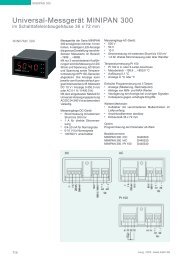
Wiring Scheme:<br />
Anlaufüberbrückung<br />
Öffner<br />
Hilfskontakt<br />
Housing Design S12:<br />
5<br />
,,<br />
,,<br />
,,<br />
,,<br />
,,<br />
,,<br />
,,<br />
,,<br />
+ -<br />
Initiator<br />
Namur<br />
Relais<br />
K1 K2<br />
12 14 11<br />
21<br />
1 2 3 4 5 6 7 8 9 10 11 12<br />
104,5<br />
116<br />
n<br />
Motor<br />
Drehzahl<br />
Erfassung<br />
24 22<br />
br bl ~<br />
36<br />
–<br />
A2<br />
~<br />
+<br />
A1<br />
date / name : 25.01.2002 Wl/Fz Z.Nr. : 1061 0770<br />
Page 7 of 7 Type : <strong>NU</strong> <strong>125</strong> D<br />
printed: 25.01.2002 Subject to technical modifications EA -Nr. : 714<br />
23,5<br />
82<br />
41,5<br />
80<br />
61<br />
38<br />
34<br />
1 Cable bushing<br />
41<br />
7,5<br />
17<br />
2 Mounting bore - hole<br />
3 Unlatching<br />
(only with rail - mounting)<br />
10<br />
U s<br />
17,5<br />
11,5<br />
2<br />
1<br />
14<br />
1<br />
1<br />
16<br />
5<br />
2<br />
5<br />
3<br />
41,5<br />
Base<br />
1 2 3 4 5 6 7 8 9 10 11 12<br />
6 Jackets for coding - pins<br />
82<br />
27,5