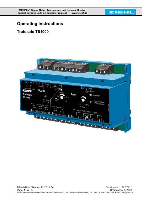
Operating instructions Trafosafe TS1000 - ziehl.de
Operating instructions Trafosafe TS1000 - ziehl.de
Operating instructions Trafosafe TS1000 - ziehl.de

You also want an ePaper? Increase the reach of your titles
YUMPU automatically turns print PDFs into web optimized ePapers that Google loves.
MINIPAN ® Digital Meter, Temperature and Network Monitor<br />
Special purpose units on customer request www.<strong>ziehl</strong>.<strong>de</strong><br />
<strong>Operating</strong> <strong>instructions</strong><br />
<strong>Trafosafe</strong> <strong>TS1000</strong><br />
Edited (Date / Name): 11/17/11 Sc Drawing no. 1192 0711.1<br />
Page 1 of 12 Designation: <strong>TS1000</strong><br />
ZIEHL industrie-elektronik GmbH + Co KG, Daimlerstr.13, D-74523 Schwäbisch Hall, Tel.: +49 791 504-0, Fax: -56, e-mail: info@<strong>ziehl</strong>.<strong>de</strong>
Table of contents<br />
1. Application and brief <strong>de</strong>scription .......................................................................... 3<br />
2. Overview of the functions ...................................................................................... 3<br />
3. Wiring diagram ........................................................................................................ 4<br />
4. Display and controls ............................................................................................... 4<br />
5. Detailed <strong>de</strong>scription ................................................................................................ 5<br />
5.1 Fan mo<strong>de</strong> ...................................................................................................... 5<br />
5.2 FAN run-on times ......................................................................................... 6<br />
5.3 FAN current monitor .................................................................................... 6<br />
5.4 PTC FAN ....................................................................................................... 6<br />
5.5 Functions Alarm 1 ....................................................................................... 6<br />
5.6 Functions Alarm 2 ....................................................................................... 7<br />
5.7 Functions Fan test ....................................................................................... 7<br />
5.8 Functions Error Reset/Calibrate button ..................................................... 7<br />
5.9 Functions Reset/Test (PTC-TRANS) button .............................................. 7<br />
5.10 Functions of the display elements ............................................................. 8<br />
6. Important Information ............................................................................................. 9<br />
7. Installation ............................................................................................................... 9<br />
8. Commissioning ..................................................................................................... 10<br />
9. Technical Data ....................................................................................................... 10<br />
10. Mounting type V8 .................................................................................................. 12<br />
Page<br />
Edited (Date / Name): 11/17/11 Sc Drawing no. 1192 0711.1<br />
Page 2 of 12 Designation: <strong>TS1000</strong><br />
ZIEHL industrie-elektronik GmbH + Co KG, Daimlerstr.13, D-74523 Schwäbisch Hall, Tel.: +49 791 504-0, Fax: -56, e-mail: info@<strong>ziehl</strong>.<strong>de</strong>
1. Application and brief <strong>de</strong>scription<br />
The <strong>Trafosafe</strong> <strong>TS1000</strong> is used on dry transformers with forced cooling.<br />
It monitors the temperature of the transformer, controls the fans for cooling, sends an<br />
alarm when an advance warning temperature has been excee<strong>de</strong>d and switches the<br />
transformer off if the temperature continues to increase.<br />
Up to 6 fans can be individually controlled by the <strong>TS1000</strong>; contactors and motor<br />
protection switches are omitted.<br />
When monitoring the transformer with a Pt 100 temperature sensor, the <strong>TS1000</strong> can be<br />
used as a pure fan controller.<br />
2. Overview of the functions<br />
Universal control voltage AC/DC 24-240 V<br />
Temperature monitoring:<br />
1 PTC thermistor for the fan control (1T1/1T2) = triggering with an external contact<br />
when using as a fan control<br />
1 each PTC thermistor advance warning (2T1/2T2) and shutdown (3T1/3T2) with<br />
monitoring of short-circuits and interruptions<br />
Caution: When using as a fan controller, the inputs must each be wired with one each<br />
1kOhm resistor.<br />
1 relay for advance warning (K2) in closed-circuit current version = function<br />
monitoring<br />
1 relay for shutdown (K3) in open-circuit version = no on-pulse contact<br />
Test/Reset button for function test<br />
Air controller and monitor:<br />
Direct connection for up to 6 fans<br />
Automatic extension of the fan mo<strong>de</strong> during higher loads<br />
Monitoring for errors (over/un<strong>de</strong>r current)<br />
Self-calibration of the current monitoring to the fans<br />
Adjustable current threshold for fan control (±5% … ±40%)<br />
Automatic fan test every 1-30 days, disconnectible<br />
Current relay for fan errors<br />
Clear displays with LEDs<br />
Edited (Date / Name): 11/17/11 Sc Drawing no. 1192 0711.1<br />
Page 3 of 12 Designation: <strong>TS1000</strong><br />
ZIEHL industrie-elektronik GmbH + Co KG, Daimlerstr.13, D-74523 Schwäbisch Hall, Tel.: +49 791 504-0, Fax: -56, e-mail: info@<strong>ziehl</strong>.<strong>de</strong>
3. Wiring diagram<br />
13 A max.<br />
4. Display and controls<br />
13 A max.<br />
1. LED network 7. LED calibration<br />
2. Reset/Test button 8. Error Reset / Calibrate button<br />
3. LED fan test 9. Fan LEDs<br />
4. Pot fan test 10. LED fan run-on<br />
5. Pot I-error 11. Sensor LEDs<br />
6. Alarm LED<br />
Edited (Date / Name): 11/17/11 Sc Drawing no. 1192 0711.1<br />
Page 4 of 12 Designation: <strong>TS1000</strong><br />
ZIEHL industrie-elektronik GmbH + Co KG, Daimlerstr.13, D-74523 Schwäbisch Hall, Tel.: +49 791 504-0, Fax: -56, e-mail: info@<strong>ziehl</strong>.<strong>de</strong>
5. Detailed <strong>de</strong>scription<br />
3 PTC thermistors (PTC-TRANS), per 1…6 PTC thermistors in series can be<br />
connected (max. summing initial resistance 1500 Ω) for the functions fan (FAN),<br />
advance warning (Alarm1) and shutdown (Alarm2)<br />
Fan function (FAN): When the rated trigger temperature (NAT) of the thermistor<br />
(PTC) is excee<strong>de</strong>d on 1T1/1T2, the FAN relays switch on consecutively pair by pair<br />
with 10s intervals (FAN 1+4, FAN 2+5 and FAN 3+6). Red LED 1T1/1T2 illuminated.<br />
Function Alarm 1 (advance warning and function monitoring): 1 dry contact<br />
(reversing switch). Relay K2 drops if thermistor on 2T1/2T2 NAT exceeds. (Closedcircuit<br />
current version, short wiper signal when switching on the control voltage). Red<br />
LED 2T1/2T2 illuminated when NAT was excee<strong>de</strong>d and flashes on sensor error.<br />
Function Alarm 2 (shutdown): 1 dry contact (reversing switch). Relay K3 energizes if<br />
thermistor on 2T1/2T2 NAT exceeds. Red LED 3T1/3T2 illuminated when NAT was<br />
excee<strong>de</strong>d and flashes on sensor error.<br />
Sensor interruption and short-circuit monitoring of the PTC for Alarm1 (2T1/2T2) and<br />
Alarm2 (3T1/3T2), with message to Alarm1 (to test the <strong>de</strong>vice for 10 minutes<br />
disconnectible, press Reset/Test button for 15 s)<br />
Saves triggering of Alarm1 and Alarm2 (Alarm LEDs flash, relays switch back)<br />
Fan run-on 20 min., automatic extension during frequent fan use<br />
Test / Reset button for testing the relay outputs, fan run-on abort and LED messages<br />
reset<br />
Alarm state display through LED<br />
Temperature monitoring of the fan motors (PTC-FAN) with 2 PTC thermistors,<br />
connectible per 1…9 thermistor in series (max. summing initial resistance 1500 Ω).<br />
Self-monitoring routine when switching on (power up test LED for 2s)<br />
Error Reset / Calibrate button resetting FAN error messages and calibrating the fan<br />
motor current monitor.<br />
Rotary knob fan test for cyclically repeating fan test, adjustable "Manual mo<strong>de</strong> / 1…30<br />
days / off"<br />
I-Error rotary knob for setting the permissible ± <strong>de</strong>viation from the calibrated rated<br />
current<br />
5.1 Fan mo<strong>de</strong><br />
When using purely as a fan controller, the inputs 2T1/2T2 and 3T1/3T2 must each be<br />
wired with one each 1kOhm resistor.<br />
Shutdown value on 1T1/1T2 reached or start with external contact (break contact)<br />
Fans power up with 10 s interval pair-by-pair (1+4, 2+5, 3+6), each FAN-LEDs<br />
illuminated green, FAN LEDs not yet switched in flash green<br />
Non-used FAN outputs do not switch in<br />
Red LED 1T1/1T2 illuminated<br />
Reclosing value reached on 1T1/1T2<br />
LED "Timer <strong>de</strong>lay" illuminated<br />
FAN run-on time running<br />
Switch off of the fan after expiration of the run-on time<br />
Red LED 1T1/1T2 off<br />
Edited (Date / Name): 11/17/11 Sc Drawing no. 1192 0711.1<br />
Page 5 of 12 Designation: <strong>TS1000</strong><br />
ZIEHL industrie-elektronik GmbH + Co KG, Daimlerstr.13, D-74523 Schwäbisch Hall, Tel.: +49 791 504-0, Fax: -56, e-mail: info@<strong>ziehl</strong>.<strong>de</strong>
5.2 FAN run-on times<br />
After switching on (first fan mo<strong>de</strong>), 20 minutes<br />
When fans switched on again within 60 minutes, the run-on time is exten<strong>de</strong>d to 40<br />
minutes<br />
When fans switched on again within 30 minutes, the run-on time is exten<strong>de</strong>d to 60<br />
minutes<br />
(Reset to 20 min. after 5 hours without fan mo<strong>de</strong> or if the control voltage fails).<br />
5.3 FAN current monitor<br />
During fan mo<strong>de</strong>, the fan currents are monitored (after a power up time of 10 s).<br />
The permissible <strong>de</strong>viation is set using the potentiometer "I Error" to ±5% to ±40%.<br />
Un<strong>de</strong>rcurrent <strong>de</strong>tection:<br />
FAN LED flashes red rapidly<br />
FAN remains switched on<br />
Relay K4 "FAN Error" attracts (41/44 closes) and reports error, LED "FAN Error"<br />
illuminates<br />
Overcurrent <strong>de</strong>tection:<br />
FAN LED shines red<br />
FAN is switched off<br />
Relay K4 "FAN Error" attracts (41/44 closes) and reports error, LED "FAN Error"<br />
illuminates<br />
The <strong>de</strong>tection of current errors (message K4) is saved zero-voltage maintained.<br />
Reset of error with the "Error Reset" button<br />
5.4 PTC FAN<br />
To operate without fan temperature monitoring, one bridge each between 4T1/4T2 and<br />
between 5T1/5T2 is required (inclu<strong>de</strong>d in scope of <strong>de</strong>livery)<br />
Shut-off value reached 4T1/4T2 (5T1/5T2)<br />
Fans 1…3 (4…6) will be switched off<br />
LED "PTC-FAN 1…3" (4…6) shines<br />
Relay K4 "FAN Error" attracts (41/44 closes) and reports error, LED "FAN Error"<br />
illuminates<br />
Reclosing value reached 4T1/4T2 (5T1/5T2)<br />
Fans 1…3 (4…6) start up consecutively with 10 s interval<br />
LED "PTC-FAN 1…3" (4…6) flashes<br />
"FAN Error" remains until reset through "Error Reset" button.<br />
5.5 Functions Alarm 1<br />
Shut-off value reached on 2T1/2T2 (PTC-TRANS Alarm1)<br />
Relay K2 "Alarm1" drops (21/22 closes) and reports error, LED "Alarm1" illuminates<br />
Red LED 2T1/2T2 illuminated<br />
Reclosing value reached on 2T1/2T2 (PTC-TRANS Alarm1)<br />
Relay K2 "Alarm1" attracts (21/24 closes), LED "Alarm1" flashes and indicates that<br />
temperature in the sensor circuit was excee<strong>de</strong>d.<br />
Red LED 2T1/2T2 off<br />
Sensor error on 2T1/2T2 (PTC-TRANS Alarm1)<br />
Relay K2 "Alarm1" drops (21/22 closes) and reports error, LED "Alarm1" flashes<br />
rapidly (is not saved)<br />
Red LED 2T1/2T2 flashes fast<br />
Edited (Date / Name): 11/17/11 Sc Drawing no. 1192 0711.1<br />
Page 6 of 12 Designation: <strong>TS1000</strong><br />
ZIEHL industrie-elektronik GmbH + Co KG, Daimlerstr.13, D-74523 Schwäbisch Hall, Tel.: +49 791 504-0, Fax: -56, e-mail: info@<strong>ziehl</strong>.<strong>de</strong>
5.6 Functions Alarm 2<br />
Shut-off value reached on 3T1/3T2 (PTC-TRANS Alarm2)<br />
Relay K3 "Alarm2" attracts (31/34 closes) and reports error, LED "Alarm2" illuminates<br />
Red LED 3T1/3T2 illuminated<br />
Reclosing value reached on 3T1/3T2 (PTC-TRANS Alarm2)<br />
Relay "Alarm2" drops (31/34 opens), LED "Alarm2" flashes and indicates that<br />
temperature in the sensor circuit was excee<strong>de</strong>d.<br />
Red LED 3T1/3T2 off<br />
Sensor error on 3T1/3T2 (PTC-TRANS Alarm2)<br />
Relay "Alarm1" drops (21/22 closes) and reports error, LED "Alarm1" illuminates, LED<br />
"Alarm2" flashes rapidly (is not saved)<br />
Red LED 3T1/3T2 flashes fast<br />
5.7 Functions Fan test<br />
Automatic fan test, can be set with the rotary fan test knob<br />
"Manual mo<strong>de</strong> – 1…30 days – off“<br />
Position 1…30 days:<br />
- Automatic periodical fan test according to preset time.<br />
The expired time is saved zero-voltage maintained (±1h)<br />
- LED "Fan test" illuminated<br />
- Fans run pair-by-pair consecutively for 60 s each (1+4, 2+5, 3+6)<br />
- Non-connected FAN outputs do not switch in<br />
- Monitoring of fans for un<strong>de</strong>r/ and overcurrent<br />
Off position:<br />
- Fan test switched off<br />
Manual mo<strong>de</strong> position:<br />
- LED "Fan test" flashes<br />
- Fans power up pair-by-pair with 10 s intervals (1+4, 2+5, 3+6)<br />
- Non-connected FAN outputs do not switch in<br />
- Monitoring of fans for un<strong>de</strong>r/ and overcurrent<br />
5.8 Functions Error Reset/Calibrate button<br />
Rests "FAN Error" (LED FAN Error on)<br />
Start calibration (pressed > 5s)<br />
5.9 Functions Reset/Test (PTC-TRANS) button<br />
Stops fan during run-on<br />
Resets PTC-TRANS FAN<br />
Resets Alarm1 and Alarm2 display<br />
Activate test function with Reset/Test button pressed > 2 s<br />
Aborts the test function when released<br />
- after 2 sec.: "ON" LED flashes<br />
- after 5 sec.: "ON" LED flashes, Alarm1 on (K2 off), LED Alarm1 on<br />
- after 8 sec.: "ON" LED flashes, Alarm2 on (K3 on), LED Alarm2 on<br />
- after 15 sec.: Setup mo<strong>de</strong>:<br />
Swtiched on for 10 min. (abort with reset)<br />
"ON" LED flashes quickly<br />
Alarm1 off (K2 on), LED Alarm1 off<br />
Alarm2 off (K3 off, LED Alarm2 off<br />
Sensor error <strong>de</strong>tection switched off<br />
No reset after PTC triggering required<br />
Edited (Date / Name): 11/17/11 Sc Drawing no. 1192 0711.1<br />
Page 7 of 12 Designation: <strong>TS1000</strong><br />
ZIEHL industrie-elektronik GmbH + Co KG, Daimlerstr.13, D-74523 Schwäbisch Hall, Tel.: +49 791 504-0, Fax: -56, e-mail: info@<strong>ziehl</strong>.<strong>de</strong>
5.10 Functions of the display elements<br />
Illuminated Flashes<br />
Flashes<br />
rapidly<br />
LED Red Green Green Red Green Red Display function See<br />
Calibration X Unit not calibrated 8. Commissioning<br />
X Calibration process started 8. Commissioning<br />
X Calibration completed /<br />
Valid calibration present<br />
8. Commissioning<br />
5.3 FAN current<br />
FANs X FAN overcurrent <strong>de</strong>tected monitoring<br />
X FAN switched on<br />
FAN power up (FAN still<br />
5.1 Fan mo<strong>de</strong><br />
X<br />
off)<br />
FAN current > 4A<br />
5.1 Fan mo<strong>de</strong><br />
X<br />
(during calibration) 8. Commissioning<br />
FAN un<strong>de</strong>rcurrent 5.3 FAN current<br />
X <strong>de</strong>tected<br />
monitoring<br />
FAN error<br />
PTC-TRAFO<br />
X FAN error 8. Commissioning<br />
5.3 FAN current<br />
monitoring<br />
5.4 FAN PTC<br />
- 1T1/1T2 X PTC > NAT<br />
- 2T1/2T2 X PTC > NAT 5.5 Function Alarm1<br />
X 2T sensor error 5.5 Function Alarm1<br />
- 3T1/3T2 X PTC > NAT 5.6 Function Alarm2<br />
X 3T sensor error 5.6 Function Alarm2<br />
PTC-FAN<br />
1…3<br />
X PTC-FAN > NAT 5.4 PTC-FAN<br />
4…6 X PTC-FAN saved triggering 5.4 PTC-FAN<br />
Alarm 2 X PTC on 3T > NAT<br />
NAT on sensor circuit 3T<br />
5.6 Function Alarm 2<br />
X<br />
was excee<strong>de</strong>d 5.6 Function Alarm 2<br />
X 3T sensor error 5.6 Function Alarm 2<br />
Alarm 1 X PTC on 2T > NAT 5.5 Function Alarm 1<br />
3T sensor error<br />
NAT on sensor circuit 2T<br />
5.6 Function Alarm 2<br />
X<br />
was excee<strong>de</strong>d 5.5 Function Alarm 1<br />
Network<br />
X 2T sensor error 5.5 Function Alarm 1<br />
LED X Unit switched on<br />
5.9 "PTC trans" test<br />
X Test mo<strong>de</strong> 1T, 2T and 3T function<br />
5.9 "PTC trans" test<br />
X Setup mo<strong>de</strong> 1T, 2T and 3T function<br />
LED<br />
Illuminated<br />
yellow<br />
Flashes<br />
yellow Display function See<br />
Fan test X Manual mo<strong>de</strong> fan test 5.7 Fan test<br />
X Automatic fan test<br />
Timer <strong>de</strong>lay X Fan run-on 5.1 Fan mo<strong>de</strong><br />
Edited (Date / Name): 11/17/11 Sc Drawing no. 1192 0711.1<br />
Page 8 of 12 Designation: <strong>TS1000</strong><br />
ZIEHL industrie-elektronik GmbH + Co KG, Daimlerstr.13, D-74523 Schwäbisch Hall, Tel.: +49 791 504-0, Fax: -56, e-mail: info@<strong>ziehl</strong>.<strong>de</strong>
6. Important Information<br />
To use the equipment flawless and safe, transport and store properly, install and start<br />
professionally and operate as directed.<br />
Only let persons work with the equipment who are familiar with installation, start and<br />
use and who have appropriate qualification corresponding to their function. They<br />
must observe the contents of the <strong>instructions</strong> manual, the information which are<br />
written on the equipment and the relevant security <strong>instructions</strong> for the setting up and<br />
the use of electrical units.<br />
The equipments are built according to DIN / EN and checked and leave the plant<br />
according to security in perfect condition. To keep this condition, observe the security<br />
<strong>instructions</strong> with the headline „Attention“ written in the <strong>instructions</strong> manual. Ignoring of<br />
the security <strong>instructions</strong> may lead to <strong>de</strong>ath, physical injury or damage of the<br />
equipment itself and of other apparatus and equipment.<br />
If, in any case the information in the <strong>instructions</strong> manual is not sufficient, please<br />
contact our company or the responsible representative.<br />
Instead of the industrial norms and regulations written in this <strong>instructions</strong> manual valid<br />
for Europe, you must observe out of their geographical scope the valid and relevant<br />
regulations of the corresponding country.<br />
7. Installation<br />
ATTENTION<br />
Dangerous electrical voltage!<br />
May lead to electrical shock and burn.<br />
Before beginning of work switch unit and equipment free of<br />
voltage.<br />
Observe the maximum temperature permissible when installing in switching<br />
cabinet. Make sure sufficient space to other equipment or heat sources. If the<br />
cooling becomes more difficult e.g. through close proximity of apparatus with<br />
elevated surface temperature or hindrance of the cooling air, the tolerable<br />
environmental temperature is diminishing.<br />
The unit can be installed as follows:<br />
Installation in switchgear cabinet on 35 mm mounting rail according to EN 60715<br />
With screws M4 for installation on walls or panel. (additional latch inclu<strong>de</strong>d in <strong>de</strong>livery)<br />
Connection according to connection plan or type plate.<br />
Edited (Date / Name): 11/17/11 Sc Drawing no. 1192 0711.1<br />
Page 9 of 12 Designation: <strong>TS1000</strong><br />
ZIEHL industrie-elektronik GmbH + Co KG, Daimlerstr.13, D-74523 Schwäbisch Hall, Tel.: +49 791 504-0, Fax: -56, e-mail: info@<strong>ziehl</strong>.<strong>de</strong>
Even if no advanced warning temperature is being monitored with Alarm 1, the function of<br />
Relay K2 must be evaluated; otherwise, the monitoring can fail unnoticed (no control<br />
voltage, unit <strong>de</strong>fective). While doing so, a resistor (100 … 1000 Ω) must be wired into the<br />
Alarm1 input (2T1/2T2).<br />
Before you apply voltage to the unit, make sure that the control voltage stated on the unit<br />
matches the connected mains voltage!<br />
Mains voltage AC on A1 and A2 or DC+ on A1 and DC- on A2.<br />
When the unit is ready for operation, Relay K2 switches on, the green "ON" LED<br />
shines. Contacts 21-24 closed.<br />
8. Commissioning<br />
Factory settings<br />
The unit is not calibrated in the factory.<br />
The customer must calibrate. To reset the unit to the factory settings, take the steps<br />
below:<br />
Switch off the supply voltage<br />
Keep the "Reset/Test" and "Error Reset" buttons pressed<br />
Switch on the supply voltage<br />
Release buttons after 3 s<br />
-> Unit was reset to factory settings ("Calibration" LED illuminated red, message FAN-<br />
Error).<br />
Calibrating the fan monitor<br />
Calibrate during<br />
First commissioning<br />
Changes ma<strong>de</strong> on the fans (e.g., repair, replacement)<br />
Keep the "Error Reset/Calibrate" button pressed for 5 s until the "Calibration" LED flashes<br />
red<br />
Fans are switched on pair by pair with 10 s interval (1+4, 2+5, 3+6), each FAN-LEDs<br />
illuminated green, not yet switched in flash green<br />
LEDs of non-connected FAN outputs shine red and the FAN relay is switched off (10<br />
s <strong>de</strong>lay)<br />
FAN outputs with overcurrent (>4A) flash red and the FAN relay is switched off after<br />
10 s<br />
Abort the calibration by pressing the "Error Reset/Calibrate" button again<br />
A valid calibration is indicated with the "Calibration" LED (illuminated green)<br />
During or after calibration ("Fan test" on manual mo<strong>de</strong>), you must check whether<br />
all fans have been <strong>de</strong>tected, triggered and work correctly.<br />
9. Technical Data<br />
Control voltage Us: AC/DC 24 – 240 V 0/45-120 Hz < 2 W < 4 VA<br />
Tolerance DC 20.4 – 297 V, AC 20 – 264 V<br />
Edited (Date / Name): 11/17/11 Sc Drawing no. 1192 0711.1<br />
Page 10 of 12 Designation: <strong>TS1000</strong><br />
ZIEHL industrie-elektronik GmbH + Co KG, Daimlerstr.13, D-74523 Schwäbisch Hall, Tel.: +49 791 504-0, Fax: -56, e-mail: info@<strong>ziehl</strong>.<strong>de</strong>
Rated fan current: max. 4 A<br />
Relay output ALARM + ERROR: per 1 x U<br />
Contact material AgNi90/10<br />
Switching voltage max. AC 415 V<br />
Switching current max. 5 A<br />
Switching capacity max 1250 VA (ohmic load)<br />
max.48 W at DC 24 V<br />
Reduction factor at cos 0.7 0.5<br />
UL electrical ratings: 3A Resistive, 240 VAC<br />
D300 1A 240 VAC<br />
Rated operating current Ie:<br />
AC15 Ie = 1 A Ue = 400 V<br />
Ie = 2 A Ue = 250 V<br />
DC13 Ie = 2 A Ue = 24 V<br />
Ie = 0.2 A Ue = 125 V<br />
Ie = 0.1 A Ue = 250 V<br />
Recommen<strong>de</strong>d series fuse T 3.15 A (gL)<br />
Mechanical contact service life 1 x 10 7 operating cycles<br />
Electrical contact service life 1 x 10 5 operating cycles at AC 250 V / 5 A<br />
2 x 10 5 operating cycles at AC 250 V / 3 A<br />
6 x 10 5 operating cycles at AC 250 V / 1 A<br />
Relay output FAN: 6 x 1 closer (make contact)<br />
Rated operation current Ie (AC 15) 4 A AC 250 V<br />
Power up current (at 10 % ED) 30 A max. 4 s / 60 A max. 1 s<br />
Recommen<strong>de</strong>d series fuse circuit breaker 13 A characteristic C<br />
Mechanical contact service life 30 x 10 6 operating cycles<br />
Electrical contact service life 1 x 10 6 operating cycles at AC 400 V / 3 A<br />
2 x 10 5 operating cycles at AC 400 V / 6 A cos<br />
0.5 UL electrical ratings: Pilot Duty A 300<br />
1 hp 240 VAC 1/2 hp 120 VAC<br />
Test conditions: EN 50178 / EN 60 947<br />
Rated impulse withstand voltage 4000 V<br />
Degree of soiling 3<br />
Rated insulation voltage Ui 250 V<br />
<strong>Operating</strong> time 100 %<br />
Perm. ambient temperature -20 °C … +55 °C<br />
EN 60068-2-2 dry heat<br />
EMC interference immunity EN 61000-6-2<br />
EMC interference emissions EN 61000-6-3<br />
Vibration resistance EN 60068-2-6 2…25 Hz ± 1.6 mm<br />
25…150 Hz 5 g<br />
Inputs 1T, 2T, 3T, 4T and 5T: PTC thermistor acc DIN 44081 / 44082<br />
Shut-off value 3.3 kΩ…4.0 kΩ, typ. 3.65 kΩ<br />
Reset value 1.5 kΩ…1.65 kΩ, typ. 1.6 kΩ<br />
Summing resistance of the sensor circuit ≤ 2.5 V at R ≤ 250 Ω, ≤ 5 V at R ≥ 4000 Ω<br />
Sensor current Max. 2 mA<br />
Housing: Mounting type V8 Distribution board<br />
Mounting <strong>de</strong>pth 55 mm<br />
Width 8 TE<br />
Dimensions (W x H x D) 140 x 90 x 58 mm<br />
Edited (Date / Name): 11/17/11 Sc Drawing no. 1192 0711.1<br />
Page 11 of 12 Designation: <strong>TS1000</strong><br />
ZIEHL industrie-elektronik GmbH + Co KG, Daimlerstr.13, D-74523 Schwäbisch Hall, Tel.: +49 791 504-0, Fax: -56, e-mail: info@<strong>ziehl</strong>.<strong>de</strong>
Wire connection, single strand 1 x 4 mm 2 each<br />
Finely stran<strong>de</strong>d with wire-end sleeve 1 x 2.5 mm 2 each<br />
Housing protection class IP 30<br />
Terminals protection class IP 20<br />
Fixation Snap-on plug on standard rails<br />
35 mm acc EN 60715 or<br />
Screw fastening 3 X M4<br />
Weight ca. 240 g<br />
We reserve the right to make technical changes.<br />
10. Mounting type V8<br />
Dimensions in mm<br />
1 Cover<br />
2 Base<br />
3 Bar for snap mounting<br />
4 Latch for sealing<br />
5 Front panel<br />
6 Position downward<br />
7 Bar for wall mounting with screws. Bar hole Ø 4.2 mm / for fixing to wall with<br />
screws, Ø 4.2 mm.<br />
Edited (Date / Name): 11/17/11 Sc Drawing no. 1192 0711.1<br />
Page 12 of 12 Designation: <strong>TS1000</strong><br />
ZIEHL industrie-elektronik GmbH + Co KG, Daimlerstr.13, D-74523 Schwäbisch Hall, Tel.: +49 791 504-0, Fax: -56, e-mail: info@<strong>ziehl</strong>.<strong>de</strong>