535H,536H,535H-50536H-50 Instruction.pdf
535H,536H,535H-50536H-50 Instruction.pdf
535H,536H,535H-50536H-50 Instruction.pdf

Create successful ePaper yourself
Turn your PDF publications into a flip-book with our unique Google optimized e-Paper software.
--~ ~ -'!'<br />
~ 1<br />
n<br />
,i. è,<br />
".<br />
fr;~ -<br />
('<br />
I :._-~ i~.:.,~<br />
I Masonellan~~i~~1 .<br />
"..",c," "~7':",
:-"~ ..<br />
, ,<br />
'. .iti:~h . " \<br />
Generai<br />
These installation, operation, adjustment and mainte- local Masoneilan Representative or Spare Parts rJ<br />
nance instructions, apply to the Masoneilan Models Department. When ordering parts, always include Model "-<br />
<strong>535H</strong>I <strong>536H</strong> Reducing and Back Pressure Regulators and Serial Numbers shown on serial plate.<br />
and Models <strong>535H</strong>-<strong>50</strong>1 <strong>536H</strong>-<strong>50</strong> Differential Pressure<br />
Regulators. They include a parts reference list including After sales Department<br />
recommended spara parts (see page 5). Masoneilan has a highly skilled After Sales Department<br />
Refer to <strong>Instruction</strong>s No 176420 E far connecting, available far star1-Up, maintenance and repair of our<br />
adjustment and maintenance of the 10900 Series regulators and components parts. Contact the nearest<br />
Actuators equipping the <strong>50</strong>0 Series regulators. Masoneilan Sales Office or Representative or, directly<br />
Description-Operation h<br />
Nos <strong>535H</strong>/<strong>536H</strong> Regulators Nos <strong>535H</strong>-<strong>50</strong>/<strong>536H</strong>-<strong>50</strong> Regulators<br />
The <strong>535H</strong> direct operated regulators are designed to Masoneilan <strong>535H</strong>-<strong>50</strong>1 <strong>536H</strong>.<strong>50</strong> Series Differential<br />
regulate the discharge pressure of steam driven pumps Pressure Regulators ara designed far maintaining one<br />
and to maintain a uniform reduced pressure on such pressure in excess of another (reference) pressure by<br />
industriai equipment as gas distribution systems, fluids<br />
heat exchangers, reboilers, fractionning columns and on<br />
fuellines to gas-fired boilers, topping units and preheaan<br />
adjustable amount.<br />
.. .. . .<br />
TYPICaI appllCatlOn~ Include regulatlng the del~very presterso<br />
AIso supplied far back-pressure service Is' the 536 sure of a steam-dnven pump at a predetermlned va!ue<br />
H Model. Bodies of regulators ara offered in single seat abo~e a refe~ence pressure; and f.or compressor bearlng<br />
type . seallng<br />
maintained<br />
servlce,<br />
at a desired<br />
where<br />
value<br />
the seallng<br />
above casing<br />
pressure<br />
pressure.<br />
must be<br />
Operatlon Operatlon .<br />
The adjustable spring cf actuator is set far the desired . controlled pressure. In No <strong>535H</strong> regulators thls sprlng<br />
holds the regulator open; In No <strong>536H</strong> regulators the<br />
spring holds the regulator closed. An Increase in control-<br />
Th ad. stabl . f ct t is t f th d . e Ju e sprlng o a ua or se or e esIred<br />
d.ff I Gran t. la 1pressure. In No <strong>535H</strong>- <strong>50</strong> regu Ia tors th.s I<br />
. h Id th I t .. N <strong>536H</strong> <strong>50</strong> I -<br />
spnng o ~ e regu a or open, In o : regu ~<br />
.<br />
led pressure above the set point causes No <strong>535H</strong> regu- to:rs the ~pnng holds the reg.ulator closed. An Increase In<br />
lators to cIose or No <strong>536H</strong> r ulators to o n.<br />
eg pe<br />
differentlal above the set polnt causes No <strong>535H</strong>.<strong>50</strong> regu-<br />
lators to close or No <strong>536H</strong>-<strong>50</strong> regulators' to open.<br />
Variations In the controlled pressure thus cause the .. . .<br />
necessary regulator movement to resto re the controlled Variatlons In the differenti al pressure thus cause the<br />
U t t . t necessary regulator movement to restare the controlled<br />
press re o se poln. .<br />
pressure to set polnt.<br />
Installation<br />
Before Installing, blow out line thoroughly to remove ali diaphragm chamber down so that the diaphragm will be<br />
foreign matter which might foul thé regulator. protected by a water seal. " installed otherwise, an ade- )'~_;é :;<br />
Placa the regula.tor vorticaJJy in. a horizontal run of pipo<br />
quale water seal or seals must be provided. fi:f1:~~'<br />
1j';.~~~~~<br />
so that the rontrolled fluid will fk>w through the body in<br />
the dlrection Indicated by the arrow on the body or the<br />
A three valve by-pass around the regulators permits<br />
removing the regulator tram the li ne without shutting off<br />
fC!;~{#;~'<br />
""'::~~.':<br />
words -IN & our marked on the connections. On the flow. "éj)f!ii,';:;~<br />
steam servk:e, the regulat.or soould be installed with the ,.',~(~'-,<br />
., ..<br />
::,..":::,,;<br />
, --
J~C'.~-~" --c-c---~-~ ~<br />
,<br />
~<br />
~ .<br />
..<br />
~ e<br />
On Nos <strong>535H</strong>/ <strong>536H</strong> Regulators Pipe the hlgher pressure fluid from a convenient point to<br />
the 1/2 wNPT connection in the upper diaphragm case<br />
Pipe<br />
line<br />
the<br />
6-10<br />
controlled<br />
teet (1,8<br />
pressure<br />
ta 3m)<br />
from<br />
trom<br />
a<br />
the<br />
convenient<br />
regulator<br />
point<br />
(or<br />
in the<br />
(i.e..<br />
spring).<br />
to diaphragm<br />
Pipe the<br />
chamber<br />
lower<br />
where<br />
pressure<br />
pressure<br />
fluid<br />
will<br />
to the<br />
oppose<br />
dia-<br />
..Ie discharg,e line 6-10 feet tram the pump on pump phragm chamber.<br />
pressure applications.) to the 1/2w NPT connection in Install a needle valve and gauge in each of these contrai<br />
the diaphragm case. lines, sufficiently near each other so that both valves can<br />
Install a gauge and a needle valve in the controlled pres- be reached simuftaneously.<br />
sure li ne, to protect diaphragm case against any over- Needle valves permit shutting off both controllines and<br />
pressure.<br />
" ,<br />
Needle valve permlts shuttmg off the contrai Iine and<br />
may be used as adjustable chokes to prevent cycling of<br />
the regulator as a resuft of pump pulsations. By adjustin<br />
y accl '<br />
g both valves simultaneousl<br />
I d ' bl h k l ' f ' dent a I<br />
overpressua,so<br />
serves as an a Justa e c o e to prevent cyc Ing o ring either side of the diaphragm can be 'd d<br />
the regulator, which may result tram the pulsation of a avo I e .<br />
~ .<br />
- --<br />
NEE[x'E V AL VE<br />
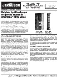
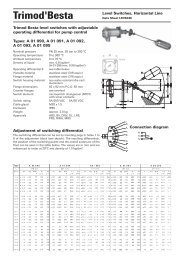
No <strong>535H</strong> Reduclng Regulator No <strong>536H</strong> Back Pressure Regulator<br />
Figure 1 - Typlcallnstallatlon<br />
-<br />
~<br />
.j",.:,.;.o;",I,~;,;;::""<br />
'~~:;:"'-,:.;!r;i:...,:~~ 'o..<br />
,c"""no:c~~' ,,,<br />
:""'c :!i,:"'Oy;<br />
""'c"1!;:~~"""""""<br />
M a I n te n a n ce i':Jr\,(,j:I.~it.~,,~;,;4?~'\iJ,t,;,.-r:ì\!è<br />
lOW ~~<br />
NEEDlE V Al VE<br />
EQUAUZJNG<br />
VAlVE<br />
No <strong>535H</strong>-SO or <strong>536H</strong>-SO -<br />
Dlfferentlal<br />
Pressure Regulator<br />
If there is excessive leakag~ throughthe regulatorwhen 2- Normal wear of seatting ~urfaces: disassemble and<br />
it is shutQff, the cause may be: replace plug and/or seat rmg.<br />
1- Foreig~ matter holding regulator off seat: disas- 3- Seat ~ing gasket (23) damaging (on/y on quid< chansemble<br />
and clean. g8 tnm regulators): replace gasket.<br />
3
Body SIA disassembly . Remove plug (3) and plug stem (4) tram the bonnet (6).<br />
: ~:d "(ì<br />
Nos <strong>535H</strong> and <strong>535H</strong> <strong>50</strong> Regulators service damage. After determining the maintenance<br />
required, praceed to the appropriata section ot this ins-<br />
Threaded Trlm (Figure 2) truction book.<br />
. Disconned the controlline(s) at the diaphragm case. Nos <strong>536H</strong> and <strong>536H</strong> <strong>50</strong> Regulators I<br />
o Remove body stud nuts (15).<br />
. .<br />
o Fasten the aduator to a holstlng gear and, very slowly,<br />
Qulck-Change Trlm (Figure 4)<br />
pull out aduator, bonnet (6), plug (3) and plug stem . Disconnect the contraI line(s) at the diaphragm case<br />
tram the body.<br />
Note: "a new body gasket (16) is not available, care<br />
and conned a temporary supply air line.<br />
o Apply on the diaphragm sufficient pressure to open the .<br />
must be taken to preserve the old gasket for re-use. plug about 1 mm.<br />
SpiraI wound<br />
an<br />
flexitallic gaskets are standard in the<br />
- eslgn a IS recommen .<br />
<strong>535H</strong> d <strong>535H</strong> <strong>50</strong> d . nd n. . ded o Loosen stem locknuts (13), turn them down plug stem<br />
th t k t J tal"ed h ti. th la, and Iod< them together. With wrench applled aver Iock-<br />
a a new gas e Utt is disassembled. InS , eac me e regu ,or<br />
nuts, !urn plug stem out ot actuator sterno<br />
o Loosen stem Iod
.:, .<br />
4<br />
. 17<br />
L"C<br />
21<br />
7<br />
1<br />
10<br />
2<br />
1<br />
9<br />
6 8 3<br />
16 5 2<br />
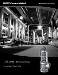
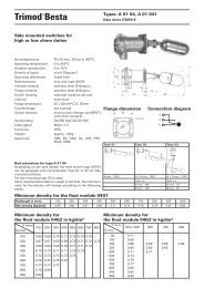
Figure 3<br />
3<br />
Qulck Change Trlm<br />
2 Model <strong>535H</strong> or <strong>535H</strong>-<strong>50</strong><br />
Regulator<br />
1 (Detall><br />
13<br />
14<br />
15<br />
Figure 2 13<br />
4<br />
Threaded Trlm<br />
Model <strong>535H</strong> or <strong>535H</strong>-<strong>50</strong> 7<br />
Regulator 1 10<br />
Figure 4<br />
Qulck Change Trlm<br />
Model <strong>536H</strong> or <strong>536H</strong>-SO<br />
Regulator 1<br />
1<br />
6<br />
1<br />
1<br />
3<br />
'*l$:'<br />
PARTS REFERENCE"'-'<br />
1 Body 9 Packing Flange Plug Guide Bushing (Incl. w/ref.. 6)<br />
2 Seat Ring 10 Packing Flange Nut Seria! Plate (Not Shown)<br />
3 Plug . 11 Packing Drive Sa'ew (Not Shown)<br />
4 Plug Stem 12 Packing Spaoor Packing Range Stud<br />
5 Plug Pin 13 Plug Stem Nut Cage.<br />
6 Bonnet 14 8ody Stud Seat Ring Gasket .<br />
7 Drive Nut 15 8ody Stud Nut<br />
8 Paoong Follower - . 16 Body Ga&ket<br />
. Rerommended spare parta<br />
. 0nIy OrI Q.lid< Change Trim Regulator<br />
,,' 5<br />
2<br />
.<br />
9
~<br />
Cautlon: When uslng heatlng devlces, Insure that o Insert two or three pieces of packing (11) into the pacpro<br />
per safety practlces ara observed. Such Items as king box to assist in guiding the stem and plug during<br />
the flammabl/lty and toxlclty of the controlled subtaken<br />
stance must ba consldered and proper precautlons<br />
. ,<br />
lapping.<br />
S d 'Il d d t d d 'ìth T h di<br />
o crew a rl e an appe ro w a - an e on to<br />
the plug stem and secure with a /ocknut. (See figure 5).<br />
r, "'.<br />
.<br />
Bushing Remaval Note: A5 an alternative, drill a hole through a tlat I<br />
The bushing (17) is a press fit into the bonnet and does pi9Ce ot 5teel and fasten to the plug stem u5ing two<br />
not normally raquire replacement. It may be pulled or locknuts.<br />
machined out. When machlning the bushing out, care be<br />
taken to maintain proper dimensions and tolerances.<br />
o Applying a slight pressure on the stem, rotate the stem<br />
in short oscillating strokes, 8 to 10 times,<br />
These will be fumlshed upon request.<br />
Lapping Seats<br />
Note: The plug 5hould be lifted and tumed 90° betore<br />
repeating pr9Ceding step. This intermittent lifting is<br />
. . . ,<br />
Lappl~g IS t,he process.of worklng the plug ag~lnst the<br />
required to keep the plug and seat ring concentric<br />
during lapping. .<br />
seat nng, wìth an abrasIVe, to produce a close filo When<br />
regulator leakage becomes excessive, lapping becomes o After completion of the lapping operation the seat ring<br />
necessary, The plug and seat ring seating surfaces and plug must be cleaned of alliapping compound in<br />
should be free of large scratches or dents and the preparation for reassembly.<br />
contact surfaces of the seats should be as narrow as<br />
possible. This may require dressing both parts in a lathe. aulck-Change Trlm<br />
The seat ~urf~ce of the plug is 28 degrees an? that.cf<br />
the seat nng IS 30 degrees, both tram centerllne axlS.<br />
O<br />
n<br />
Nos <strong>535H</strong> and <strong>535H</strong>-<strong>50</strong> Regulat r<br />
o S<br />
For the lapping operation, a good grade of fine grinding (Flgures 2& 3)<br />
compound is required. The compound should be mixed o Clean body gasket surface areas.<br />
with a small quantity of lubricant such as graphite. This '"<br />
will slow the cutting rate and prevent tearing of the sea- o Inst,a" a new seat rmg gasket (23) and Insert seat rlng<br />
ting surfaces. The amount of lapping required depends (2) In the body.<br />
on the materials, condition of seating surfaces and accu- Note: Gasket (23) Is temporarl/y placed to hold the<br />
r~
. ~,.,-~~<br />
.<br />
~<br />
.. .<br />
. Piace bonnet (6) on the body. . Insert two ~r ~hree.P!eces of packing into the packing<br />
C ti . 1 th t th t I (2) (22)<br />
- au on. nsure a e sea r ng , cage,<br />
( and bonnat (6) are properly allgned.<br />
. Uslng<br />
.<br />
4 OOdy , stud nuts (15), spaced equally apart, fas-<br />
ten the bonnet to the body usmg " only sllght pressure<br />
box to asslst m guldlng the stem and plug during lapin<br />
p g.<br />
. Screw a drilled and tapped !Od with a T -handle on to the<br />
pI st and ith 1 J,- ug em securew a~1 ut.(See ti ~ure5)<br />
.<br />
and tighten evenly. Note: As an alternative, dri// a ho/e through a f/at<br />
Ca ti Do t ti ht t t t Ifl<br />
tlons,<br />
u on<br />
at<br />
:<br />
thls tlrne.<br />
no<br />
The<br />
9 en<br />
bonnet<br />
nu s<br />
Is<br />
o<br />
used<br />
orque<br />
ten:lporarlly<br />
spec capiece<br />
of stee/ and fasten to the p/ug stem using two<br />
bcknuts.<br />
far guldlng purposes.<br />
I rt tw th ' f cki , . nse o or ree pleces o pa ng m<br />
t<br />
o<br />
th<br />
e pac<br />
ki<br />
ng<br />
. While to exert a lightly pulling on the stem, rotate it in<br />
short oscillating strokes 8 to 10 times,<br />
box to assist in guiding the stem and plug during lap- Note: The p/ug should be pu//ed out and turned 90°<br />
ping.<br />
. Screwa dn '1'-..1and t,,~<br />
~ ,.,<br />
rodw itha T' " andle to th<br />
"Il on e<br />
before repeating preceding step. This intermittent pu/-<br />
/ing is required to keep the pIug and seat tr' d . lap'<br />
ring concen-<br />
plug stem and secure with a bd
~ ~---~ ,<br />
. Unscrew the plug from the sterno (Counterclockwise.) Addlng Packlngs<br />
. Cut off the stem directly above the pin hole (Figure 6). To add a ring of packing, depressurize the regulator,<br />
. Re-thread the stem the originai amount. back off packing flange nuts (10) ali the way, lift the pac- ~ n<br />
king flange and follower and insert one ring of packing. "-"'<br />
Note: The apea of the plug siero marked 13 mm in TIghten nuts (10) finger tight plus one full turno<br />
figure 6 se/Ves as a guide and musi be checked to<br />
insure a close fit in the regulator plug. Body SIA Reassembly<br />
. Screw the stem solldly into the plug.<br />
. Piace the plug guide on a V-block and using a 3,5 mm After completion of the required maintenance the regulasize<br />
drill bit, drill the stem using the hole in the plug as tor should be re-assembled using the following proce- .<br />
a guide. dures:<br />
. Remove any burrs from the plug guide by making a Note: If any of the following steps were completed .<br />
slight counterbore. during maintenance, proceed to the next step.<br />
. Select the correct size pin, apply a small amount of<br />
grease on it, and press into the hole.<br />
On 535 H and <strong>535H</strong>-<strong>50</strong> Regulators<br />
Note: The pin musi be recessed approximate/y 1116"<br />
(1,5mm) belo w the plug guide surface.<br />
. After the plug has been pinned, it should be placed in<br />
Threaded Trim (Figure 2)<br />
. Clean ali gasketed surfaces.<br />
. Apply a small amount of sealant to the seat ring<br />
a lathe to insure it is running "true". If it is not, strike threads and sealing shoulder and installo<br />
the plug with a soft faced mallet to straighten.<br />
N A l h J h C PI ' L d AI<br />
ore: sea ani suc as o n rane ast/C ea IYO.<br />
Note: The siero should be placed in a co//et with the 2 is recommended or a sealant compatible with the<br />
plug guide against it and the plug should be struck. processo<br />
P k. B (F . 2 & 4) . Using seat ring wrench fabricated far removal, tighten ")<br />
ac Ing OX Igures seat ring only enough to insure a seal.<br />
Packlng Replacement Cautlon: Do not overtighten. Do not strlke seat<br />
rlng lugs. Thls could dlstort the seat rlng resultlng<br />
Packing box maintenance is one of the principle chores In unwarranted seat leakage.<br />
of routine se:vicing. 1ight~ess of the pac~ing. is m~intai- Note: Regulator should be lapped before final assemned<br />
by packlng compresslon. Compresslon IS achleved<br />
by evenly tightening the packing flange nuts (10) against<br />
bl S "L' t- Th aded tr.m-<br />
r. ee applng sea re I.<br />
the packing flange (9). . Carefully install plug and stem assembly.<br />
Care must be taken not to aver tighten as this could prev~nt<br />
.smooth operation of the regulator. If ali com.pre~ston<br />
.IS used ,up and the regulator leaks, new packlng IS<br />
. Install body gasket (16).<br />
. Install bonnet (6) and screw body stud nuts (15).<br />
Bonnet must be positioned so the packing flange<br />
requlred. studs afe at a right angle 70 the flow center fine.<br />
Cautlon: Regulator must be lsolated an the pressure TIghten nuts (15). .<br />
vented before performlng packlng box malntenance. Cautlon: Refer to figure 7 far proper bolt torque<br />
Proceed as follows :<br />
. Loosen and remove packing flange nuts (10).<br />
. Raise pad
- . .<br />
..' . i<br />
" -<br />
. Install packing flange stud nuts (1 O). . Insert four packing rings (11). then packing spacer (12)<br />
- Cautlon: Do noI overtlghten (See paragraph<br />
and two rings.<br />
:--MPacklng Box"). . Install packing follower (8) and packing flange (9).<br />
. Proceed lo the be~w paragraph instructions far actua- . Install packing flange stud nuts (10).<br />
tor to body assembly and plug stem adjustment.<br />
C au t I on: D o no t aver ti g ht en (S ee paragrap<br />
h<br />
"Packlng Box").<br />
Qulck-Change Trlm (Flgures 2 & 3) . Proceed to the below paragraph <strong>Instruction</strong>s far adua-<br />
. Clean ali gasketed surfaces.<br />
. Install seat ring gasket (23) and seat ring (2).<br />
tor to body assembly and plug stem adjustment.<br />
.Install cage (22). Actuator to Body Assembly and<br />
, . Carefully install plug and stem assembly. Plug Stem Adjustment<br />
Note: Regulator should be lapped before fina! assem-<br />
. bfy. 5ee -Lapping seat-Quick-Change trim-.<br />
'Install body gasket (16). On 535 H and <strong>535H</strong>-<strong>50</strong> Regulat~rs<br />
. Install bonnet (6) and screw body stud nuts (15). . Hold actuator above body SIA. Before that actuator<br />
BQnnet musi be positioned so the packing flange stem contact the plug stem, screw the two nuts (13) lo<br />
studs are at a righi angle to the flow center llne. the threaded end of plug stem and piace the drive nut<br />
lighten nuts (15). (7) on the actuator yoke.<br />
Cautlon: Care musI be taken to assure that the . While holding the plug in -Open- position, slowly pull<br />
cage, seat and bonnet are properly allgned In the down the actuator and screw the plug stem into the<br />
body. Refer to figure 7 far proper bolt torque and actuator stem.<br />
tlghtenlng sequence speclflcatlons. '<br />
Note: Thls operatlon wlll be facliltated tumlng the<br />
.Insert four packing rings (11), then packing spacer (12) plug stem by means of a wrench applled on the<br />
and two rings. nuts (13) tlghtened one agalnst the other.<br />
. Install packing follower (8) and packing flange (9). Carefully avold that seatlng surface of the plug<br />
. Install packing flange stud nuts (10). contact the seat rlng durlng the plug screwlng.<br />
C ti D t ti ht (S h - Pulling down motlon of the actuator and plug stem<br />
..:uck~n:B o,,~o aver g en ee paragrap screwlng musi be slmultaneously performed:<br />
a ng ox . carry on untll the lower parI of actuator yoke<br />
. Proceed to the belowparagraph instructions far actua- contact the bonnet (6).<br />
Ior to body assembly and plug stem adjustment. . PI ace th e a d ua t or . In th e corre d pos 'n ° IOn. Screw and<br />
On 536 H and <strong>536H</strong>-SO Regulators Ig. 4<br />
. . Clean body gasket surface areas.<br />
(Fi )<br />
tighten the drive nut (7).<br />
. Turn plug stem into actuator stem as far as it will goo<br />
. Connect the controlled pressure line(s) to diaphragm<br />
. . Apply slightly more pressure to diaphragm actuator<br />
. Insert the stem and plug assembly Into the body and than spring is set foro<br />
.. put it on the bottom.<br />
. Turn plug stem out of aduator stem until plug is sea-<br />
. Install a new seat ring gasket (23) and insert seat ring ledo<br />
(2) in the body.<br />
case.<br />
. . Relieve diaphragm pressure and turn plug stem out of<br />
Note: Regulato.r should be.lapped befor.e fina! assem- aduator stem one fuI! turn more.<br />
bfy. 5ee -Lapplng seat-Qulck-Change t"m-.<br />
I Il bod k (16) . Lod< stems with Iocknuts (13).<br />
. nsta y gas et .<br />
. Placo back in service and tighten the packing flange<br />
. Insert the cage (22) iAto the body. nuts (10) only as much as is necessary to stop any<br />
. Slide the bonnet (6) on the plug stem, then piace it on leakage.<br />
1.he cage and the body.<br />
Cautlon: Insure that the seat rlng (2), cage (22),<br />
and bonnet (6) are properly allgned. ,".'<br />
. Screw body stud nuts (15). Bonnet musi be positioned On 536 H and <strong>536H</strong>-<strong>50</strong> Regulators<br />
so the packing flange studs are al a righi angle lo the . Hold actuator above body SIA. Before that actuator<br />
flow center Une. Tighten nuts (15). stem contact the plug stem, screw the two nuts (13) to<br />
Cautlon: Refer to figure 7 for pro per bolt torque the threaded end of plug stem and piace the drive nut ~",<br />
and tlghtenlng sequence speclflcatlons. (7). on the actuator yoke. .<br />
,..<br />
c_-
.. .-. l''''<br />
"<br />
. ~Iowly pull down the actuator and screw the plug stern . Connect a pressure line to upper diaphragrn case<br />
Into the actuator sterno .<br />
Note: Thls operatlon wlll be facllltated turnlng the . Apply sufficient pressure to upper diaphragrn case to ~<br />
plug stem by means of a wrench applled on the rnove plug off seat. ,<br />
nuts (13) tlghtened one agalnst the other. "-'-<br />
Carefully avold that seatlng surface of the plug . Turn plug stern one full turn into actuator sterno<br />
contact the seat rlng durlng the plug screwlng. . .<br />
-Pulling down motlon of the actuator and plug stem . Screw and tlghten nuts (13) agalnst the actuator sterno<br />
screwlng musI be slmultaneously performed:<br />
carry on unIti the lower parI of actuator yoke<br />
contact the bonnet (6).<br />
. Piace the actuator in the correct position. Screw and<br />
tighten the drive nut (7). . . Scre~ the plug stern mto the actuator stern until the<br />
Lock by rneans of a wrench applied on the nuts.<br />
. Connect the controlled pressure line(s) to diaphragrn<br />
case.<br />
. Piace back . In servlce . and tlghten . the packing flan e<br />
nuts (10) only as much as is necessary to stop a~y<br />
plug IS seated. leakage. "<br />
Masoneilan ITALY I Masoneilan~~ii ~ é<br />
- f;;,<br />
Headquarters Via Cassa no 77, 80020 Casavatore (Napoli) . Tel. 7892111 h<br />
Works & Atter sale service Telex: 710084 - Facsimile: (081) 7382922 - Cable: Masonica - Casavatore ";<br />
,iO,<br />
Sales office C.so Garibaldi 113, 20121 Milano - Tel. (02) 29.005.6<strong>50</strong> - Telex: 314231 :<br />
North Italy Facsimile: (02) 29.005.660<br />
Ooc. Ted\niq.. MN - Condé - DESK1OP PUBLISHING. . ~j:':r i Janu.y 1991<br />
.;:';.:;: ,::\;~;-,:::",:,;!~,,"; " .,;.<br />
"'~Ir,k' """,?~",.!~,~"""","",i[c"('!i."..l,~~~.. "'ti?'<br />
": ..;c",,':' "~,.."rc,."..,. "",;~~r",,;.. 'Cc.'<br />
- -<br />
I~<br />
.<br />
.<br />
.