Operating manual VA 300 Mobile flow and air - CS Instruments
Operating manual VA 300 Mobile flow and air - CS Instruments
Operating manual VA 300 Mobile flow and air - CS Instruments

You also want an ePaper? Increase the reach of your titles
YUMPU automatically turns print PDFs into web optimized ePapers that Google loves.
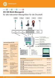
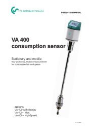
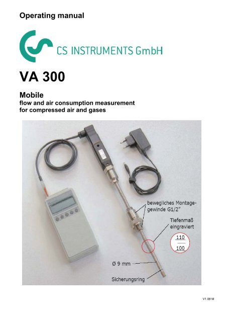
<strong>Operating</strong> <strong>manual</strong><br />
<strong>VA</strong> <strong>300</strong><br />
<strong>Mobile</strong><br />
<strong>flow</strong> <strong>and</strong> <strong>air</strong> consumption measurement<br />
for compressed <strong>air</strong> <strong>and</strong> gases<br />
V1.08 M
Important information<br />
The operating instructions must be read in full <strong>and</strong> carefully observed before<br />
starting up the device.<br />
The manufacturer cannot be held liable for any damage which occurs as a result<br />
of non-observance or non-compliance with this <strong>manual</strong>.<br />
Should the device be tampered with in any manner other than a procedure which<br />
is described <strong>and</strong> specified in the <strong>manual</strong>, the warranty is cancelled <strong>and</strong> the<br />
manufacturer is exempt from liability.<br />
The device is destined exclusively for the described application.<br />
<strong>CS</strong> <strong>Instruments</strong> offers no guarantee for the suitability for any other purpose <strong>and</strong> is<br />
not liable for errors which may have slipped into this operating <strong>manual</strong>. They are<br />
also not liable for consequential damage resulting from the delivery, capability or<br />
use of this device.<br />
Area of application<br />
The <strong>CS</strong> <strong>VA</strong> <strong>300</strong> product range is designed for stationary <strong>and</strong> mobile use in<br />
compressed <strong>air</strong> pipes, <strong>air</strong> ducts or shafts.<br />
It is used for the measurement <strong>and</strong> control of <strong>flow</strong> <strong>and</strong> <strong>air</strong> consumption in<br />
operating <strong>air</strong> pressure <strong>and</strong> other gases.<br />
The principle of measurement is based on the evacuation of heat from an<br />
electrically heated sensor into the surrounding <strong>air</strong> <strong>flow</strong>.<br />
The measuring devices operate independently of pressure <strong>and</strong> temperature.<br />
When the sensor is fitted in a pipe, the output signal from the speed of <strong>flow</strong> is<br />
used to calculate the st<strong>and</strong>ard volume at 20 °C <strong>and</strong> 1000 mbar of the medium.<br />
2
Safety instructions<br />
Must be read before starting up the device!<br />
Warning:<br />
• Do not exceed the pressure range of 50 bar.<br />
• Installation under pressure up to 16 bar is possible without mounting device.<br />
When the pressure is between 16 <strong>and</strong> 50 bar it is needed to use the<br />
mounting device.<br />
• Observe the measuring range of the sensor.<br />
• Overheating destroys probes.<br />
• Observe permissible storage, transport <strong>and</strong> operating temperatures.<br />
• Improper h<strong>and</strong>ling or use of force when opening the device cancels all<br />
warranty claims.<br />
• Adjustment <strong>and</strong> calibration work must only be carried out by trained<br />
personnel from the field of measuring <strong>and</strong> control engineering.<br />
• Always observe the direction of <strong>flow</strong> when positioning the sensor.<br />
• The safety ring on the sensor head must always remain undamaged <strong>and</strong> sit<br />
correctly in the intended groove.<br />
• The screwed fixture must be pressure tight.<br />
• The adapter sleeve must be tightened with a torque of 20 ... 30 Nm.<br />
• Avoid condensation on the sensor element or water drops in the measuring<br />
<strong>air</strong> at all costs as they cause faulty measuring results.<br />
• The values of the inlet <strong>and</strong> outlet sections must not fall below the specified<br />
minimum values as this causes increased deviations in the measuring<br />
results.<br />
3
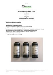
Determining the point of installation<br />
In order to maintain the accuracy stipulated in the data sheets, the sensor must be<br />
inserted in the centre of a straight pipe section with unhindered <strong>flow</strong><br />
characteristics.<br />
Unhindered <strong>flow</strong> characteristics are achieved if the sections in front of the sensor<br />
(inlet) <strong>and</strong> behind the sensor (outlet) are sufficiently long, absolutely straight <strong>and</strong><br />
lack obstructions such as edges, seams, curves etc.<br />
Careful attention must be paid to the design of the outlet section as obstructions<br />
can cause counter-<strong>flow</strong> turbulence as well as turbulence in the direction of the<br />
<strong>flow</strong>.<br />
D<br />
<strong>flow</strong><br />
L<br />
L 1 L 2<br />
L = Length of the entire measurement section<br />
L1 = Length of inlet section<br />
L2 = Length of outlet section<br />
D = Diameter of measurement section<br />
4<br />
D/2 D/2<br />
The following table shows the equalising sections necessary in relation to existing<br />
obstructions.<br />
D/2 D/2
Table of inlet <strong>and</strong> outlet sections<br />
Flow obstruction<br />
before the measurement section<br />
Slight curve<br />
(bend < 90°)<br />
Reduction<br />
(Tube narrows towards measurement<br />
section)<br />
Expansion<br />
(Rohr exp<strong>and</strong>s towards measurement<br />
section)<br />
90° bend<br />
or T piece<br />
2 x 90° bends<br />
on one level<br />
2 x 90° bends<br />
3 dimensional change of direction<br />
Shut-off valve<br />
5<br />
Min. length<br />
inlet (L1)<br />
Min. length<br />
outlet (L2)<br />
12 x D 5 x D<br />
15 x D 5 x D<br />
15 x D 5 x D<br />
15 x D 5 x D<br />
20 x D 5 x D<br />
35 x D 5 x D<br />
45 x D 5 x D<br />
The respective minimum values required are indicated here.<br />
If it is not possible to observe the stipulated equalising sections, considerable<br />
deviations in measuring results must be expected.<br />
Installation position<br />
The sensor head must sit in the centre of the pipe.<br />
Observe the direction of <strong>flow</strong> indicated on the tip of the sensor.
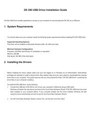
Measurement section for <strong>VA</strong> <strong>300</strong> probes<br />
LA<br />
G 1/2"-outer screw neck<br />
Outer thread: G x Outer thread: G x<br />
30 mm 30 mm<br />
Total length<br />
Strömungsrichtung / Direction of <strong>air</strong> <strong>flow</strong><br />
Outer dia.<br />
DA Length LA<br />
Thread<br />
G x Pipe<br />
21.3 mm 350 mm G 1/2" 21.3 * 2.6 mm, Stahl 1.4301<br />
26.9 mm<br />
33.7 mm<br />
42.4 mm<br />
48.3 mm<br />
60.3 mm<br />
76.1 mm<br />
430 mm<br />
530 mm<br />
660 mm<br />
750 mm<br />
930 mm<br />
G 3/4"<br />
G 1"<br />
G 1 1/4"<br />
G 1 1/2"<br />
G 2"<br />
1170 mm G 2 1/2 "<br />
26.9 * 2.6 mm, Stahl 1.4301<br />
33.7 * 3.2 mm, Stahl 1.4301<br />
42.4 * 3.2 mm, Stahl 1.4301<br />
48.3 * 3.2 mm, Stahl 1.4301<br />
60.3 * 3.6 mm, Stahl 1.4301<br />
76.1 * 3.6 mm, Stahl 1.4301<br />
LA<br />
G 1/2"-outer screw neck<br />
Length: L1<br />
6<br />
Total length<br />
500 mm<br />
600 mm<br />
750 mm<br />
900 mm<br />
1000 mm<br />
1250 mm<br />
1500 mm<br />
Measurement section for <strong>VA</strong> <strong>300</strong> probes with flange connection<br />
= DA<br />
Weld neck flange acc. to DIN 2633 Weld neck flange acc. to DIN 2633<br />
Strömungsrichtung / Direction of <strong>air</strong> <strong>flow</strong><br />
Outer dia.<br />
DA Length L1 LA DIN - flange Pipe<br />
88.9 mm 1750 mm 1330 mm DN 80 / 88.9 88.9 * 2.0 mm, Stahl 1.4301<br />
114.3 mm<br />
139.7 mm<br />
168.3 mm<br />
2000 mm<br />
2750 mm<br />
<strong>300</strong>0 mm<br />
1700 mm<br />
2050 mm<br />
2450 mm<br />
Total length = L1 + 2 * DIN-flange<br />
DN 100 / 114.3<br />
DN 125 / 139.7<br />
DN 150 / 168.3<br />
114.3 * 2.0 mm, Stahl 1.4301<br />
139.7 * 3.0 mm, Stahl 1.4301<br />
168.3 * 3.0 mm, Stahl 1.4301<br />
DA<br />
DA<br />
Total length<br />
= L1 + 2 * DIN flange<br />
1750 + (2*50) = 1850 mm<br />
2000 + (2*52) = 2104 mm<br />
2750 + (2*55) = 2860 mm<br />
<strong>300</strong>0 + ( 2*55) = 3110 mm
Assembly instructions<br />
Safety information must be observed.<br />
Assembly is carried out by inserting the connection thread (1/2“ thread, SW 27)<br />
into the connection piece.<br />
The sensor is then inserted to the required immersion depth <strong>and</strong> aligned<br />
according to the direction of <strong>air</strong> <strong>flow</strong>.<br />
A depth gauge engraved on the probe tube will assist you, along with a <strong>flow</strong><br />
alignment arrow <strong>and</strong> an aligning aid.<br />
Once the sensor has been aligned, the adapter sleeve must be tightened with the<br />
stipulated torque (SW 17).<br />
Attention: Alignment of the sensor must not be modified when tightening the<br />
connection thread <strong>and</strong> adapter sleeve.<br />
If this should occur, check the immersion depth <strong>and</strong> alignment again <strong>and</strong> correct if<br />
necessary.<br />
The angular deviation should not be greater than +- 2° in relation to the ideal<br />
position as otherwise the measuring accuracy will decrease.<br />
Commissioning<br />
The valid measuring range <strong>and</strong> delivery configuration are programmed by the<br />
manufacturer on the basis of the user’s specifications.<br />
The mobile <strong>flow</strong> <strong>and</strong> <strong>air</strong> consumption measuring devices from the <strong>VA</strong> <strong>300</strong> series<br />
function according to the “plug <strong>and</strong> play” principle. The device is ready for<br />
operation as soon as the power supply is connected.<br />
Modifications to the measuring ranges can be carried out with the <strong>CS</strong>2390-5<br />
h<strong>and</strong>held instrument.<br />
With mobile <strong>flow</strong> <strong>and</strong> <strong>air</strong> consumption measuring devices, the user will be able to<br />
carry out these modifications using the software <strong>and</strong> RS232 interface.<br />
7
Flow measuring ranges<br />
Inner diameter St<strong>and</strong>ard version<br />
Max. version<br />
<strong>VA</strong> <strong>300</strong> - 80<br />
<strong>VA</strong> <strong>300</strong> - 120<br />
Inch mm Measuring range<br />
Measuring range<br />
from ... to<br />
from ... to<br />
1/4“ 6 0.8 ... 80 l/min 1.0 ... 110 l/min<br />
1/2“ 16.1 2.5 ... 760 l/min 3.5 ... 1100 l/min<br />
3/4“ 21.7 0.3 ... 90 m³/h 0.4 ... 120 m³/h<br />
1“ 27.3 0.5 ... 150 m³/h 0.6 ... 200 m³/h<br />
1 1/4“ 36.0 0.9 ... 280 m³/h 1.2 ... 360 m³/h<br />
1 1/2“ 41.9 1.2 ... 370 m³/h 1.5 ... 500 m³/h<br />
2“ 53.1 2 ... 600 m³/h 2.5 ... 800 m³/h<br />
2 1/2“ 71.1 3.5 ... 1100 m³/h 5 ... 1500 m³/h<br />
3“ 84.9 5 ... 1600 m³/h 7 ... 2200 m³/h<br />
4“ 110.3 9 ... 2700 m³/h 12 ... 3600 m³/h<br />
5“ 133.7 13 ... 4000 m³/h 18 ... 5<strong>300</strong> m³/h<br />
6“ 162.3 18 ... 5800 m³/h 25 ... 8000 m³/h<br />
8“ On request On request<br />
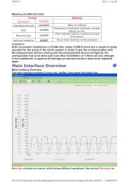
Drawing of <strong>VA</strong> <strong>300</strong> probe<br />
8
Short instruction for portable applications with <strong>CS</strong> 2390-5 <strong>and</strong> <strong>VA</strong> <strong>300</strong><br />
There is a special version of <strong>VA</strong> <strong>300</strong> probe which is used to co-operate with <strong>CS</strong> 2390-5 h<strong>and</strong><br />
held meter. Stationary probes <strong>VA</strong> <strong>300</strong> cannot be connected to this instrument.<br />
Measurement values are always referenced to 20 °C und 1000 mbar.<br />
The portable probes can be mounted in any compressed <strong>air</strong> tube by considering the details<br />
from chapter XXX. They will measure the volume <strong>flow</strong> in m³/h depending on the tube diameter<br />
setting in the h<strong>and</strong> held instrument <strong>CS</strong> 2390-5.<br />
Start of measurement<br />
1. Plug in the supplied mains adapter <strong>and</strong> connect it to the mains supply.<br />
Attention:<br />
The operation of the portable probes <strong>VA</strong> <strong>300</strong> (3<strong>300</strong>.0081 <strong>and</strong> 3<strong>300</strong>.0121) is only possible<br />
by using the <strong>CS</strong>2390-5 with mains supply (2390.2290) or the optional battery pack<br />
(0515.1002).<br />
2. Mount probe into the compressed <strong>air</strong> pipe as described in this instruction <strong>manual</strong>.<br />
3. Connect <strong>VA</strong> <strong>300</strong> probe with supplied cable to one of the left probe input of <strong>CS</strong> 2390-5<br />
(M0, M1, M2). Left connector M0, mid M1 right M2, recommended channel is left M0.<br />
4. Switch on instrument (sliding switch left).<br />
5. Display will show the actual value in m³/h. IN case display shows 0 ---- the probe has been<br />
connected to either MA or M2. Use the key M▲ to select the desired channel.<br />
6. If the display is flashing, the inner diameter is set to DN = 0. Please enter the correct inner<br />
diameter of the tube as described under 7.<br />
7. Entering the inner diameter (only possible when m³/h is shown in the Display):<br />
Default setting ex factory:<br />
2" = 53,1 mm<br />
Other diameters are entered as follows:<br />
• Press FUNCTION key, display shows 0: 053.1 DN.<br />
• Press PROG (►) once 053.1 First digit is flashing<br />
• Use PROG (►) to select the digit to be changed (digit flashes).<br />
• Use the keys (▼) <strong>and</strong> (▲) to enter the desired number.<br />
• Press PROG (►) until all numbers are entered <strong>and</strong> no digit is flashing anymore.<br />
• Press M▲ once. Now the instrument is ready to measure based on the newly entered<br />
diameter. The diameter remains set even when the instrument is powered off.<br />
9
Further menu points:<br />
1. Switch from volume <strong>flow</strong> to velocity<br />
By pressing the key M▲ the display will change from m³/h to m/sec which is the velocity at the<br />
point of measurement.<br />
2. Check memory status, screen displays SF 31,1:<br />
Press FUNCTION key, screen displays 31,1 SF, up to 3600 individual measured values are<br />
possible.<br />
Delete memory for new measurement with PROG (►) key. SCLR SF flashes on the screen<br />
Delete memory by pressing M▲ CLEAR, <strong>and</strong> press M▲ CLEAR again to return to<br />
measurement menu<br />
3. Alter ZY storage cycle:<br />
Press FUNCTION key, the factory setting is a cycle of 00:00:05 ZY, which means that a<br />
measured value is stored every 5 seconds. Alterations are made using PROG (►) <strong>and</strong> (▲)(▼)<br />
number keys. Store with PROG (►) key until no figures are flashing. Return to measurement<br />
with M▲ key.<br />
4. Storing measured values<br />
Store measured values via Start key. (▲)(▲) appears in the display<br />
Storage is stopped via Stop key.<br />
Additional considerations:<br />
Do not change the connected probes as long you have recorded data stored inside the<br />
instrument. The instrument cannot distinguish between different probes <strong>and</strong> will always assume<br />
to have the same probes connected as at the start of the first record. Whenever probes have to<br />
be changed we recommend to transfer the recorded data to the PC via <strong>CS</strong>-Soft <strong>and</strong> then clear<br />
the internal memory.<br />
5. Read out recorded data, analyze them with <strong>CS</strong>Soft Software<br />
Connect RS-232 cable to the right h<strong>and</strong> connector (black A1)of <strong>CS</strong>2390 <strong>and</strong> connect the other<br />
end to the COM port of your PC. Start <strong>CS</strong>-Soft by clicking the icon on the desktop. Please find<br />
further instructions in the tutorial of <strong>CS</strong>-Soft.<br />
If the <strong>CS</strong> 2390 is connected with a PC it is not possible to change the diameter or other<br />
settings.<br />
10
Measuring ranges in relation to inner pipe diameter<br />
This table is used when the st<strong>and</strong>ard <strong>VA</strong> <strong>300</strong>-80 probe is to be used in different pipes.<br />
Inner pipe<br />
diameter<br />
Volume <strong>flow</strong><br />
(final value of meas. range) max.<br />
Inch mm m³/h m³/min l/min l/s m/s<br />
1/4" 6.0 4.7 0.08 78.7 1.31 92.7<br />
10.0 15.1 0.25 251.1 4.19 92.7<br />
15.0 38.9 0.65 648.6 10.81 92.7<br />
1/2" 16.1 45.6 0.76 760.8 12.68 92.7<br />
3/4" 21.7 89.1 1.48 1484.9 24.75 92.7<br />
1" 25.0 122.2 2.04 2036.3 33.94 92.7<br />
26.0 132.9 2.21 2214.3 36.90 92.7<br />
27.3 147.5 2.46 2457.5 40.96 92.7<br />
28.5 162.0 2.70 2699.6 44.99 92.7<br />
30.0 180.9 3.01 3014.8 50.25 92.7<br />
1 1/4" 32.8 218.8 3.65 3646.2 60.77 92.7<br />
36.0 266.3 4.44 4437.6 73.96 92.7<br />
36.3 270.7 4.51 4511.9 75.20 92.7<br />
1 1/2" 39.3 320.1 5.34 5335.7 88.93 92.7<br />
40.0 332.5 5.54 5541.4 92.36 92.7<br />
41.9 366.7 6.11 6111.0 101.8 92.7<br />
43.1 389.4 6.49 6490.4 108.1 92.7<br />
45.8 441.9 7.37 7365.7 122.7 92.7<br />
2" 50.0 530.6 8.84 8844.1 147.4 92.7<br />
51.2 557.1 9.29 9285.1 154.7 92.7<br />
53.1 600.0 10.00 10000 166.6 92.7<br />
54.5 632.8 10.55 10546 175.7 92.7<br />
57.5 707.8 11.80 11797 196.6 92.7<br />
60.0 773.6 12.89 12892 214.8 92.7<br />
64.2 888.9 14.81 14814 246.9 92.7<br />
11
Measuring ranges in relation to inner pipe diameter<br />
This table is used when the st<strong>and</strong>ard <strong>VA</strong> <strong>300</strong>-80 probe is to be used in different pipes.<br />
Inner pipe<br />
diameter<br />
Volume <strong>flow</strong><br />
(final value of meas. range) max.<br />
Inch mm m³/h m³/min l/min l/s m/s<br />
2 1/2" 65.0 913.5 15.22 15224 253.7 92.7<br />
70.3 1071.1 17.85 17851 297.5 92.7<br />
71.1 1095.6 18.26 18260 304.3 92.7<br />
76.1 1258.2 20.97 20969 349.4 92.7<br />
3" 80.0 1390.4 23.17 23173 386.2 92.7<br />
81.0 1425.4 23.76 23756 395.9 92.7<br />
82.5 1480.5 24.67 24674 411.2 92.7<br />
84.9 1569.8 26.16 26162 436.0 92.7<br />
90.0 1766.1 29.44 29435 490.6 92.7<br />
4" 100.0 2183.1 36.38 36384 606.4 92.7<br />
107.1 2507.1 41.78 41784 696.4 92.7<br />
110.0 2644.7 44.08 44077 734.6 92.7<br />
5" 125.0 3423.3 57.1 57055 950.9 92.7<br />
133.7 3921.1 65.4 65351 1089.2 92.7<br />
6" 150.0 4941.4 82.4 82356 1372.6 92.7<br />
159.3 5579.8 93.0 92996 1549.9 92.7<br />
182.5 7323.4 122.1 122055 2034.3 92.7<br />
190.0 7947.1 132.5 132451 2207.5 92.7<br />
8" 200.0 8816.2 146.9 146936 2448.9 92.7<br />
206.5 9398.5 156.6 156642 2610.7 92.7<br />
10" 250.0 13775 229.6 229587 3826.5 92.7<br />
260.4 14945 249.1 249086 4151.4 92.7<br />
12" <strong>300</strong>.0 19836 330.6 330606 5510.1 92.7<br />
309.7 21139 352.3 352331 5872.2 92.7<br />
339.6 25418 423.6 423646 7060.8 92.7<br />
388.8 33317 555.3 555291 9254.9 92.7<br />
500.0 55101 918.4 918350 15305 92.7<br />
600.0 79345 1322 1322424 22040 92.7<br />
700.0 107998 1800 1799966 29999 92.7<br />
800.0 141058 2351 2350976 39182 92.7<br />
900.0 178527 2975 2975455 49590 92.7<br />
1000.0 220404 3673 3673401 61223<br />
12<br />
92.7
Measuring ranges in relation to inner pipe diameter<br />
This table is used when the <strong>VA</strong> <strong>300</strong>-120 probe (maximun version) is to be used in different<br />
pipes.<br />
Inner pipe<br />
diameter<br />
Volume <strong>flow</strong><br />
(final value of meas. range) max.<br />
Inch mm m³/h m³/min l/min l/s m/s<br />
1/4" 6,0 6,3 0,10 105,0 1,75 123,7<br />
10,0 20,1 0,33 334,8 5,59 123,7<br />
15,0 51,9 0,86 864,8 14,4 123,7<br />
1/2" 16,1 60,8 1,01 1012 16,9 123,7<br />
3/4" 21,7 118,8 1,98 1980 33,0 123,7<br />
1" 25,0 162,9 2,72 2715 45,3 123,7<br />
26,0 177,2 2,95 2952 49,2 123,7<br />
27,3 196,6 3,28 3277 54,6 123,7<br />
28,5 215,9 3,60 3407 60,0 123,7<br />
30,0 241,2 4,02 4020 67,0 123,7<br />
1 1/4" 32,8 291,7 4,86 4862 81,0 123,7<br />
36,0 355,0 5,92 5917 98,6 123,7<br />
36,3 359,6 5,94 5925 99,0 123,7<br />
1 1/2" 39,3 426,9 7,11 7114 118,6 123,7<br />
40,0 443,3 7,39 7389 123,1 123,7<br />
41,8 486,5 8,11 8109 135,2 123,7<br />
43,1 519,2 8,65 8654 144,2 123,7<br />
45,8 588,5 9,81 9809 163,6 123,7<br />
2" 50,0 706,6 11,78 11778 196,3 123,7<br />
51,2 742,8 12,38 12380 206,3 123,7<br />
53,1 800,0 13,33 13333 222,2 123,7<br />
54,5 844,9 14,08 14081 234,6 123,7<br />
57,5 945,1 15,75 15751 262,5 123,7<br />
60,0 1032,8 17,21 17213 286,8 123,7<br />
64,2 1186,8 19,78 19779 329,6 123,7<br />
13
Measuring ranges in relation to inner pipe diameter<br />
This table is used when the <strong>VA</strong> <strong>300</strong>-120 (maximun version) probe is to be used in different<br />
pipes.<br />
Meßrohr<br />
Innendurchmesser<br />
Volumenstrom<br />
(Meßbereichsendwert) max.<br />
Zoll mm m³/h m³/min l/min l/s m/s<br />
2 1/2" 65,0 1218,0 20,30 20<strong>300</strong>,4 338,34 123,7<br />
70,3 1428,2 23,80 23803,6 396,73 123,7<br />
71,1 1460,9 24,35 24348,4 405,81 123,7<br />
76,1 1677,7 27,96 27960,9 466,01 123,7<br />
3" 80,0 1854,0 30,90 30900,2 515,00 123,7<br />
81,0 1900,7 31,68 31677,6 527,96 123,7<br />
82,5 1974,1 32,90 32901,3 548,36 123,7<br />
84,9 2093,1 34,89 34885,5 581,42 123,7<br />
90,0 2355,0 39,25 39249,8 654,16 123,7<br />
4" 100,0 2910,9 48,51 48514,8 808,58 123,7<br />
107,1 3342,9 55,72 55715,4 928,59 123,7<br />
5" 125,0 4564,7 76,1 76077,8 1268,0 123,7<br />
133,7 5228,4 87,1 87140,6 1452,3 123,7<br />
6" 150,0 6588,9 109,8 109814,4 1830,2 123,7<br />
159,3 7440,1 124,0 124001,5 2066,7 123,7<br />
182,5 9765,0 162,8 162750,0 2712,5 123,7<br />
190,0 10584,1 176,4 176401,6 2940,0 123,7<br />
8" 200,0 11727,5 195,5 195458,8 3257,6 123,7<br />
206,0 12441,7 207,4 207362,3 3456,0 123,7<br />
206,5 12502,2 208,4 208370,1 3472,8 123,7<br />
260,4 19928,0 332,1 332133,4 5535,6 123,7<br />
12" <strong>300</strong>,0 26449,9 440,8 440831,9 7347,2 123,7<br />
309,7 28188,0 469,8 469799,9 7830,0 123,7<br />
339,6 33893,6 564,9 564892,6 9414,9 123,7<br />
388,8 44425,7 740,4 740428,4 12340,5 123,7<br />
500,0 73472,0 1224,5 1224533,1 20408,9 123,7<br />
600,0 105799,7 1763,3 1763327,7 29388,8 123,7<br />
700,0 144005,1 2400,1 2400084,9 40001,4 123,7<br />
800,0 188088,3 3134,8 3134804,8 52246,7 123,7<br />
900,0 238049,2 3967,5 3967487,3 66124,8 123,7<br />
1000,0 293888,0 4898,1 4898132,5 81635,5 123,7<br />
14
Technical data<br />
Measur<strong>and</strong>s: m³/h<br />
m/s<br />
(The underlying st<strong>and</strong>ard is valid:<br />
DIN 1945. ISO 1217 at 20°C <strong>and</strong> 1000 mbar)<br />
measuring range: see table<br />
Principle of measurement: calorimetric measurement<br />
Sensor: 2 x PT100<br />
Measuring medium: Air, gas<br />
<strong>Operating</strong> temperature: -30 to 140°C probe tube<br />
-30 to 80 °C housing<br />
<strong>Operating</strong> pressure: up to 50 bar<br />
Analogue output: 4 to 20 mA for m³/h<br />
Pulse output: 1 pulse per m³<br />
(High signal 24 VDC 2ms)<br />
Power supply: 230 VDC. 50 to 60 Hz<br />
(stationary with <strong>flow</strong> processor )<br />
Power supply: 24 VDC smoothed ± 15%<br />
(mobile, probe only)<br />
Accuracy: ± 3% of m.v.<br />
With measurement section ± 2% of m.v. (option via 5 point ISO precision calibration)<br />
This data is only valid in relation to the measurement section<br />
Accuracy: ± 4 % of m.v.<br />
Without measurement section ± 3 % of m.v. (option via 5 point ISO precision calibration)<br />
This data is only valid when the correct inner diameter<br />
is entered.<br />
Display: Flow in m³/h<br />
Velocity in m/s<br />
Selectable units: m³/h (st<strong>and</strong>ard factory setting)<br />
m³/min. l/min. l/s. ft/min. cfm<br />
15
Service information<br />
Maintenance<br />
The sensor head should be checked regularly for dirt <strong>and</strong> cleaned if necessary.<br />
Should dirt, dust or oil build up on the sensor element, a deviation will occur in the<br />
measured value.<br />
A yearly check is recommended. Should the compressed <strong>air</strong> be heavily soiled, this<br />
interval must be shortened.<br />
Cleaning the sensor head<br />
The sensor head can be cleaned by carefully moving it to <strong>and</strong> fro in warm water<br />
with a small amount of washing up liquid. Avoid physical intervention on the<br />
sensor (e.g. using a sponge or brush).<br />
If soiling cannot be removed, service <strong>and</strong> maintenance must be carried out by the<br />
manufacturer.<br />
Re: calibration<br />
If no customer specifications are given, then we recommend that calibration is<br />
carried out every 12 months. The sensor must be sent to the manufacturer for this<br />
purpose.<br />
Spare parts <strong>and</strong> rep<strong>air</strong><br />
Spare parts are not available for reasons of measuring accuracy.<br />
If parts are faulty, they must be sent to the supplier for rep<strong>air</strong>.<br />
If the measuring device is used in important company installations, we<br />
recommend that you keep a spare measuring system ready.<br />
Calibration certificates<br />
Calibration certificates are issued by the manufacturer on request. This is a feepaying<br />
service. Precision is tested with PTB (German National Metrology Institute)<br />
volume <strong>flow</strong> nozzles.<br />
16
EC Declaration of Conformity<br />
DIRECTIVE 2002/96/EC OF THE EUROPEAN PARLIAMENT AND OF THE COUNCIL<br />
of 27. January 2003<br />
on waste electrical <strong>and</strong> electronic equipment (WEEE)<br />
<strong>and</strong><br />
for<br />
DIRECTIVE 2002/95/EC OF THE EUROPEAN PARLIAMENT AND OF THE COUNCIL<br />
of 27. January 2003<br />
on the restriction of the use of certain hazardous substances in electrical <strong>and</strong> electronic<br />
equipment (RoHS)<br />
of the down mentioned instruments from <strong>CS</strong> <strong>Instruments</strong> GmbH:<br />
Pressure dew point meter: FA <strong>300</strong> <strong>and</strong> accessories<br />
Flow- <strong>and</strong> consumption meter: <strong>VA</strong> <strong>300</strong> <strong>and</strong> accessories<br />
<strong>CS</strong> Messtechnik GmbH as the manufacturer herewith declares that the above<br />
instruments <strong>and</strong> accessories belongs to the category 9 (WEEE 2002/96/EC).<br />
Therefore the above instruments do not fall upward aforementioned directive<br />
RoHS 2002/95/EC <strong>and</strong> are not affected by the material restriction.<br />
In accordance with directive WEEE 2002/96/EC the measuring instruments<br />
specified above are taken back from <strong>CS</strong> <strong>Instruments</strong> GmbH to the disposal.<br />
<strong>CS</strong> <strong>Instruments</strong> GmbH Harrislee, 16.January 2007<br />
Am Oxer 28c<br />
D-24955 Harrislee<br />
Tel. 0461 / 700 2025 __________________________________________<br />
Fax 0461 / 700 2026 Christian Schuldt, Managing Director<br />
This declaration does not guarantee any product characteristics.<br />
Please do also adhere to the safety instructions stated in the enclosed documentation.<br />
17
• Advice<br />
• Sales<br />
• Customer-service<br />
• Seminars<br />
20<br />
Contact<br />
SOUTHERN Sales Office<br />
Zindelsteiner Str. 15<br />
D-78052 VS-Tannheim<br />
Tel. +49 (0) 978 99-0<br />
Fax +49 (0) 7705 978 99-20<br />
info@cs-instruments.com<br />
www.cs-instruments.com<br />
NORTHERN Sales Office<br />
Am Oxer 28c<br />
D-24955 Harrislee<br />
Tel. +49 (0) 461 – 700 2025<br />
Fax +49 (0) 461 – 700 2026<br />
info@cs-instruments.com<br />
www.cs-instruments.com