FA 200 - 2 - CS Instruments
FA 200 - 2 - CS Instruments
FA 200 - 2 - CS Instruments

You also want an ePaper? Increase the reach of your titles
YUMPU automatically turns print PDFs into web optimized ePapers that Google loves.
<strong>FA</strong> <strong>200</strong> - 2<br />
Bedienungsanleitung<br />
Drucktaupunkt-Messgerät<br />
°C C tpd
Seite<br />
Vorwort ..............................................................................................................................2<br />
Sicherheitshinweise............................................................................................................3<br />
Beschreibung......................................................................................................................3<br />
Geräteabbildung ................................................................................................................4<br />
Geräteabmessungen ..........................................................................................................4<br />
Installation ..........................................................................................................................5<br />
Direkt im Druckluftnetz ..............................................................................................5<br />
Indirekt im Druckluftnetz ............................................................................................5<br />
Einstellungen ......................................................................................................................6<br />
Schnellübersicht ........................................................................................................6<br />
Messen ..............................................................................................................................7<br />
Elektrischer Anschluss................................................................................................7<br />
Gehäuse öffnen ..........................................................................................................7<br />
1. Messgröße einstellen ............................................................................................7<br />
2. Kalibrieren / Abgleich..............................................................................................7<br />
3. Alarm einstellen ......................................................................................................8<br />
4. Skalieren ................................................................................................................9<br />
5. Werkseinstellung ....................................................................................................9<br />
Taupunktdiagramm für Druckluft ......................................................................................10<br />
Technische Daten ............................................................................................................11<br />
Bestelldaten......................................................................................................................13<br />
Garantie............................................................................................................................14<br />
Testo weltweit ......................................................................................................................<br />
Liebe Kundin,<br />
lieber Kunde,<br />
Ihre Entscheidung für ein Messgerät von <strong>CS</strong> Ingenieur Service war richtig. Sie haben sich<br />
damit für eine Feuchte-Sensorik entschieden, die 100.000-fach weltweit im Einsatz ist.<br />
• Als Ihr Fachkompetenter Partner beantworten wir Ihre Fragen zur Anwendungstechnik<br />
• Auch nach dem Kauf lassen wir Sie nicht im Regen stehen<br />
• Unser Service garantiert Ihnen schnelle Hilfe.<br />
<strong>CS</strong> MESSTECHNIK GmbH<br />
Am Oxer 28c<br />
D-24955 Harrislee/Germany<br />
Tel. +49(0)461 - 700 20 25<br />
Fax +49(0)461 - 700 20 26<br />
E-mail: cs@dewpoint.de<br />
WEB: www.dewpoint.de<br />
Messgeät konform zu EN 50081-2 und EN 50082-2<br />
2<br />
Inhalt<br />
Vorwort
Vor Inbetriebnahme lesen!<br />
Achtung: Netzspannung 230 V auf Relais-Kontakt.<br />
Absicherung max. 1 A bauseits bei angeschlossener Abschirmung.<br />
Druckbereich >50 bar nicht überschreiten.<br />
Messbereiche das Messwertaufnehmers beachten!<br />
Bei Überhitzung werden die Fühler zerstört.<br />
Sicherheitshinweise<br />
Zulässige Lager- und Transporttemperatur sowie die<br />
zulässige Betriebstemperatur beachten<br />
(z. B. Messgerät vor direkter Sonneneinstrahlung schützen).<br />
Bei Öffnen des Geräts, unsachgemäßer Behandlung<br />
oder Gewaltanwendung erlöschen die Gewährleistungsansprüche!<br />
Einstell- und Kalibrierarbeiten nur durch qualifiziertes<br />
Personal aus der Mess- und Regeltechnik durchführen lassen.<br />
Prozesssicherheit in Druckluftsystemen<br />
3<br />
Beschreibung<br />
Das Einhalten eines bestimmten Feuchtegehalts (Drucktaupunkt) ist für jedes Druckluftsystem<br />
die Grundvoraussetzung für einen dauerhaft störungsfreien Anlagenbetrieb. Die<br />
hohen Qualitätsstandards in der modernen Industrieproduktion erfordern einen kontinuierliche<br />
Feuchteüberwachung mit Alarmmeldung.<br />
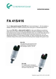
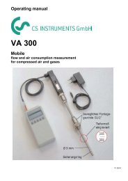
Das <strong>FA</strong> <strong>200</strong>-2<br />
Der Drucktaupunkt tpd ist die Temperatur, bei der die Druckluft gesättigt ist. Das <strong>FA</strong> <strong>200</strong>-<br />
2 liefert ein Ausgangssignal 4...20 mA entsprechend -60...+30 °C tpd für die Weiterverarbeitung.<br />
Das LED-Display zeigt den herrschenden Drucktaupunkt. Über die Tastatur kann<br />
zusätzlich ein Alarm/Grenzwert programmiert und die relative Feuchte eingestellt werden.<br />
Bei Grenzwertüberschreitung schaltet ein Relaiskontakt. Zusätzlich blinkt das Display.<br />
Vorteil:<br />
Überwachung und Alamierung rund um die Uhr.
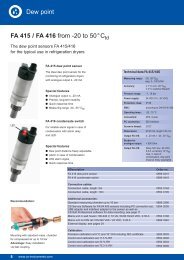
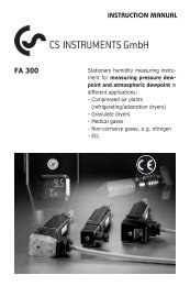
Funktions-<br />
Tasten<br />
197<br />
LED-Anzeige<br />
53<br />
144<br />
12<br />
Stromausgang<br />
4...20 mA<br />
(+) blau (-) schwarz<br />
Spannungsversorgung<br />
24 V DC<br />
57<br />
Abschirmung<br />
53<br />
78<br />
(+) weiss<br />
Geräteabbildung<br />
Geräteabmessungen (in mm)<br />
4<br />
(-) braun<br />
44<br />
Sinterkappe<br />
G 1/2”-Gewinde<br />
Potentialfreier Kontakt<br />
230 V / 1 A<br />
Common: schwarz<br />
NC: braun<br />
NO: blau<br />
PE: gelb/grün<br />
(Belegung siehe Seite 8)<br />
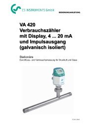
50
Druckluftleitung<br />
Druckluftleitung<br />
Messkammer<br />
Kapillarleitung<br />
Normanschluss<br />
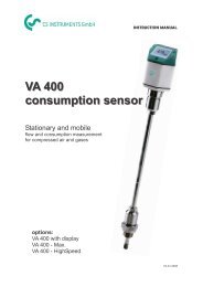
<strong>FA</strong> <strong>200</strong>-2<br />
<strong>FA</strong> <strong>200</strong>-2<br />
5<br />
Installation<br />
Direkt im Druckluftnetz<br />
Fühler mit dem G 1/2”-Gewinde druckdicht mittig oder<br />
oben in die zu messende Druckluftleitung einschrauben.<br />
Darauf achten, dass dicht am Druckluftstrom gemessen<br />
wird. Bei Sackleitungen und nicht strömender Druckluft<br />
ergeben sich sehr lange Reaktionszeiten für den Feuchtemesswert.<br />
Es empfiehlt sich nach Trocknen der Druckluft<br />
und allen Bypassleitungen oder auch bei kritischen<br />
Druckluft-Verbrauchern die Installation durchzuführen.<br />
Indirekt im Druckluftnetz<br />
Fühler mit dem G 1/2”-Gewinde in die Messkammer einschrauben.<br />
Messkammer verbinden mit der Druckluftleitung<br />
über einen Kugelhahn und eventuell eine diffusionsdichte<br />
Anschlussleitung (max. 5 m). Bei öl- und<br />
schmutzhaltiger Druckluft einen Vorfilter 40 µm vor der<br />
Messkammer installieren. Über die Kapillarleitung der<br />
Messkammer strömt kontinuierlich etwas Druckluft ab<br />
(bei 7 bar ca. 1 l/min expandiert). Die Reaktionszeiten<br />
für den Feuchtemesswert sind kürzer als bei der direkten<br />
Montage.
6<br />
Tasten<br />
Einstellungen<br />
Schnellübersicht<br />
Text ↑ ↓ C S Drücken/Sek. Blinken/Hz<br />
1. Messgröße einstellen<br />
Öffnen x 2<br />
1 = °C tpd (Werkseinstellung)<br />
2 = °F tpd<br />
3 = %rF<br />
4 = °Ct<br />
5 = °Ft<br />
Escape x x 2<br />
Speichern x 2<br />
2. Kalibrieren/Abgleich<br />
Kalibrieren x x 2<br />
im Modus<br />
- °C tpd, °F tpd 2 sec. on<br />
- % rF 0,5 sec. off<br />
Escape x x 2<br />
Speichern x 2<br />
3. Alarm einstellen<br />
Einstellung x 2 2 sec. on<br />
Speichern x 2 0,5 sec. off<br />
Alarm 3<br />
Auslesen Anzahl Alarm x 2<br />
Escape x x 2<br />
Speichern (zurück) x 2<br />
4. Skalieren<br />
4mA x x 2 2 sec. on<br />
20 mA x x 2 0,5 sec. off<br />
Escape x x 2<br />
Speichern x 2<br />
5. Werkseinstellung<br />
Werkseinstellung x x x x 2
↑ ↓<br />
C<br />
↑ ↓<br />
C<br />
Falsches Anschließen führt zum Defekt des Sensors.<br />
Der potentialfreie Kontakt ist mit 230 V / 1 A abzusichern.<br />
Bei Inbetriebnahme eine Spannung von 24 V DC anschließen.<br />
Im Display blinkt ca. 4 sec. der mittlere Balken.<br />
Es erscheint der zuletzt gewählte Modus in der<br />
Anzeige.<br />
Vorsichtig Deckel abschrauben.<br />
Wählbare Messgößen sind:<br />
Feuchte<br />
1 °C tpd 2 °F tpd 3 %rF<br />
Umgebungstemperatur<br />
4°Ct 5 °Ft<br />
7<br />
Messen<br />
Elektrischer Anschluss<br />
Gehäuse öffnen<br />
1. Messgröße einstellen<br />
Einstellen aktivieren: Taste ”↓”<br />
Messgröße (1 - 5) auswählen:Taste ”↑” oder Taste”↓”<br />
Auswahl speichern: Taste ”S” 2 sec. drücken.<br />
Auswahl abbrechen: gleichzeitig die Tasten ”↑”<br />
und ”↓” 2 sec. drücken.<br />
S 2. Kalibrieren / Abgleich<br />
(bezieht sich auf die Messgröße im Display)<br />
S<br />
Das <strong>FA</strong> <strong>200</strong>-2 kann vor Ort kalibriert bzw. abgeglichen<br />
werden. Mögliche Einstellungen sind relative Feuchte<br />
oder Taupunkt.<br />
2.1 Anzeige °C tpd oder °F tpd (Drucktaupunkt)<br />
(Abgleich mit Referenzgerät)<br />
Einstellen aktivieren: gleichzeitig Taste ”S” und<br />
Taste ”C” 2 sec. drücken.<br />
Display blinkt.<br />
Messwert einstellen: Taste ”↑” oder Taste”↓”<br />
Auswahl speichern: Taste ”S” 2 sec. drücken.<br />
Auswahl abbrechen: gleichzeitig dieTasten ”↑”<br />
und ”↓” 2 sec. drücken.
au<br />
PE<br />
Schutzleiter<br />
gelb/grün<br />
C<br />
NC<br />
↑ ↓<br />
C<br />
blau<br />
NO<br />
S<br />
C<br />
↑ ↓<br />
S<br />
schwarz<br />
8<br />
Messen<br />
Kalibrieren / Abgleich<br />
2.2 Anzeige %rF (Abgleich mit Kontrollset 11,3 %rF)<br />
Hinweis<br />
- Vor jeder Kalibrierung die Sinterkappe vorsichtig abschrauben.<br />
- Sensor nicht berühren.<br />
- Erschütterungen vermeiden.<br />
- Verschmutzte Sensoren und Sinterkappe mit reinem<br />
Alkohol oder destiliertem Wasser reinigen.<br />
- Sinterkappe von innen nach aussen mit Druckluft ausblasen.<br />
- Kontrolle durchführen nur mit aufgeschraubten Kontroll-/<br />
Abgleichtopf 11,3 %rF (Best.-Nr. 0699.3397).<br />
- Angleichzeit 30 Minuten.<br />
- Temperaturschwankungen und Sonneneinstrahlung vermeiden.<br />
Ist die Abweichung zum Kontrollset >2%, Abgleich durchführen.<br />
Einstellen aktivieren: gleichzeitig Taste ”S” und<br />
Taste ”C” 2 sec. drücken.<br />
Display blinkt 3 x pro sec.<br />
Wert speichern: Taste ”S” 2 sec. drücken.<br />
Auswahl abbrechen: gleichzeitig dieTasten ”↑”<br />
und ”↓” 2 sec. drücken.<br />
3. Alarm einstellen (Überschreiten)<br />
(bezieht sich auf die Messgröße im Display)<br />
Es besteht die Möglichkeit den oberen Grenzwert einzustellen.<br />
Bei Überschreiten des eingestellten Grenzwerts schaltet<br />
das Alarmrelais. Das Display blinkt mit 3 Hz.<br />
Bei Unterschreiten blinkt das Display nicht.<br />
Einstellen aktivieren: Taste ”↑”<br />
Grenzwertert einstellen: Taste ”↑” oder Taste”↓”<br />
Einstellen abbrechen: gleichzeitig dieTasten ”↑”<br />
und ”↓” 2 sec. drücken,<br />
alter Wert bleibt gespeichert.<br />
Grenzwert speichern: Taste ”S” 2 sec. drücken.<br />
Auslesen Anzahl Alarm: Taste ”C” 2 sec. drücken.<br />
Anzahl der Überschreitungen<br />
wird angezeigt.<br />
Zurück ins Messmenü: Taste ”S” 2 sec. drücken.<br />
Speicherinhalt wird auf 0<br />
gesetzt.
↑ ↓<br />
C<br />
S<br />
↑ ↓<br />
C<br />
Standardeinstellung ab Werk (je nach Displayauswahl)<br />
-60...+30 °C tpd = 4...20 mA<br />
-76...+86 °F tpd = 4...20 mA<br />
± 0...100 %rF = 4...20 mA<br />
-20...+50 °C = 4...20 mA<br />
- 4...+122 °F = 4...20 mA<br />
Eingestellte Alarm-Grenzwerte ab Werk:<br />
Messen<br />
4. Skalieren<br />
+30 °C tpd<br />
+86 °F tpd<br />
100 %rF<br />
+50 °C<br />
+122 °F<br />
Vor dem Skalieren Messgröße einstellen (siehe Seite 7)<br />
4 mA<br />
Aktivieren: gleichzeitig Taste ”S” und<br />
Taste ”↓” 2 sec. drücken.<br />
Display blinkt.<br />
Wert einstellen: Taste ”↑” oder Taste”↓”<br />
Speichern: Taste ”S” 2 sec. drücken.<br />
Abbrechen: gleichzeitig dieTasten ”↑”<br />
und ”↓” 2 sec. drücken.<br />
20 mA<br />
Aktivieren: gleichzeitig Taste ”S” und<br />
Taste ”↑” 2 sec. drücken.<br />
Display blinkt.<br />
Wert einstellen: Taste ”↑” oder Taste”↓”<br />
Speichern: Taste ”S” 2 sec. drücken.<br />
Abbrechen: gleichzeitig dieTasten ”↑”<br />
und ”↓” 2 sec. drücken.<br />
5. Werkseinstellung<br />
Aktivieren: gleichzeitig Tasten ”S”,<br />
”C”, ”↑” und ”↓” 2 sec.<br />
drücken.<br />
Das Gerät ist auf Werkseinstellungen<br />
zurückge-<br />
S 9
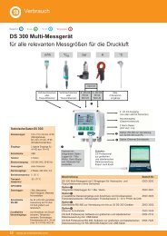
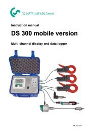
Gramm Wasserdampf je m3 g<br />
feuchtigkeitsgesättigter Druckluft ( ) * 3 m<br />
Luftdruck (bar)<br />
Luftdruck (bar)<br />
Taupunktdiagramm für Druckluft<br />
10<br />
Dieses Diagramm gibt Aufschuss über die<br />
Drucktaupunkt-Veränderung bei Druckverlust.<br />
Als Beispiel ist ein Druckverlust von<br />
8 bar auf 6 bar Betriebsüberdruck dargestellt.<br />
Der Drucktaupunkt wandert in<br />
diesem Fall von 10 °C auf 5 °C ab.<br />
Die Druckreduzierung an<br />
der Entnahmestelle führt<br />
physikalisch bedingt zu<br />
einer Reduzierung des<br />
Drucktaupunkt-Wertes.<br />
Drucktaupunkt °C<br />
* bezogen auf 0 bar, 20 °C
Messbereich: -60...30 °C tpd<br />
0...100 %rF umschaltbar<br />
Druckbereich: -1,0...bis 50 bar<br />
Genauigkeit: ±2 °C tpd<br />
bei -5 °C tpd typisch<br />
Auflösung: 1 °C<br />
Stromvesorgung: 24 VDC, 3.0 VA verwechslungssicher<br />
+10 % und -15 % UN<br />
Stromausgang: 4...20 mA (galvanisch getrennt)<br />
=-60...+30 °Ctd bzw. 0...100 %rF<br />
max. Bürde: < 500 Ω<br />
Anzeige: 3stellig LED-Display<br />
Schutzart: IP 65<br />
Anschluss G 1/2” Einschraubgewinde<br />
(mechanisch): (Edelstahl)<br />
Anschluss Flanschstecker/<br />
(elektrisch): Kupplungsdose M 12 x 1<br />
24 V DC (+) weiss<br />
(-) braun<br />
4...20 mA (+) blau<br />
(-) schwarz<br />
Feuchtigkeit:
Kalibrierung: über 4 interne Tasten in<br />
1°C tpd-Schritte oder bei<br />
11,3%rF<br />
Anzeige: 7 Segment LED<br />
Alarmfunktion: Grenzwerteinstellung über 4 interne<br />
Tasten, LED-Display blinkt<br />
bei Grenzwertüberschreitung<br />
Potentialfreier<br />
Alarmausgang: Wechsler 230 V / 1A belastbar<br />
12<br />
Technische Daten<br />
elektrischer Anschluss<br />
Flanschstecker/<br />
Kupplungsdose M 12 x 1<br />
4 x 0,35 mm 2 Kabel<br />
incl. Schutzleiter<br />
Common: schwarz<br />
NC: braun<br />
NO: blau<br />
PE: gelb/grün<br />
Skalierung Skalierung über 4 interne<br />
Stromausgang: Tasten für 4...20 mA<br />
<strong>FA</strong> <strong>200</strong>-2<br />
Anzeige verschiedener Bedienung über 4 interne Tasten<br />
Werte: 1 °C tpd<br />
2 °F tpd<br />
3 %rF<br />
4 °C t<br />
5 °F t<br />
Auslesen Alarm: die Anzahl aufgetretener<br />
Alarme kann ausgelesen werden
Bestelldaten Artikel-Nr.<br />
<strong>FA</strong> <strong>200</strong>-2, Drucktaupunktmessgerät mit<br />
Display und Grenzwertschalter.......................... 0699.3380<br />
Messkammer mit Standardanschluss ................................0699.3390<br />
Anschlussleitung Länge 5 m, 4polig mit Abschirmung ....0699.3391<br />
Anschlussleitung Länge 10 m, 4polig mit Abschirmung ..0699.3392<br />
Anschlussleitung Alarmkontakt Länge 5 m,<br />
4polig incl. Schutzleiter ......................................0699.3393<br />
Anschlussleitung Alarmkontakt Länge 10 m,<br />
4polig incl. Schutzleiter ......................................0699.3394<br />
Trafo 230 V AC / 24 V DC, 300 mA, mit Anschlussklemmen<br />
im Wandgehäuse IP 65 ......................0699.3395<br />
Präzisionsabgleich bei -40 °C tpd mit Zertifikat ................0699.3396<br />
Kontroll- und Abgleich-Set 11,3 %rF ..............................0699.3397<br />
13<br />
Bestelldaten
Garantie <strong>CS</strong> MESSTECHNIK GmbH Deutschland<br />
Sehr geehrte Kundin,<br />
sehr geehrter Kunde,<br />
vielen Dank für das Vertrauen, das Sie uns mit dem Kauf dieses Messgerätes<br />
entgegengebracht haben. Sie haben eine gute Wahl getroffen. Sollten Sie trotzdem Grund<br />
zur Beanstandung unseres Produktes haben, beheben wir Mängel kostenlos, die<br />
nachweislich auf einen Werksfehler beruhen. Voraussetzung ist, dass Sie diesen Mangel<br />
unverzüglich nach Feststellung und innerhalb der von uns gewährten Garantiezeit melden.<br />
Schäden, die durch nicht bestimmungsgemäßen Gebrauch sowie infolge von Nichtbeachtung<br />
der Bedienungsanleitung entstanden sind, sind von dieser Garantie ausgenommen.<br />
Die Garantie entfällt außerdem, wenn das Messgerät geöffnet wurde - soweit dies nicht<br />
ausdrücklich in der Bedienungsanleitung zu Wartungszwecken beschrieben ist - oder aber<br />
Seriennummern im Gerät verändert, beschädigt oder entfernt wurden.<br />
Die Garantiezeit beträgt für <strong>FA</strong> <strong>200</strong>-2 12 Monate. Wenn nicht anders definiert, gelten für<br />
Zubehörteile 6 Monate. Garantieleistungen bewirken keine Verlängerung der Garantiefrist.<br />
Wurden neben der Garantieleistung notwendige Reparaturen, Justagen oder dergleichen<br />
durchgeführt, sind die Garantieleistungen kostenlos, die anderen Leistungen werden aber<br />
ebenso wie Transport und Verpackung berechnet.<br />
Weitergehende oder andere Ansprüche, insbesondere bei entstandenen Schäden die<br />
nicht das Gerät betreffen sind - soweit eine Haftung nicht zwingend gesetzlich vorgeschrieben<br />
ist - ausgeschlossen.<br />
Leistungen nach der Garantiezeit<br />
Selbstverständlich sind wir auch nach Ablauf der Garantiezeit für Sie da. Bei Funktionsstörungen<br />
senden Sie uns Ihr Messgerät mit einer kurzen Fehlerbeschreibung. Geben Sie<br />
bitte auch Ihre Telefonnummer für eventuelle Rückfragen an.<br />
Bei uns wird KUNDENDIENST groß geschrieben.<br />
14<br />
Garantie
<strong>FA</strong> <strong>200</strong> - 2<br />
Instruction manual<br />
Pressure dew point<br />
measuring instrument<br />
°C C tpd
Contents<br />
Page<br />
Introduction ........................................................................................................................2<br />
Notes on safety ..................................................................................................................3<br />
Description..........................................................................................................................3<br />
Diagram of instrument ........................................................................................................4<br />
Dimensions of instrument ..................................................................................................4<br />
Installation ..........................................................................................................................5<br />
Directly in the compressed air system ......................................................................5<br />
Indirectly in the compressed air system ....................................................................5<br />
Settings ..............................................................................................................................6<br />
Quick overview ..........................................................................................................6<br />
Measuring ..........................................................................................................................7<br />
Electrical connection ..................................................................................................7<br />
Opening the housing ..................................................................................................7<br />
1. Setting the parameter ............................................................................................7<br />
2. Calibrating / Adjusting ............................................................................................7<br />
3. Setting the alarm ....................................................................................................8<br />
4. Scaling....................................................................................................................9<br />
5. Factory setting........................................................................................................9<br />
Dew point diagram for compressed air ............................................................................10<br />
Technical data ..................................................................................................................11<br />
Ordering data....................................................................................................................13<br />
Warranty ..........................................................................................................................14<br />
Testo worldwide ....................................................................................................................<br />
Introduction<br />
You have made the right decision by choosing a measuring instrument from us.<br />
Thousands of customers buy our high standard products every year. There are at least 7<br />
good reasons for doing so:<br />
1) Cost-performance ratio. Reliable quality at a fair price.<br />
2) Extended warranty times of up to 3 years - depending on instrument.<br />
3) We have the ideal solutions for your measuring tasks based on our expert experience<br />
gained over 40 years.<br />
4) Our high quality standard is confirmed by the ISO 9001 certificate.<br />
5) Of course, our instruments carry the CE symbol required by the EU.<br />
6) Calibration certificates for all relevant parameters. Seminars, advice and calibration on<br />
location.<br />
7) Our after-sales service. Ask for more details.<br />
Measuring instrument conforms with EN 50081-2 and EN 50082-2<br />
2
Please read prior to operation<br />
Warning: Mains voltage of 230 V at relay point.<br />
Fuse protection of max. 1 A by the customer if shield is attached.<br />
Do not exceed pressure range of >50 bar.<br />
Observe measuring ranges of sensor!<br />
The probes are damaged if overheated.<br />
Notes on safety<br />
Observe max. storage and transport temperature and<br />
max. operating temperature<br />
(e.g. protect measuring instrument from direct sunlight).<br />
Warranty claims no longer apply if the instrument is opened, in the<br />
case of inexpert handling or use of force.<br />
Adjustments or calibrations should be carried out by qualified<br />
measurement and control engineering staff.<br />
Process stability in compressed air systems<br />
3<br />
Description<br />
Adherence to a specific moisture level (pressure dew point) is required of every<br />
compressed air system to ensure long-lasting uninterrupted operation. The high quality<br />
standards in modern industrial production require non-stop monitoring of moisture with<br />
alarm.<br />
The <strong>FA</strong> <strong>200</strong>-2<br />
Pressure dew point tpd is the temperature at which the compressed air is saturated.<br />
<strong>FA</strong> <strong>200</strong>-2 supplies an output signal of 4 to 20 mA corresponding to -60 to +30 °C tpd for<br />
further processing. The current pressure dew point is shown in the LED display. The keypad<br />
is also used to program the alarm/limit value and to set relative humidity.<br />
A relay point is switched when the limit value is exceeded. The display also flashes.<br />
Advantage:<br />
Round-the-clock monitoring and alarm.
Function<br />
buttons<br />
192<br />
LED display<br />
51<br />
141<br />
12<br />
Power output<br />
4 to 20 mA<br />
(+) blue (-) black<br />
Power supply<br />
24 V DC<br />
57<br />
Cover<br />
52<br />
Diagram of instrument<br />
Dimensions of instrument (in mm)<br />
76<br />
(+) white<br />
4<br />
(-) brown<br />
44<br />
Floating contact<br />
230 V / 1 A<br />
Sintered cap<br />
G 1/2” thread<br />
Common: black<br />
NC: brown<br />
NO: blue<br />
PE: yellow/green<br />
(See page 8 for<br />
assignment)<br />
50
Compressed air pipe<br />
Compressed<br />
air pipe<br />
Capillary<br />
pipe<br />
Standard<br />
connection<br />
<strong>FA</strong> <strong>200</strong>-2<br />
<strong>FA</strong> <strong>200</strong>-2<br />
Measuring<br />
chamber<br />
5<br />
Installation<br />
Directly in the compressed air system<br />
Screw in probe with G 1/2 thread pressure-tight in the<br />
centre or in the compressed air pipe where the<br />
measurement is to take place.<br />
Ensure that the measurement is carried out close to the<br />
compressed air flow. U-bend pipes or non-flowing<br />
compressed air result in very slow reaction times for the<br />
moisture reading. Installation is recommended following<br />
drying of the compressed air and all bypass pipes or for<br />
critical compressed air users.<br />
Indirectly in the compressed air system<br />
Screw in probe with the G 1/2” thread in the measuring<br />
chamber. Connect measuring chamber with the<br />
compressed air pipe using a ball valve and possibly a<br />
diffusion-tight connection pipe (max. 5m). In the case of<br />
compressed air containing oil and dirt particles, a 40 µm<br />
pre-filter should be installed in front of the measuring<br />
chamber. Compressed air flows continuously<br />
(at 7 bar, approx. 1 l/min. expanded) in the capillary pipe<br />
of the measuring chamber. The reaction times for the<br />
humidity reading are shorter than when directly mounted.
6<br />
Buttons<br />
Settings<br />
Quick overview<br />
Text ↑ ↓ C S Press/sec. Flash/Hz<br />
1. Setting the parameter<br />
Open x 2<br />
1 = °C tpd (Factory setting)<br />
2 = °F tpd<br />
3 = %RH<br />
4 = °Ct<br />
5 = °Ft<br />
Escape x x 2<br />
Save x 2<br />
2. Calibrating/Adjusting<br />
Calibration x x 2<br />
in mode<br />
- °C tpd, °F tpd 2 sec. on<br />
- % RH 0.5 sec. off<br />
Escape x x 2<br />
Save x 2<br />
3. Setting the alarm<br />
Setting x 2 2 sec. on<br />
Save x 2 0.5 sec. off<br />
Alarm 3<br />
Read out Number Alarm x 2<br />
Escape x x 2<br />
Save (restore) x 2<br />
4. Scaling<br />
4mA x x 2 2 sec. on<br />
20 mA x x 2 0.5 sec. off<br />
Escape x x 2<br />
Save x 2<br />
5. Factory setting<br />
Factory setting x x x x 2
↑ ↓<br />
C<br />
↑ ↓<br />
C<br />
Incorrect connection cause defects in the sensor.<br />
The floating contact is protected with 230 V / 1 A.<br />
Connect power of 24 V DC for initial operation. The<br />
middle bar flashes for approx. 4 sec. in the display. The<br />
mode last selected is shown.<br />
Unscrew the cover carefully.<br />
7<br />
Electrical connection<br />
Opening the housing<br />
1. Setting the parameter<br />
The following parameters can be selected:<br />
Moisture<br />
1 °C tpd 2 °F tpd 3 %RH<br />
Ambient temperature<br />
4°Ct 5 °Ft<br />
Measuring<br />
Activate setting: “↓” button<br />
Select parameter (1 - 5): “↑” button or “↓” button<br />
Save selection: Press “S” for 2 sec.<br />
Cancel selection: Press the “↑” and “↓” buttons<br />
simultaneously for 2 sec.<br />
S 2. Calibrating / Adjusting<br />
(refers to the parameter in the display)<br />
S<br />
<strong>FA</strong> <strong>200</strong>-2 can be calibrated or adjusted on location.<br />
Relative humidity or dew point are possible settings.<br />
2.1 Display: °C tpd or °F tpd (pressure dew point)<br />
(Adjust using reference instrument)<br />
Activate setting: Press “S” and “C” buttons<br />
simultaneously for 2 sec.<br />
Display flashes.<br />
Set reading: “↑” button or “↓” button<br />
Save selection: Press “S” for 2 sec.<br />
Cancel selection: Press the “↑” and “↓” buttons<br />
simultaneously for 2 sec.
C<br />
brown<br />
PE<br />
Protective<br />
conductor<br />
yellow/green<br />
↑ ↓<br />
C<br />
S<br />
blue<br />
NC<br />
NO<br />
C<br />
↑ ↓<br />
S<br />
black<br />
8<br />
Measuring<br />
Calibrating / Adjusting<br />
2.2 Display: %RH (adjustment with 11.3 %RH control set)<br />
Note<br />
- Carefully remove the sintered cap prior to every<br />
calibration<br />
- Do not touch sensor.<br />
- Avoid vibrations.<br />
- Clean dirty sensors and sintered cap with pure alcohol<br />
or destilled water.<br />
- Flush sintered cap from the inside to the outside with<br />
compressed air.<br />
- Check should only be carried out using screwed-on<br />
11.3%RH control/adjustment container<br />
(Part no. 0699.3397).<br />
- Adaptation time: 30 minutes.<br />
- Avoid fluctuations in temperature and sunlight.<br />
If the deviation from the control set >2% adjustment must<br />
be carried out.<br />
Activate setting: Press “S” and “C” buttons<br />
simultaneously for 2 sec.<br />
Display flashes with 3 x per<br />
sec.<br />
Save value: Press “S” for 2 sec.<br />
Cancel selection: Press “↑” and “↓” buttons<br />
3. Setting the alarm (exceeding)<br />
(refers to the parameter in the display)<br />
It is possible to set the top limit value.<br />
The alarm relay switches when the set limit value is<br />
exceeded. The display flashes with 3 Hz.<br />
The display does not flash if the value undercuts the limit.<br />
Activate setting: “↑” button<br />
Set limit value: “↑” button or “↓” button<br />
Cancel setting: Press the “↑” and ”↓” buttons<br />
simultaneously for 2 sec.,<br />
old value remains saved.<br />
Save limit value: Press “S” for 2 sec.<br />
Read out Quantity Alarm: Press “C” for 2 sec.<br />
Number of times exceeded<br />
is displayed.<br />
Return to measurement Press “S” for 2 sec.<br />
menu Memory contents are set<br />
at 0.
↑ ↓<br />
C<br />
S<br />
↑ ↓<br />
C<br />
Standard factory setting (depending on display selection)<br />
-60 to +30 °C tpd = 4 to 20 mA<br />
-76 to +86 °F tpd = 4 to 20 mA<br />
± 0 to 100 %RH = 4 to 20 mA<br />
-20 to + 50 °C = 4 to 20 mA<br />
- 4 to +122 °F = 4 to 20 mA<br />
Alarm limit values set in factory:<br />
+30 °C tpd<br />
+86 °F tpd<br />
100 %RH<br />
+50 °C<br />
+122 °F<br />
Set parameter before scaling (see page 7)<br />
Measuring<br />
4. Scaling<br />
Activate 4 mA: Press “S” and “↓” buttons<br />
simultaneously for 2 sec.<br />
Display flashes.<br />
Set value: “↑” button or “↓” button<br />
Save: Press “S” for 2 sec.<br />
Cancel: Press the “↑” and “↓” buttons<br />
simultaneously for 2 sec.<br />
Activate 20 mA: Press “S” and “↑” buttons<br />
simultaneously for 2 sec.<br />
Display flashes.<br />
Set value: “↑” button or “↓” button<br />
Save: Press “S” button for 2 sec.<br />
Cancel: Press “↑” and “↓” buttons<br />
simultaneously for 2 sec.<br />
5. Factory setting<br />
Activate: Press “S”, “C”, “↑” and “↓”<br />
buttons simultaneously for<br />
2 sec.<br />
The instrument is reset to<br />
the factory settings.<br />
S 9
Gramme of water vapour per m3 g<br />
of moisture saturated compressed air ( ) * 3 m<br />
Air pressure (bar)<br />
Air pressure (bar)<br />
Dew point diagram for compressed air<br />
10<br />
The diagram provides information on the<br />
change in pressure dew point when there<br />
is a drop in pressure. Example: a drop in<br />
pressure from 8 bar to 6 bar working<br />
positive pressure is shown. In this case<br />
the pressure dew point drops from 10 °C<br />
to 5 °C.<br />
A reduction in pressure<br />
at the sampling point<br />
may result in a reduction<br />
of the pressure dew<br />
point value.<br />
Pressure dew point °C<br />
* with reference to 0 bar, 20 °C
Measuring range: -60 to 30 °C tpd<br />
0 to 100 %RH, switchable<br />
Pressure range: -1.0 to 50 bar<br />
Accuracy: ±2 °C tpd<br />
at -5 °C tpd typically<br />
Resolution: 1 °C<br />
Power supply: 24 VDC, 3.0 VA, cannot be<br />
confused, +10 % and -15 % UN<br />
Power output: 4 to 20 mA (electrically isolated)<br />
=-60 to +30 °Ctd or 0 to 100 %RH<br />
Max. load < 500 Ω<br />
Display: 3 digit LED display<br />
Protection class: IP 65<br />
Connection G 1/2” screw-in thread<br />
(mechanical): (stainless steel)<br />
Connection Flange plug/<br />
(electrical): coupling socket M 12 x 1<br />
24 V DC (+) white<br />
(-) brown<br />
4 to 20 mA (+) blue<br />
(-) black<br />
Moisture:
Calibration: Via 4 internal buttons in<br />
1°C tpd steps or at<br />
11.3%RH<br />
Display: 7 segment LED<br />
Alarm function: Limit value setting via 4 internal<br />
buttons, LED display flashes<br />
when limit value is exceeded<br />
Floating<br />
alarm output: Change-over contact, can take<br />
230 V / 1A<br />
12<br />
Technical data<br />
Electrical connection<br />
flange plug/<br />
coupling socket M 12 x 1<br />
4 x 0.35 mm 2 cable<br />
incl. protective conductor<br />
Common: black<br />
NC: brown<br />
NO: blue<br />
PE: yellow/green<br />
Scaling Scaling via 4 internal<br />
power output: buttons for 4 to 20 mA<br />
<strong>FA</strong> <strong>200</strong>-2<br />
Display of different Operation via 4 internal buttons<br />
values: 1 °C tpd<br />
2 °F tpd<br />
3 %RH<br />
4 °C t<br />
5 °F t<br />
Read off alarm: The number of activated alarms<br />
can be read off.
Ordering data Item no.<br />
<strong>FA</strong> <strong>200</strong>-2, pressure dew point measuring instrument with<br />
display and limit value switch ............................ 0699.3380<br />
Measuring chamber with standard connection ................0699.3390<br />
Connection cable 5 m long, 4 pin with cover....................0699.3391<br />
Connection cable 10 m long, 4 pin with cover..................0699.3392<br />
Connection cable alarm contact, 5 m long,<br />
4 pin with protective conductor ..........................0699.3393<br />
Connection cable alarm contact, 10 m long,<br />
4 pin with protective conductor ..........................0699.3394<br />
Transfo 230 V AC / 24 V DC, 300 mA, with connection<br />
terminals in a IP 65 wall housing........................0699.3395<br />
Precision calibration at -40 °C tpd with certificate ............0699.3396<br />
Control and adjustment set 11.3 %RH ............................0699.3397<br />
13<br />
Ordering data
Dear Customer<br />
Thank you for your confidence in <strong>CS</strong> MESSTECHNIK which you have shown by buying<br />
this measuring instrument. You have made the right choice by choosing a quality product.<br />
If you have reason for complaint we will repair any faults free of charge if it can be proven<br />
that they are manufacturing faults. The fault should be reported immediately after it has<br />
been found and within the warranty time guaranteed by us.<br />
Not included in the warranty is damage caused by improper use and non-adherence to<br />
the instruction manual.<br />
The warranty is also cancelled once the measuring instrument has been opened provided<br />
this is not described in the instruction manual for maintenance purposes.<br />
The warranty time is 1 year for the <strong>FA</strong> <strong>200</strong>-2, and 6 months for accessories, if not<br />
otherwise stated. Warranty services do not extend the warranty time.<br />
If in addition to the warranty service necessary repairs, adjustments or similar are carried<br />
out, the warranty services are free of charge but there is a charge for the other services<br />
in addition to the transport and packaging costs.<br />
Other claims, especially those for damage occurring outside the instrument are not<br />
included unless responsibility is legally binding.<br />
After-sales service after the warranty time has elapsed<br />
We are, of course, there for you after the warranty time has elapsed. In the case of<br />
function faults please send us your measuring instrument with a brief description of the<br />
defect. Include your telephone number should we need to contact you.<br />
CUSTOMER SERVICE puts the customer first.<br />
<strong>CS</strong> MESSTECHNIK GmbH<br />
Am Oxer 28c<br />
D-24955 Harrislee/Germany<br />
Tel. +49(0)461 - 700 20 25<br />
Fax +49(0)461 - 700 20 26<br />
E-mail: cs@dewpoint.de<br />
WEB: www.dewpoint.de<br />
14<br />
Warranty