
Create successful ePaper yourself
Turn your PDF publications into a flip-book with our unique Google optimized e-Paper software.
Model 3455A<br />
1-2, This Operating and &Senrice Manual contains informa-<br />
tion necessary to install, operate, test. adjust, and service<br />
the Hewlett-Paekard Model 3455A Digital Voltmeter.<br />
1-3. Included with this manual is an Operating information<br />
supplement. The supplement is a duplication of the first<br />
three sections of this manual and should be kept with the<br />
instrument for use by the operator.<br />
14. This section of the manual contains the performance<br />
specifications and general operating characteristics of the<br />
3455~, Also listed aw available options and accessories,<br />
and instrument and manual identification infonation.<br />
1.8. Instrument identification by serial number i s Iocated<br />
on the rear panel. Hewlett-Packard uses r two-section serial<br />
number consisting of a four-digit prefix and a fivedigit<br />
suffm separated by a letter designating the country in<br />
which the instrument was manufactured. (A = U.S.A.;<br />
G = West Germany; J = Japan; U = United Kingdom.) The<br />
prefuc is the same for all identical instruments and changes<br />
onIy when a major instrument change is made. The suffix,<br />
however, is assigned sequentidly and is unique to each<br />
instrument.<br />
1-9. This manual applies to instruments with serial num-<br />
bers indicated an the title page. If changes have been made<br />
in the instrument since this manual was printed, a yellow<br />
"Manual Changes" supplement supplied with the manual<br />
will define these changes and explain how to adapt the<br />
manual to the newer instruments. In addition, backdating<br />
information contained in Section V11 adapts the manual to<br />
instruments with serial numbers lower than those listed on<br />
the title page.<br />
1-10. hrt numbers for the manual and the microfiche<br />
copy of the manual arc also listed on the title page.<br />
1.1 1. D ESCR lPTlO l.<br />
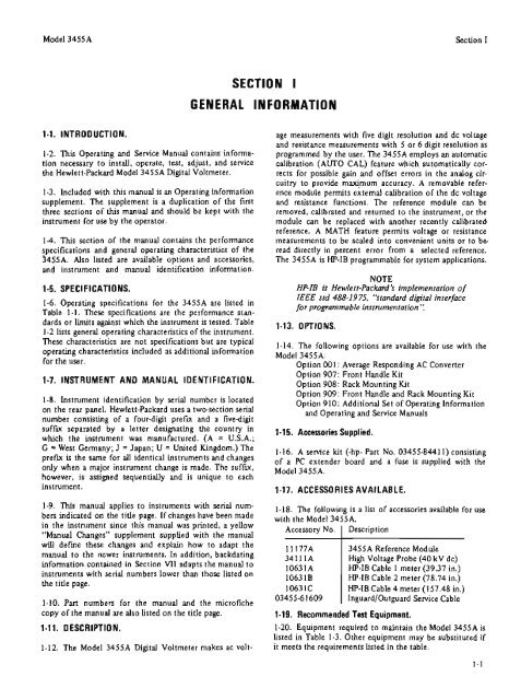
1-12. The Model 3455A Digital Voltmeter makes ac volt-<br />
SECTION I<br />
Section I<br />
age measurements with five digit resolution and dc voltage<br />
and resistance measurements with 5 or 6 digit resolution as<br />
programmed by the user. The 3455A employs an automatic<br />
calibration (AUTO CALI feature which automatically cor-<br />
rects for possible gain and offset erron in the andog cir-<br />
cuitry to provide maximum accuracy. A remavable refer-<br />
ence module permits external calibration of the dc voltage<br />
and resistance functions. The reference module can be<br />
removed, calibrated and returned to the instrument, or the<br />
module can be replaced with another recently calibrated.<br />
reference. A MATH feature permits voItage or resistance<br />
measurements to be scaled into convenient units or to be<br />
read directly in percent enor from a selected recerence.<br />
The 3455A is HPdB proflmrnabIe for system applications.<br />
HP-=IB is Havlett-Pockoml 's implementation of<br />
1-5. SPE CI F I CATIO 'NS.<br />
IEEE std 488- 19 75, "'srond(~rd digitaI interface<br />
Id. Operating specifications for the 3455A are listed in for pmgrammobIe imfmmentation ':<br />
Tabk 1-1. These specifications are the performance standards<br />
or limits again. which the inarumcnt is tested. Table 1-13. O ~ ~ O N S<br />
1-2 lists general operating characteristics of the instrument.<br />
These characteristics are not specifications but are typical The options are available u+ with the<br />
operating characteristics included as additional information<br />
Model 3455A3<br />
for the user. Option 00 1: Average Responding AC Converter<br />
Option 907: Front Handle Kit<br />
1.7, IISTRUMENT AND MANUAL IDENTIFICATION. Option 908: Rack Mounting Kit<br />
Option 909: Front Handle and Rack Mounting Kit<br />
Option 9 10: Additional Set of Operating Information<br />
and Operating and Service Manuals<br />
1 - t 5. Accsasorias Supplied.<br />
1-16. A senice kit (-hp- Part No. 03455-8441 1) consisting<br />
of a PC extender board and a fuse is supplied with the<br />
Model J455A.<br />
1-17. ACCESSORIES AVAILABLE.<br />
1- 18. The following is a list of accessories available for use<br />
with the Model 3455A<br />
Accessory No. 1 Description<br />
-<br />
I1 177A<br />
3411tA<br />
I063 1 A<br />
106318<br />
I063IC<br />
03455-6 1609<br />
3455A Reference Module<br />
High Voltage Probe (40 kV dc)<br />
HP-IB Cable 1 meter 139.37 in.)<br />
IP-IB Cable 2 meter (78.74 in.)<br />
HP-IB Cable 4 meter (1 57.48 in.)<br />
Inguatd/Outguard Service Cable<br />
1-19. Recommended Test Equipmsmt.<br />
1-20. Equipment required to maintain the Model 345SA is<br />
listed in Table 1-3. Other equipment may be substituted if<br />
it meets the requirements listed in the table.