
Create successful ePaper yourself
Turn your PDF publications into a flip-book with our unique Google optimized e-Paper software.
Model 3455A Section III<br />
3-2. This section contains infomation and instructions<br />
necessary for operation of the Modtl 3455A Digital<br />
Voltmeter. Included is a description of operation<br />
characteristics, a description of the operating controls<br />
and indicators, and functional checks to be performed<br />
by the operator.<br />
3-3. OPEflATkllG CHARACTERISTICS.<br />
3-5. Befare connecting ac power to the 345519, make<br />
certain the rear panel lint selector switches are set to<br />
correspond to the voltage and frequency of the available<br />
power line and that the proper fuse is installed for the<br />
voltage selected. For rated measurement accuracy, the<br />
3455A should be aIlowed to warm up for at least one<br />
hour.<br />
SECTION Ill<br />
OPERATING INSTRUCTIONS<br />
logic of the instrument. When all these measurements<br />
and caSculations are compIeted. the 34S5A wilI display<br />
+ .8.8.8.8.8.8.8. and the self-test operation will start<br />
again. In order to bring the instrument out of this mode,<br />
any other function button must be pressed.<br />
3-8. En the event of a cal constant failure, the Self-Test<br />
operation will stop and the failing cal constant's number<br />
will be displayed (an integer number from 13 to 0). If<br />
the dummy calculation fails, a non integer number is<br />
displayed {e.g., 9.998 or 10.Mi2 etc.).<br />
3-9. The Self-Test function can be remotely programm-<br />
ed, as described in the programming portion of this sec-<br />
tion. The 3455A will output a 10 upon a succtssful com-<br />
pletion of the tat and if addressed to "talk." If the<br />
dummy calculation fails, the answer of the dummy<br />
calc~llation will be the output (9.998 or 10.002 etc.). If<br />
any auto-cal constants fail, the 3455A will not output<br />
any readings, (times out).<br />
3.6. s8R Tmt Opantlon. NOTE<br />
3-7. Thc internal test function of the 3455A verifies the The seCf test fmm does not test opemrion<br />
operation of the dc analog circuitry, inguard and of the ohms or ac sections nor the measure-<br />
outguard logic circuitry, and the front panel indicators ment amuracy of the 3455A.<br />
and display. The primary test of the dc analog circuitry<br />
is the measurement of various Auto-Cal constants. A 3-10, QC Yohqs Ma~rmtmt<br />
logic check is also performed, when all the cal constant<br />
measurements are taken. The logic check consists of a 3-1 1. The Model W55A measures dc voltagc from 1<br />
dummy cal constant calculation made in the outguard microvolt to 1OOO volts in five ranges extending from .1<br />
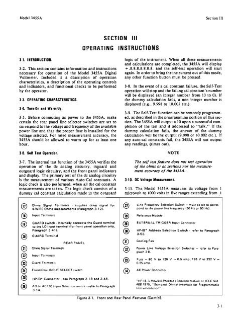
Ohms Slgnnl Terminals - supplims drhra signal fw<br />
4-WIRE Ohms measurements (Paragraph 3-1 21.<br />
Input Terminals<br />
GUAAO switch - Internally connects the Guard terminal<br />
to the LO Input terminal Ifor front panel opemtion only,<br />
Paragraph 3-41 1.<br />
GUARD Terminal<br />
Ohms Signal Terminals<br />
Input Terminals<br />
Guard Terminals<br />
REAR PANEL<br />
FrontlRear INPUT SELECT switch<br />
HP-IS" Connector - see Paragraph 2-1 8 and 3-48<br />
AC or AClOC Input Select~on sw~tch - refw to Paragraph<br />
5-14.<br />
Cine Frequency Selection Switch - must be set to cones<br />
pond to The power line frequency 450 Hz or 60 Hz).<br />
Reference Module<br />
EXTERNAL TRIGGER Input Connacror<br />
HP-IS" Address Sa!mtion Switch - mkr to Paragraph<br />
3-53.<br />
Cooling Fan<br />
Power Line Voltage Selection Switches - refer to Para-<br />
graph 2-8.<br />
Fuse - 90 W to 126 V - 0.5 amp. 198 V to 252 V -<br />
0.25 amp.<br />
AC Power Connector.<br />
Figure 3-1. Front and Rear Panel Features (Cont'd).<br />
"HP-1B IS Hewlett-Packard's implementation of IEEE Srd.<br />
488-1975. "Standard D~gital Interface for Programmable<br />
InstrumenTation".