
You also want an ePaper? Increase the reach of your titles
YUMPU automatically turns print PDFs into web optimized ePapers that Google loves.
Model 3455A<br />
voltage and vmier controls for a zero reading on the<br />
null meter.<br />
r. Downrange the Null Meter and adjust the<br />
Reference Divider's course and fine controls for a null is<br />
obtained on the 3 rnicrovoIt range.<br />
s. Set the Reference Divider's Standard Cell switch to<br />
Open. Allow ten minutes for the Reference Divider to<br />
warm-up and stablize.<br />
t. Set the Reference Divider's Standard Cell switch to<br />
Momentary and, if necessary, readjust the fine control<br />
for a nu11 indication. Release the Standard Cell switch.<br />
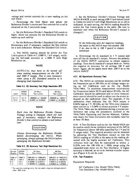
u. The 3455A reading should be within the Test<br />
Limits given in Table 4-3. (1000 V, I kV range), verifying<br />
the full-scale accuracy at + 1 0 V with High<br />
Resolution on.<br />
AUTO-CAL may have to be turned off<br />
when making measurements on the 100 Y<br />
and 2000 V mges. This is only necessary<br />
when using o DC Standard sensirive lo a<br />
changing load impdunce.<br />
Table 4-2, DC Accuracy TW (High Wmalation OW.<br />
3455A 24 Hour 90 Day<br />
Test Limits Test Limits<br />
10 V a 9.9997 to 10.0003 9.9994 to 10.0QO6<br />
NOTE<br />
Each lime the Reference Divider Output<br />
Votrage setting is changed, check for null<br />
and, if necessary, readjust the Reference<br />
Divider's fine control to obtain a null indica-<br />
tion.<br />
Always downrange the Reference Divider<br />
befoe downranging the 3455A. When<br />
upranging, always upran;ge the 3455A before<br />
upranging the Reference Divider.<br />
24 Hour<br />
'For positive readings only. Do not apply negative voltages greater<br />
than - 500 V dc.<br />
Section IV<br />
v. Set the Reference Divider's Output Voltage and<br />
3455A RANGE to each setting (100 V and below) listed<br />
in Tables 4-2 and 4-3 with High Resolution on or off as<br />
indicated. Aa each setting, the 345SA reading should be<br />
within the Test Limits given in the table. (Be sure to<br />
maintain null when the Reference Divider" output is<br />
changed.)<br />
In the fdawing tests for negative readings,<br />
the inpur lo the 3455A mrrsf nor exceed -500<br />
V dc, due to the k 500 V guard f o chassis<br />
limitation,<br />
w. Downrange the dc standard to 1 Y output and<br />
turn off the dc standard's output. Reverse the polarity<br />
of the 3455A INPUT connection to obtain negative<br />
readings. Turn the dc standard's output back on. Verify<br />
the negative dc accuracy for all settings 100 V and<br />
lower. Again, do not apply more than -500 Y dc to he<br />
3455A INPUT.<br />
4-32. The 3455A ac voltmeter accuracy can be verified<br />
for frequencies up to 100 kHz on a11 voltage ranges us-<br />
ing an AC Calibrator such as the -hp- Model<br />
745A/746A. To minimize measurement uncertainties<br />
for frequencies below 50 Hz and above 20 kHz, the AC<br />
Calibrator should be calibrated and its error measure-<br />
ment control should be used to adjust out the errors in-<br />
dicated on the calibration chart. For example, if the<br />
calibration chan indicates that the 74% output is<br />
0.04% high at 1 V, 50 kHz, set the 745A error measure-<br />
ment control to + 0.04% to obtain a precise 1 V output.<br />
The 745A/746A can be calibrated during a routine pw-<br />
forrnance test using the procedures outlined in the<br />
745A/746A Operating and Service Manuals. Calibra-<br />
tion charts for these instruments are normally valid for<br />
at least 30 days.<br />
4-33. A Test Oscillator such as the -hp Model 652A can<br />
be used to verify the ac voltmeter accuracy of the 3455A<br />
for frequencies above 100 kHz (specified for 1 V and 10<br />
V ranges only). The required accuracy can be obtained<br />
by adjusting the Test Oscillator output so that the<br />
3455A reading at I0 kHz is the same as the reading ob-<br />
tained with the highly accurate AC Calibrator. This<br />
reference level can then be maintained to within 2<br />
0.25% over the 100 kHz to 1 MHz range using the<br />
expanded-scale meter on the Test Oscillator. If higher<br />
accuracy is desired, an ac-to-dc thermal triinsfer techni-<br />
que (Figure 4-3) can be used.<br />
4-34. Twt Proeedun.<br />
Equipment Required:<br />
AC Calibrator (-hp- Mode! 745A/746A)<br />
Test Oscillator (-hp Model 65ZA)