
Create successful ePaper yourself
Turn your PDF publications into a flip-book with our unique Google optimized e-Paper software.
a. nm LDC*~CTW*I-~ E ~ H E C m ~ uu*r ~ -.<br />
m,,,<br />
B W-0 CDI*CTtD fl) LW A1 WLIYLICI.<br />
s ---<br />
C WhRU CDIlFOm 10 E M H -0.<br />
rl(lLr1w<br />
m c m r a<br />
6WeW11<br />
W -7-<br />
W CWw*r W E IRW<br />
tws r-mww IIb<br />
QlYDIIQAI<br />
wt -7501<br />
(PwDDtflllCM<br />
LOU rmenrr r,.<br />
c*uqrm r m<br />
-<br />
axe RZrkm aun<br />
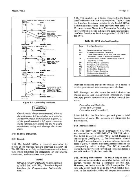
Figure 3-3. Connecting the Guard,<br />
Guard should olw~ys be connecfed. either to<br />
the inslrumen! LO rerminaf or lo a point in<br />
the source circuit as indicated in Figure 3-3.<br />
If the guard ~erminai is left open, commonmode<br />
voltages may exceed the LO-to-Guard<br />
breakdown rating ond damog~ the insirumen!.<br />
5-40. REMOTE OPERATION.<br />
3-50. The Model 3455A is remotely controlled by<br />
means of the Hewlett-Packard Interface Bus (HP-10).<br />
The HP-IB is a carefully defined instrumentation inter-<br />
face which simplifies the integration of instruments,<br />
calc~lators, and computers into systems.<br />
NOTE<br />
HP-IB is Hewlen-Pockord's implementution<br />
of IEEE Sfd. 488-1975, "Sundurd Digital<br />
Interface Jar Progranrmoble Insrrumenra-<br />
lion. "<br />
Section 111<br />
3-51. The capability of a device connected to the Bus is<br />
specified by the interface functions it has. Table 3-2 Iists<br />
the Interface Functions included in the Model 3455k.<br />
These functions are also listed above the rear panel MB-<br />
IB connector (see Figure 3- 1). The number following the<br />
interface function code indicates the particular capabili-<br />
ty of that function as listed in Appendix C of IEEE Std.<br />
488-1975.<br />
Code<br />
SHI<br />
AH?<br />
T5<br />
L4<br />
SR1<br />
R LI<br />
PPO<br />
DC1<br />
DT1<br />
C@<br />
El<br />
Table 3-2. AP-I0 Intarflee Capability.<br />
Interface Functron<br />
Source Handshake mpab1111y<br />
Acceptor Handshake Capabltity<br />
Talker {bas~c talker. serral poll. talk onfy mode.<br />
wnaddress to talk !f addressed to listen)<br />
Lrstener (bas~c Irstener. unaddress to l~sten ~f<br />
addressed to rslkl<br />
Servtce Request Capabilrty<br />
RemotelLocal Capab~l~ty<br />
No Parallcl Poll Capabrl~ty<br />
Device Clear Capab~lrty<br />
Qevlee Trlgger Capabrllty<br />
No Controller Capability<br />
Open Collector lBus Drivers<br />
Interface Functions provide the means for a dwice to<br />
receive, process and send messages over the bus.<br />
3-52. Messages are the means by which devices ex-<br />
change control and measurement information. These<br />
messages permit communication and/or control bet-<br />
ween:<br />
Controller and Device(s)<br />
Device and Device(s)<br />
Controller and Controller(s)<br />
Table 3-3 lists the Bus Messages and gives a brief<br />
description of each. The messages are categorized by<br />
Bus function.<br />
3.53. Address Sslection.<br />
3-54. The '"talk" and "listen" addresses of the 3455A<br />
are seIected by the INSTRUMENT ADDRESS switch.<br />
This switch is a seven section "Dip" switch located on<br />
the rear panel (see Figure 3- 1). The Five switches, labeled<br />
I through 5 are used to select a unique talk and listen ad-<br />
dress. Figure 3-4 lists the available address codes and the<br />
corresponding switch settings. The 3455A normally<br />
leaves the factory with the switch set to listen address 6<br />
and talk address V (decimal code 44).<br />
3-55, Talk Only IHo Cotrtrallsf). Tbe 3455A may be used to<br />
provide measurement data to another device, such as a<br />
printer, without having a controller on the Bus.<br />
However, the device must be HP-I8 compatible. The<br />
talk only switch must be set to the TALK ONLY posi-<br />
tion. In this mode the 3455A will output measurement<br />
1