A Text Book on Engineering Graphics - Central Board of Secondary ...
A Text Book on Engineering Graphics - Central Board of Secondary ...
A Text Book on Engineering Graphics - Central Board of Secondary ...

Create successful ePaper yourself
Turn your PDF publications into a flip-book with our unique Google optimized e-Paper software.
A<br />
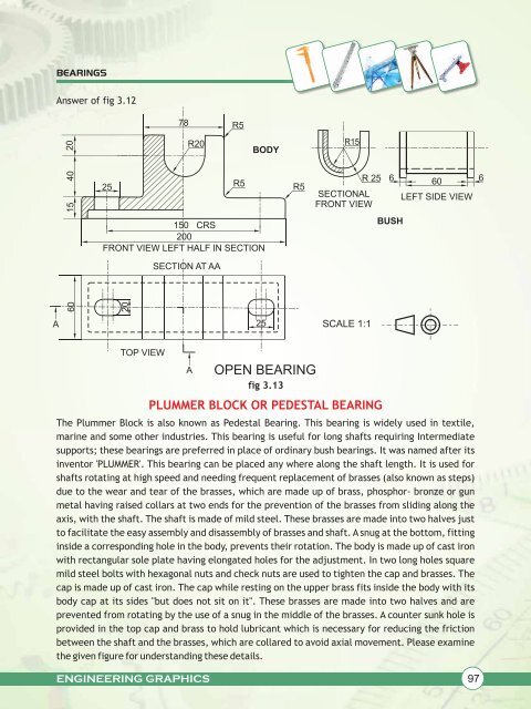
BEARINGS<br />
Answer <strong>of</strong> fig 3.12<br />
20<br />
40<br />
15<br />
60<br />
25<br />
78<br />
R20<br />
ENGINEERING GRAPHICS<br />
R5<br />
BODY<br />
150 CRS<br />
200<br />
FRONT VIEW LEFT HALF IN SECTION<br />
20<br />
TOP VIEW<br />
SECTION AT AA<br />
A<br />
R5 R5<br />
25<br />
OPEN BEARING<br />
fig 3.13<br />
PLUMMER BLOCK OR PEDESTAL BEARING<br />
6 60 6<br />
LEFT SIDE VIEW<br />
The Plummer Block is also known as Pedestal Bearing. This bearing is widely used in textile,<br />
marine and some other industries. This bearing is useful for l<strong>on</strong>g shafts requiring Intermediate<br />
supports; these bearings are preferred in place <strong>of</strong> ordinary bush bearings. It was named after its<br />
inventor 'PLUMMER'. This bearing can be placed any where al<strong>on</strong>g the shaft length. It is used for<br />
shafts rotating at high speed and needing frequent replacement <strong>of</strong> brasses (also known as steps)<br />
due to the wear and tear <strong>of</strong> the brasses, which are made up <strong>of</strong> brass, phosphor- br<strong>on</strong>ze or gun<br />
metal having raised collars at two ends for the preventi<strong>on</strong> <strong>of</strong> the brasses from sliding al<strong>on</strong>g the<br />
axis, with the shaft. The shaft is made <strong>of</strong> mild steel. These brasses are made into two halves just<br />
to facilitate the easy assembly and disassembly <strong>of</strong> brasses and shaft. A snug at the bottom, fitting<br />
inside a corresp<strong>on</strong>ding hole in the body, prevents their rotati<strong>on</strong>. The body is made up <strong>of</strong> cast ir<strong>on</strong><br />
with rectangular sole plate having el<strong>on</strong>gated holes for the adjustment. In two l<strong>on</strong>g holes square<br />
mild steel bolts with hexag<strong>on</strong>al nuts and check nuts are used to tighten the cap and brasses. The<br />
cap is made up <strong>of</strong> cast ir<strong>on</strong>. The cap while resting <strong>on</strong> the upper brass fits inside the body with its<br />
body cap at its sides "but does not sit <strong>on</strong> it". These brasses are made into two halves and are<br />
prevented from rotating by the use <strong>of</strong> a snug in the middle <strong>of</strong> the brasses. A counter sunk hole is<br />
provided in the top cap and brass to hold lubricant which is necessary for reducing the fricti<strong>on</strong><br />
between the shaft and the brasses, which are collared to avoid axial movement. Please examine<br />
the given figure for understanding these details.<br />
R15<br />
R 25<br />
SECTIONAL<br />
FRONT VIEW<br />
SCALE 1:1<br />
BUSH<br />
97