- Page 1 and 2: A Text Boo
- Page 3 and 4: Foreword Design is an integral aspe
- Page 5: PREAMBLE THE CONSTITUTION OF INDIA
- Page 9 and 10: CHAPTER 1 1.1 INTRODUCTION The obje
- Page 11 and 12: ISOMETRIC PROJECTION 1.2.2 POSITION
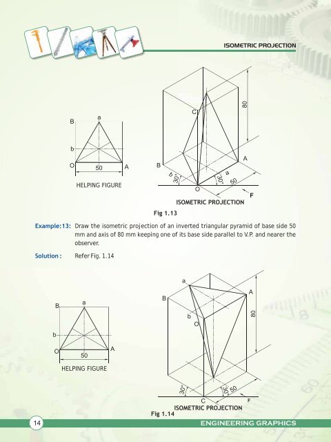
- Page 13 and 14: ISOMETRIC PROJECTION B C 30 (i) 5 b
- Page 15 and 16: ISOMETRIC PROJECTION Example 4 : So
- Page 17 and 18: ISOMETRIC PROJECTION Steps (i) Draw
- Page 19 and 20: ISOMETRIC PROJECTION Steps (i) Draw
- Page 21: ISOMETRIC PROJECTION Solution : Exa
- Page 25 and 26: ISOMETRIC PROJECTION b o B 30 m a H
- Page 27 and 28: ISOMETRIC PROJECTION Example 20 : S
- Page 29 and 30: ISOMETRIC PROJECTION Example 23 : S
- Page 31 and 32: ISOMETRIC PROJECTION 1.3.5 SPHERES
- Page 33 and 34: ISOMETRIC PROJECTION 5. Draw an iso
- Page 35 and 36: ISOMETRIC PROJECTION Steps: 1. Draw
- Page 37 and 38: ISOMETRIC PROJECTION Steps: 1. Draw
- Page 39 and 40: ISOMETRIC PROJECTION Steps: Exmple
- Page 41 and 42: ISOMETRIC PROJECTION Steps: 1. Draw
- Page 43 and 44: ISOMETRIC PROJECTION Steps: 1. Draw
- Page 45 and 46: ISOMETRIC PROJECTION 7. BELOW: CIRC
- Page 47 and 48: ISOMETRIC PROJECTION 30 66 30 15. B
- Page 49 and 50: MACHINE DRAWING Fig 2.1 b : Screw t
- Page 51 and 52: MACHINE DRAWING (v) RIGHT HAND AND
- Page 53 and 54: MACHINE DRAWING 2.4 STANDARD PROFIL
- Page 55 and 56: MACHINE DRAWING 2.4.2 METRIC THREAD
- Page 57 and 58: MACHINE DRAWING Steps involved are
- Page 59 and 60: MACHINE DRAWING 2.5 BOLTS In day to
- Page 61 and 62: MACHINE DRAWING (vii) The end of th
- Page 63 and 64: MACHINE DRAWING 2.5.3 T-BOLT Exampl
- Page 65 and 66: MACHINE DRAWING Steps Involved Exer
- Page 67 and 68: MACHINE DRAWING Example 10 : Soluti
- Page 69 and 70: MACHINE DRAWING 2.6.2 SQUARE NUTS E
- Page 71 and 72: MACHINE DRAWING Solution : Steps In
- Page 73 and 74:
MACHINE DRAWING Steps Involved Exam
- Page 75 and 76:
MACHINE DRAWING Example 15: Solutio
- Page 79 and 80:
MACHINE DRAWING 2.10 INTRODUCTION F
- Page 81 and 82:
MACHINE DRAWING 2.11.3CONVENTIONAL
- Page 83 and 84:
MACHINE DRAWING Example 18: Solutio
- Page 85 and 86:
MACHINE DRAWING Example 20: Solutio
- Page 87 and 88:
MACHINE DRAWING Exercises NOTE: Ass
- Page 89 and 90:
MACHINE DRAWING Example 24: Solutio
- Page 91 and 92:
MACHINE DRAWING Example 24: Solutio
- Page 93 and 94:
MACHINE DRAWING 2.15.1.3 DOUBLE HEA
- Page 95 and 96:
3 CHAPTER All of you have seen a bi
- Page 97 and 98:
BEARINGS 3. Plummer Block or Pedest
- Page 99 and 100:
BEARINGS Answer of Fig. 3.3 10 20 2
- Page 101 and 102:
BEARINGS Question: The figure given
- Page 103 and 104:
BEARINGS R5 R6 2 HOLES FOR BOLTS 24
- Page 105 and 106:
A BEARINGS Answer of fig 3.12 20 40
- Page 107 and 108:
BEARINGS NOTE : As per our syllabus
- Page 109 and 110:
BEARINGS Question: The figure given
- Page 111 and 112:
BEARINGS EXPLODED VIEW OF A FOOT ST
- Page 113 and 114:
BEARINGS 5 15 15 40 15 15 ENGINEERI
- Page 115 and 116:
BEARINGS FOOT STEP BEARING Ø 120
- Page 117 and 118:
ROD JOINTS DIMENSIONS OF A COTTER:
- Page 119 and 120:
ROD JOINTS SLEEVE AND COTTER JOINT:
- Page 121 and 122:
ROD JOINTS Solution of fig : 4.5 Qu
- Page 123 and 124:
ROD JOINTS Answer of fig. 4.9 50 50
- Page 125 and 126:
ROD JOINTS Question: The details of
- Page 127 and 128:
ROD JOINTS Exercise: The three view
- Page 129 and 130:
ROD JOINTS KNUCKLE JOINT OR PIN JOI
- Page 131 and 132:
ROD JOINTS Question: fig 4.19(a) sh
- Page 133 and 134:
ROD JOINTS Question: The figure 4.2
- Page 135 and 136:
ROD JOINTS Exercises: The three vie
- Page 137 and 138:
ROD JOINTS Dimensions of a Gib and
- Page 139 and 140:
ROD JOINTS 96 66 12 GIB 26 COTTER T
- Page 141 and 142:
ROD JOINTS Exercise: The two views
- Page 143 and 144:
5 CHAPTER Machines use various part
- Page 145 and 146:
TIE-ROD AND PIPE JOINTS (We have di
- Page 147 and 148:
TIE-ROD AND PIPE JOINTS Example 2:
- Page 149 and 150:
TIE-ROD AND PIPE JOINTS RH SIDE VIE
- Page 151 and 152:
TIE-ROD AND PIPE JOINTS 5.2.1.1 FEA
- Page 153 and 154:
TIE-ROD AND PIPE JOINTS (1) FLANGE
- Page 155 and 156:
TIE-ROD AND PIPE JOINTS Let us cons
- Page 157 and 158:
TIE-ROD AND PIPE JOINTS WHAT HAVE W
- Page 159 and 160:
SHAFT COUPLINGS 6.1 FLANGE COUPLING
- Page 161 and 162:
SHAFT COUPLINGS It can also be noti
- Page 163 and 164:
SHAFT COUPLINGS Ø100 Ø75 Ø50 Ø2
- Page 165 and 166:
SHAFT COUPLINGS Exercise 6.1 Fig 6.
- Page 167 and 168:
SHAFT COUPLINGS ASSEMBLED PICTORIAL
- Page 169 and 170:
SHAFT COUPLINGS Let us take another
- Page 171 and 172:
SHAFT COUPLINGS Exercise 6.2 1. FIG
- Page 173 and 174:
CHAPTER 7 7.1 INTRODUCTION PULLEYS
- Page 175 and 176:
PULLEYS So pulley is a simple machi
- Page 177 and 178:
PULLEYS Solution : Ø144 Ø126 Ø11
- Page 179 and 180:
PULLEYS Example 3 : Draw the Front