A Simplified Method for the Estimation of the Natural Roll Frequency ...
A Simplified Method for the Estimation of the Natural Roll Frequency ...
A Simplified Method for the Estimation of the Natural Roll Frequency ...

Create successful ePaper yourself
Turn your PDF publications into a flip-book with our unique Google optimized e-Paper software.
A <strong>Simplified</strong> <strong>Method</strong> <strong>for</strong> <strong>the</strong> <strong>Estimation</strong> <strong>of</strong> <strong>the</strong> <strong>Natural</strong> <strong>Roll</strong><br />
<strong>Frequency</strong> <strong>of</strong> Ships in Heavy Wea<strong>the</strong>r<br />
S.Krüger, F. Kluwe, TU Hamburg- Harburg<br />
1. Background and Motivation<br />
Several incidents where ei<strong>the</strong>r cargo was lost or <strong>the</strong> ship capsized have drawn <strong>the</strong><br />
attention <strong>of</strong> <strong>the</strong> Maritime community to <strong>the</strong> fact that under certain conditions, sudden<br />
large roll angles can occur. These sudden large roll angles typically occur in head or<br />
following seas, and <strong>the</strong>y are related to significant alterations <strong>of</strong> <strong>the</strong> stability <strong>of</strong> <strong>the</strong> ship<br />
in waves. In extreme cases, <strong>the</strong> stability may become negative on <strong>the</strong> wave crest and<br />
<strong>the</strong> ship experiences large roll angles simply due to <strong>the</strong> related stability loss.<br />
However, it is also possible that even if <strong>the</strong> ship has sufficient (or excessive) stability,<br />
large rolling angles can occur which <strong>the</strong>n result in large transversal accelerations and<br />
cargo damage. Typically, <strong>the</strong>se situations occur if <strong>the</strong> encounter frequency <strong>of</strong> <strong>the</strong><br />
waves is in resonance to <strong>the</strong> natural roll frequency <strong>of</strong> <strong>the</strong> ship. As <strong>the</strong> rolling <strong>of</strong> ships<br />
in heavy wea<strong>the</strong>r is equivalent to a <strong>for</strong>ced oscillation, it is obvious that a resonance<br />
situation will always occur if <strong>the</strong> excitation frequency is equal to <strong>the</strong> system’s<br />
eigenfrequency or to higher orders <strong>of</strong> that eigenfrequency. Most dangerous is <strong>the</strong> so<br />
called 2:1 resonance, where two pitch cycles coincide with one roll cycle. If <strong>the</strong><br />
stability <strong>of</strong> <strong>the</strong> ship is low, <strong>the</strong> related roll period takes large values and this situation<br />
can occur in following sea scenarios at slow or medium ship speeds, where also <strong>the</strong><br />
encounter period takes large values. If on <strong>the</strong> o<strong>the</strong>r hand <strong>the</strong> roll period is small due<br />
to high stability, this situation can be found at slow or medium speeds in head seas.<br />
In <strong>the</strong> so called 1:1 resonance, <strong>the</strong> eigenfrequency <strong>of</strong> <strong>the</strong> ship coincides with <strong>the</strong><br />
encounter frequency <strong>of</strong> <strong>the</strong> waves, which results in a situation where one pitch cycle<br />
coincides with one roll cycle. For typical ships, this situation is possible in followings<br />
seas at higher speeds when <strong>the</strong> stability is more on <strong>the</strong> low side. However, not all<br />
possible resonances or close to resonance situations must necessary result in <strong>the</strong><br />
occurrence <strong>of</strong> large roll angles. If <strong>the</strong> exciting <strong>for</strong>ces are sufficiently small (this means<br />
that stability alterations are below a certain threshold value) or if <strong>the</strong> roll damping is<br />
large enough, <strong>the</strong> roll motion may remain moderate. On <strong>the</strong> o<strong>the</strong>r hand it is also<br />
possible that large roll angles may occur in situations that are far beyond a<br />
resonance situation. There<strong>for</strong>e, <strong>the</strong> only accurate way to actually judge upon <strong>the</strong> roll<br />
angles in a specific head or following sea scenario is actually a full numerical<br />
simulation.<br />
On <strong>the</strong> o<strong>the</strong>r hand, <strong>the</strong>re are some practical applications where it would be useful if a<br />
decision could be made to check if a critical resonance situation is actually met. This<br />
would require a comparison <strong>of</strong> <strong>the</strong> encounter frequency (or period) and <strong>the</strong> natural<br />
roll frequency (or period) <strong>of</strong> <strong>the</strong> ship. The latter is mostly computed based on <strong>the</strong> still<br />
water situation <strong>for</strong> small roll angles. Based <strong>of</strong> <strong>the</strong> comparison <strong>of</strong> that natural roll<br />
period and <strong>the</strong> encounter period it is <strong>the</strong>n <strong>of</strong>ten decided whe<strong>the</strong>r a situation may be<br />
potentially dangerous or not. In some cases, this procedure may be successful, but<br />
<strong>the</strong>re have been also many cases been identified where this rough assumption does<br />
not lead to correct results. This is due to <strong>the</strong> fact that even in still water, <strong>the</strong> roll period
may actually depend on <strong>the</strong> roll amplitude, and fur<strong>the</strong>r, that <strong>the</strong> ship may significantly<br />
alter its roll period when operated in waves. As a matter <strong>of</strong> fact, <strong>for</strong> <strong>the</strong>se reasons it is<br />
practically not possible to judge upon a potentially dangerous situation if <strong>the</strong><br />
estimation <strong>of</strong> <strong>the</strong> ship’s natural roll period is based on <strong>the</strong> still water approach <strong>for</strong><br />
small roll angles only. But it may be useful to improve this simple estimation <strong>of</strong> <strong>the</strong><br />
natural roll period to get closer to potentially dangerous situations in possible<br />
resonances, although <strong>the</strong> method which is suggested below will not be accurate<br />
enough to fully replace a dynamic simulation.<br />
2. The Principle <strong>of</strong> <strong>Natural</strong> <strong>Roll</strong> Period Determination<br />
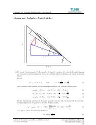
Fig. 1: Determination <strong>of</strong> natural roll period by roll decay test (left) and relevant righting<br />
levers <strong>for</strong> Stillwater, crest and trough<br />
The principle determination <strong>of</strong> <strong>the</strong> natural roll period is shown in Fig.1. The left side<br />
shows a typical roll decay test which may also (<strong>the</strong>oretically) be per<strong>for</strong>med with a full<br />
scale ship. The ship is inclined to an initial heel φo (which is small <strong>for</strong> practical<br />
reasons) and <strong>the</strong>n released. The result is an oscillation around <strong>the</strong> static heel <strong>of</strong><br />
equilibrium, and <strong>the</strong> ship oscillates in its own natural roll period. As <strong>the</strong> oscillation is<br />
damped, <strong>the</strong> amplitudes decrease. From such a test, <strong>the</strong> natural roll period and <strong>the</strong><br />
damping increment can be determined. As <strong>the</strong> ship may be idealized as a one<br />
degree <strong>of</strong> freedom oscillation system, its natural period can also <strong>the</strong>oretically be<br />
determined based on a characteristic restoring moment and a characteristic mass<br />
moment <strong>of</strong> inertia. This leads to <strong>the</strong> well known <strong>for</strong>mula <strong>of</strong> Weiss:<br />
GM denotes <strong>the</strong> metacentric height <strong>of</strong> <strong>the</strong> ship and i <strong>the</strong> roll radius <strong>of</strong> gyration, which<br />
is obtained from <strong>the</strong> mass moment <strong>of</strong> inertia around <strong>the</strong> x- axis <strong>of</strong> <strong>the</strong> ship and <strong>the</strong><br />
actual deplacement. For most ships, <strong>the</strong> roll radius <strong>of</strong> gyration (including section<br />
added mass) can be approximated by 0.4 times ship’s beam, but <strong>for</strong> some ships<br />
having a high superstructure or large amount <strong>of</strong> deck cargo, i can amount up to<br />
0.45B. It is very important to note that <strong>the</strong> <strong>for</strong>mula expresses <strong>the</strong> restoring lever by<br />
<strong>the</strong> metacentric height, which is only possible if <strong>the</strong> righting lever follows roughly <strong>the</strong>
GMφ - line. For <strong>the</strong> given roll decay test with a small initial roll angle <strong>of</strong> 5 Degree, <strong>the</strong><br />
roll oscillation takes place between <strong>the</strong> points denoted by 1 and 1’ in Fig. 1, right. For<br />
this oscillation with a small amplitude, <strong>the</strong> linearization <strong>of</strong> <strong>the</strong> righting h lever by GMφ<br />
is sufficiently accurate, as both points 1 and 1’ lie more or less exactly on <strong>the</strong> GMφline.<br />
But it is well known that <strong>the</strong> righting lever h follows that linearization only <strong>for</strong><br />
small roll angles, and consequently, <strong>the</strong> roll period determined by such kind <strong>of</strong><br />
linearization becomes <strong>the</strong>n inaccurate <strong>for</strong> a large amplitude roll motion. E.g. <strong>for</strong> a roll<br />
oscillation between <strong>the</strong> points 2 and 2’ <strong>the</strong> actual restoring moment would be<br />
significantly smaller than <strong>the</strong> linearization, as <strong>the</strong> actual righting lever is completely<br />
below <strong>the</strong> GMφ-line. Consequently, <strong>the</strong> related natural roll period must be larger.<br />
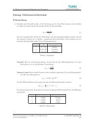
This is shown in Fig.2.<br />
Fig. 2: <strong>Roll</strong> decay test <strong>for</strong> a large initial <strong>Roll</strong> angle (left) and principle <strong>of</strong> <strong>the</strong><br />
determination <strong>of</strong> an effective GM<br />
There, a roll decay test <strong>for</strong> <strong>the</strong> same ship as Fig.1, left was simulated, but <strong>for</strong> a large<br />
initial roll angle. In comparison to Fig.1, <strong>the</strong> roll damping was reduced to keep <strong>the</strong><br />
large roll amplitudes <strong>for</strong> a longer time. The initial roll oscillation is equivalent to <strong>the</strong><br />
points denotes by 2 and 2’ in Fig. 2, right. It can clearly bee seen that initially, <strong>the</strong><br />
natural roll period amounts to roughly 3 roll cycles per 50 s (16.7s), whereas after <strong>the</strong><br />
decay <strong>of</strong> <strong>the</strong> roll amplitude <strong>the</strong> natural roll period is decreased to about 4 roll cycles in<br />
50 s (12.5s). This is in line with <strong>the</strong> non linear characteristics <strong>of</strong> <strong>the</strong> related righting<br />
lever curve in Fig.1, right: At larger heeling angles, <strong>the</strong> righting lever is significantly<br />
below <strong>the</strong> GMφ-line. Consequently, if <strong>the</strong> initial GM-value is used to determine <strong>the</strong><br />
natural roll period, this will result in a roll period being too small <strong>for</strong> a large angle roll<br />
oscillation. From <strong>the</strong> resulting roll periods it can be seen that a correct roll period<br />
determination <strong>for</strong> <strong>the</strong> large roll oscillation should be based on a GM value <strong>of</strong> about<br />
56% <strong>of</strong> <strong>the</strong> initial GM valid <strong>for</strong> small roll angles. Taking into account <strong>the</strong><br />
characteristics <strong>of</strong> <strong>the</strong> righting levers, this becomes obvious.<br />
If on <strong>the</strong> o<strong>the</strong>r hand <strong>the</strong> ship has a significant positive amount <strong>of</strong> <strong>for</strong>m stability (<strong>the</strong><br />
righting levers will be above <strong>the</strong> GMφ- line), <strong>the</strong>n <strong>the</strong> linearization <strong>of</strong> <strong>the</strong> problem with<br />
respect to <strong>the</strong> initial GM will always result in roll periods being too large.<br />
As <strong>the</strong> area below <strong>the</strong> righting lever curve is a measure <strong>of</strong> <strong>the</strong> energy which is stored<br />
in <strong>the</strong> oscillating system, a so called effective GM can be determined by <strong>the</strong> principle<br />
<strong>of</strong> area balance as shown in Fig 2 right: The effective GM <strong>for</strong> <strong>the</strong> oscillation 2 – 2’ is
determined by obtaining <strong>the</strong> same area under <strong>the</strong> righting lever curve A2 compared<br />
to A1.<br />
3. <strong>Natural</strong> <strong>Roll</strong> Periods in Waves<br />
If <strong>the</strong> ship operates in ei<strong>the</strong>r following or head seas, <strong>the</strong> still water righting lever curve<br />
is not relevant any more. The effect <strong>of</strong> <strong>the</strong> waves may be approximated by <strong>the</strong> crest<br />
curve (<strong>the</strong> wave crest is at mid ship) or <strong>the</strong> wave trough curve (<strong>the</strong> trough is at mid<br />
ship). As it can be seen from Figs 1. or 2., right, <strong>the</strong> righting levers may differ<br />
significantly from <strong>the</strong> still water curve. In extreme cases, <strong>the</strong> initial stability may even<br />
become negative on <strong>the</strong> wave crest. If <strong>the</strong> initial GM is negative, a roll period<br />
determination by <strong>the</strong> Weiss’ <strong>for</strong>mula is impossible. In this condition, <strong>the</strong> ship will not<br />
oscillate around <strong>the</strong> unstable upright condition, but around <strong>the</strong> static equilibrium<br />
which is denoted by EQ in Figs.1 or 2. But with respect to <strong>the</strong> roll motion in waves,<br />
<strong>the</strong> oscillation around that static equilibrium is not <strong>of</strong> interest, as <strong>the</strong> ship in waves<br />
oscillates roughly around <strong>the</strong> upright position at about zero heel. With respect to that<br />
condition, <strong>the</strong> momentary value <strong>of</strong> <strong>the</strong> roll acceleration is not obtained from an<br />
oscillation, but simply from <strong>the</strong> <strong>for</strong>mula:<br />
The roll acceleration is obtained from an effective heeling moment (based on <strong>the</strong><br />
negative righting lever and <strong>the</strong> damping) and <strong>the</strong> vessel simply heels to <strong>the</strong> static<br />
equilibrium EQ and <strong>the</strong>n starts to oscillate around this condition. For this oscillation<br />
around that equilibrium, <strong>the</strong> Weiss’ <strong>for</strong>mula could again be used. But as mentioned<br />
above, this kind <strong>of</strong> oscillation is not <strong>of</strong> interest in this context. Because <strong>for</strong> all<br />
situations where <strong>the</strong> ship is close to a critical resonance, <strong>the</strong> crest is at mid ship when<br />
<strong>the</strong> vessel is nearly in an upright position, and <strong>the</strong> vessel simply starts to heel close<br />
to <strong>the</strong> static equilibrium. The ship is <strong>the</strong>n rightend up again when <strong>the</strong> crest passed<br />
towards her end. In this condition, <strong>the</strong> trough curve is valid. As in this position <strong>the</strong><br />
ship has sufficient positive initial stability, <strong>the</strong> roll oscillation is again well defined.<br />
So <strong>the</strong> vessel permanently is in one extreme situation where <strong>the</strong> roll oscillation<br />
around <strong>the</strong> upright position is not existent or <strong>the</strong> o<strong>the</strong>r one where <strong>the</strong> roll oscillation is<br />
governed by <strong>the</strong> trough righting levers. There<strong>for</strong>e, it is suggested to use an averaged<br />
crest- trough righting lever curve instead <strong>of</strong> <strong>the</strong> still water righting lever to better take<br />
into account <strong>the</strong> effects <strong>of</strong> <strong>the</strong> sea state. This concept follows a well known approach<br />
by Wendel that was used to define <strong>the</strong> stability standard <strong>of</strong> <strong>the</strong> German Navy BV<br />
1033. There<strong>for</strong>e, according to <strong>the</strong> present proposal, <strong>the</strong> natural roll period <strong>of</strong> a ship<br />
in a natural seaway should be determined as follows:<br />
• The natural roll period shall be based on an artificial stability curve which is <strong>the</strong><br />
average <strong>of</strong> <strong>the</strong> crest and trough righting lever curve in a reference wave.<br />
• Not <strong>the</strong> initial GM shall be used as input <strong>for</strong> <strong>the</strong> Weiss <strong>for</strong>mula, but an effective<br />
GM which is based on <strong>the</strong> area equality below this artificial righting lever curve<br />
and <strong>the</strong> linearization <strong>for</strong> a certain angle <strong>of</strong> interest.
This concept is tested on two extreme cases in <strong>the</strong> following sections.<br />
4. Test applications<br />
4.1. Negative <strong>for</strong>m stability<br />
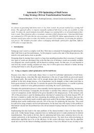
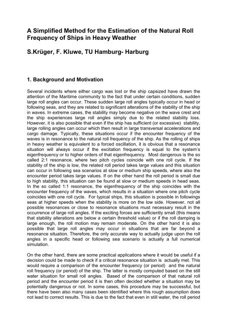
Fig. 3: Polar diagrams <strong>of</strong> numerical capsizing simulation <strong>of</strong> a capsizing accident (left)<br />
and related righting levers (right).<br />
The concept is applied to a full scale capsizing accident <strong>of</strong> a RoRo ferry. The ship<br />
capsized in following seas at about 16 kn speed and an encounter angle <strong>of</strong> abt.15<br />
degree in waves having a significant period <strong>of</strong> abt. 7.5-8.5s (equivalent significant<br />
wave length 88- 113m). The polar diagrams, left, show <strong>the</strong> limiting significant wave<br />
heights as function <strong>of</strong> course and speed which lead to a capsize. The numerical<br />
simulations <strong>of</strong> that accident (Fig.2, left) show two areas in following seas where <strong>the</strong><br />
ship is extremely endangered: One area at about 6-8 knots and one area at about<br />
15- 17 knots. These are related to <strong>the</strong> typical resonances, namely 1:1 at about 16 kn<br />
and 2:1 at about 6 knots (<strong>the</strong> rough centre <strong>of</strong> <strong>the</strong>se areas). From Fig. 2, right, <strong>the</strong> fact<br />
can be derived that <strong>the</strong> initial GM <strong>of</strong> <strong>the</strong> still water righting lever curve amounts to<br />
1.68 m and is valid <strong>for</strong> small angles only. Based on <strong>the</strong> still water righting lever curve<br />
and <strong>the</strong> related initial GM, a still water natural roll period <strong>of</strong> 13.3. s can be computed<br />
<strong>for</strong> small angles. If <strong>the</strong> 1:1 or 2:1 resonance in a wave having a significant period <strong>of</strong><br />
8.5 s shall be met, this would result in <strong>the</strong> following critical ship speeds:<br />
The 1:1 following sea resonance should be found at a speed <strong>of</strong> 9.63 kn, and <strong>the</strong> 2:1<br />
should not be possible in following seas (it is computed at –7.5 kn which means head<br />
seas). Compared to <strong>the</strong> directly computed resonance areas, <strong>the</strong>se results are<br />
completely wrong. The reason <strong>for</strong> this becomes clear when <strong>the</strong> righting levers are<br />
regarded, as <strong>the</strong> still water curve does not at all represent ei<strong>the</strong>r <strong>the</strong> trough or crest<br />
condition, and that fur<strong>the</strong>r, <strong>the</strong> initial GM does not represent even <strong>the</strong> still water<br />
stability at all.<br />
Based on <strong>the</strong> approach suggested in this paper, <strong>the</strong> problem should be linearized<br />
based on <strong>the</strong> crest trough average (<strong>the</strong> magenta curve in Fig. 3, right) and <strong>the</strong> area<br />
equivalent. This would in fact lead to an effective GM <strong>of</strong> about 0.68m (if an angle <strong>of</strong><br />
40 Degree is used as reference) and a natural roll period <strong>of</strong> 21s. Based on <strong>the</strong>se 21s
natural roll period computed <strong>for</strong> 113 m wave length and 5m wave height, <strong>the</strong> 1:1<br />
following sea resonance is computed at 15.9 knots and <strong>the</strong> 2:1 resonance at 5.1<br />
knots. This fits much better to <strong>the</strong> real situation and shows that a simple approach<br />
can in principle give useful results if <strong>the</strong> problem is linearized more accurately.<br />
4.2. Positive <strong>for</strong>m stability<br />
Fig. 4: Polar diagrams <strong>of</strong> numerical roll motion simulation <strong>of</strong> a cargo loss accident<br />
(left) and related righting levers (right). The right polar diagram is valid <strong>for</strong> a roll angle<br />
<strong>of</strong> 15 Degree, <strong>the</strong> left <strong>for</strong> a roll angle <strong>of</strong> 40 Degree.<br />
As alternative test case, a cargo loss event is analyzed. Large roll angles on a large<br />
container vessel occurred in following seas at a speed <strong>of</strong> about 21 kn, encounter<br />
angle 10 Degree, equivalent significant wave length about 170m, significant wave<br />
height abt 5-6 m. The polar plot indicates <strong>the</strong> 1:1 following sea resonance clearly at<br />
about 18 kn and <strong>the</strong> 2:1 following sea resonance roughly at about 4-5 knots. Based<br />
on <strong>the</strong> still water righting lever curve and an initial GM <strong>of</strong> 0.65m, a natural roll<br />
Stillwater roll period <strong>of</strong> 32.1 s is calculated (<strong>for</strong> small angles). Based on this value, <strong>the</strong><br />
1:1 resonance should be found at 21.7 kn and <strong>the</strong> 2:1 at 11.30 knots. These values<br />
are actually not as bad as <strong>for</strong> <strong>the</strong> previous case, but still remarkably inaccurate It<br />
must be noted that <strong>the</strong> difference between <strong>the</strong> still water righting lever and <strong>the</strong><br />
trough crest average is not very large <strong>for</strong> this example, which makes <strong>the</strong><br />
approximation better than be<strong>for</strong>e. However, if <strong>the</strong> natural roll period is determined<br />
from <strong>the</strong> crest – trough average and 40 degree area equivalent, this results in an<br />
effective GM <strong>of</strong> 1.1 m and a roll period in waves <strong>of</strong> about 24.4 s. Based on <strong>the</strong>se 24.4<br />
s, <strong>the</strong> 1:1 resonance should be at 18.7 kn and <strong>the</strong> 2:1 resonance should be at about<br />
4.7 knots. Both values are much better in line with <strong>the</strong> numerical simulations <strong>for</strong><br />
both large and smaller roll angles compared to <strong>the</strong> estimation by using still water<br />
initial metacentric height.<br />
4. Conclusions<br />
A simple straight<strong>for</strong>ward method was suggested to better estimate <strong>the</strong> natural roll<br />
period <strong>of</strong> a ship in heavy wea<strong>the</strong>r. The method is still based on <strong>the</strong> linearization <strong>of</strong> <strong>the</strong><br />
roll motion in waves, but uses an effective GM which is based on <strong>the</strong> crest trough
average <strong>of</strong> <strong>the</strong> righting lever curves in a specific reference wave. The reference wave<br />
length may be derived from <strong>the</strong> significant period <strong>of</strong> a given wave spectrum. As <strong>the</strong><br />
method still linearizes <strong>the</strong> roll problem, <strong>the</strong> results are not correct enough to actually<br />
replace fully nonlinear simulations. But two practical applications have shown that <strong>the</strong><br />
estimation <strong>of</strong> critical resonance situations will in most cases be more reliable than a<br />
simple guess based on <strong>the</strong> still water roll period <strong>for</strong> small roll angles.