Outcrop/Behind Outcrop Characterization of Deepwater (Turbidite ...
Outcrop/Behind Outcrop Characterization of Deepwater (Turbidite ...
Outcrop/Behind Outcrop Characterization of Deepwater (Turbidite ...

You also want an ePaper? Increase the reach of your titles
YUMPU automatically turns print PDFs into web optimized ePapers that Google loves.
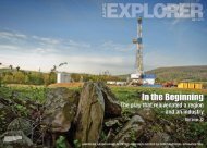
2001-02 AAPG Distinguished Lecture<br />
Funded by the AAPG Foundation<br />
through the J. Ben Carsey Memorial Endowment<br />
<strong>Outcrop</strong>/<strong>Behind</strong> <strong>Outcrop</strong><br />
<strong>Characterization</strong> <strong>of</strong> <strong>Deepwater</strong><br />
(<strong>Turbidite</strong>) Petroleum Reservoir<br />
Analogs: Why and How<br />
Roger M. Slatt<br />
University <strong>of</strong> Oklahoma<br />
Norman, Oklahoma
© 2001 The American Association <strong>of</strong><br />
Petroleum Geologists and Roger M. Slatt<br />
No slides, figures, text or other matter<br />
contained herein may be reproduced without<br />
the written permission <strong>of</strong> both the American<br />
Association <strong>of</strong> Petroleum Geologists and<br />
Roger M. Slatt
ENGINEERING DEFINITION: Drilling a well <strong>of</strong>fshore into<br />
a basin fill in present-day water depths greater than 500m<br />
(1500ft) above the mud line (ocean floor).
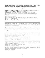
<strong>Deepwater</strong> (>500m) discovered reserves<br />
1978<br />
1980<br />
Cumulative Gas<br />
Cumulative Oil/Cond.<br />
Cumulative BBOE in Ultra-Deep<br />
Water (>2000m)<br />
Portion <strong>of</strong> BBOE<br />
Developed or under<br />
development<br />
1982<br />
1984<br />
1986<br />
1988<br />
Year<br />
1990<br />
1992<br />
1994<br />
1996<br />
7 BBOE per year<br />
1998<br />
Gas<br />
Oil<br />
Developed<br />
UDW<br />
2000<br />
50<br />
40<br />
30<br />
20<br />
10<br />
0<br />
BBOE<br />
Discoveries<br />
mainly from:<br />
Gulf <strong>of</strong> Mexico,<br />
<strong>of</strong>fshore W.<br />
Africa and<br />
Brazil, N. Sea,<br />
SW shelf<br />
Australia, SE<br />
Asia<br />
< 25% Developed<br />
or In Development<br />
Source:<br />
Various
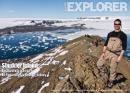
<strong>Deepwater</strong> Discovered Reserves<br />
>500m water depth<br />
as <strong>of</strong> Sept. 2001<br />
4<br />
3,0<br />
10<br />
8,6<br />
US GoM<br />
Taumalipas<br />
& Campeche<br />
Recoverable<br />
Resources in BBOE<br />
(green= oil, red = gas)<br />
Scotian &<br />
Jeanne D’Arc<br />
Trinidad<br />
Brazil<br />
Faroes<br />
White Zone<br />
WoS<br />
Morocco<br />
0,9<br />
10,9<br />
12<br />
0,5<br />
12,4 13<br />
3.6 3,0<br />
Mid-Norway<br />
0,6<br />
Egypt<br />
Nigeria<br />
Eq. Guinea<br />
Gabon<br />
Congo<br />
Angola<br />
S. Africa<br />
Italy<br />
2.0<br />
So. Caspian<br />
2,0 0,9<br />
1,8<br />
2.7<br />
Tanzania<br />
Mozambique<br />
E. India<br />
Total Discovered<br />
57 BBOE<br />
37 BBO + 120 TCF<br />
6,8<br />
7<br />
0,1<br />
NWS & ZOCA<br />
Sakhalin<br />
NW & SE Borneo<br />
Taranaki<br />
Areas <strong>of</strong> Prospective <strong>Deepwater</strong><br />
and Ultra-<strong>Deepwater</strong> Basins<br />
Data Sources: Pettingill (1999), various others
GEOLOGIC DEFINITION: Clastic sediments transported beyond the shelf<br />
edge into deep water by sediment gravity flow processes and deposited on<br />
the continental slope and in the basin. They are later buried and become part<br />
<strong>of</strong> a basin fill: Engineering and geologic ‘deep water’ are usually the same.<br />
Sp<br />
SIX RESERVOIR TYPES
Distal levee or<br />
TYPE III<br />
OVERBANK<br />
OVERBANK SLUMP<br />
SUBMARINE CHANNEL<br />
SYSTEM<br />
AGGRADING CHANNEL-LEVEE<br />
COMPLEX<br />
Splay<br />
CHANNEL PROXIMAL<br />
LEVEE<br />
CHANNEL<br />
LEVEE<br />
(Roberts and Compani,<br />
1996)
3D SEISMIC HORIZON SLICE<br />
Offshore Angola<br />
next picture<br />
(Provided by Kolla)
3D Seismic line, <strong>of</strong>fshore Angola<br />
Black = positive seismic reflection<br />
Purple = negative seismic reflection<br />
Kolla et al., 2001
3D Seismic line, <strong>of</strong>fshore Angola<br />
Black = positive seismic reflection<br />
Purple = negative seismic reflection<br />
Discovery Well<br />
Kolla et al., 2001
APPRAISAL & DEVELOPMENT<br />
• HOW BIG IS THE RESERVOIR?<br />
• HOW WILL THIS RESERVOIR STYLE PERFORM?<br />
• HOW WIDELY MUST WE SPACE OUR<br />
EXPENSIVE DEVELOPMENT WELLS?<br />
• SHOULD WE DRILL A VERTICAL, SLANT, OR<br />
HORIZONTAL WELL??<br />
• HOW CAN WE FAST-TRACK DEVELOPMENT OF<br />
THIS RESERVOIR?<br />
• WHAT WENT WRONG?
HOW CAN OUTCROPS HELP ANSWER<br />
THOSE TOUGH Con QUESTIONS??<br />
BUILDING A SCALED GEOLOGIC MODEL<br />
FROM OUTCROPS:<br />
•Sheet Sandstone Reservoirs<br />
•Leveed Channel Sandstone Reservoirs<br />
Lets study the Cretacous Lewis Shale in Wyoming!!
TOOLS AND TECHNIQUES FOR<br />
OUTCROP CHARACTERIZATON<br />
STANDARD RECENT ADDITIONS<br />
•Brunton Compass •Photomosaics on Workstation<br />
•Hand Lens •<strong>Outcrop</strong> gamma-ray/sonic logs<br />
•Jacobs Staff •<strong>Behind</strong>-outcrop logging/coring<br />
•Tape Measure •Ground Penetrating Radar (GPR)<br />
•Rock Hammer •Global Positioning System (GPS)<br />
•Camera •Ultra-shallow seismic behind<br />
outcrop<br />
•<strong>Outcrop</strong> Minipermeameter<br />
•3D Imaging
West<br />
Cretaceous Lewis Shale, Wyoming<br />
“Bashful outcrops”<br />
12<br />
Spine I<br />
S1 and S2 are continuous Lewis sheet sandstones<br />
CC is Lewis leveed channel complex on Spine I<br />
F is shallow marine Fox Hills<br />
North
West<br />
Cretaceous Lewis Shale, Wyoming<br />
Spine I<br />
S1 and S2 are continuous Lewis sheet sandstones<br />
CC is Lewis leveed channel complex on Spine I<br />
F is shallow marine Fox Hills<br />
North
Sheet Sandstones:<br />
Laterally continuous<br />
for miles: i.e. good<br />
potential reservoir<br />
facies; individual<br />
sandstone intervals<br />
are separated by<br />
shales.<br />
(Witton, 1999)<br />
Lith<strong>of</strong>acies A<br />
Sheet Sandstones
West<br />
Cretaceous Lewis Shale, Wyoming<br />
Spine I<br />
Laterally continuous shales in between<br />
Laterally continuous sandstones<br />
S1 and S2 are continuous Lewis sheet sandstones<br />
CC is Lewis leveed channel complex on Spine I<br />
F is shallow marine Fox Hills<br />
North
West<br />
Cretaceous Lewis Shale, Wyoming<br />
Spine I<br />
S1 and S2 are continuous Lewis sheet sandstones<br />
CC is Lewis leveed channel complex on Spine I<br />
F is shallow marine Fox Hills<br />
North
Channel-fill #1<br />
Sandstone<br />
Spine I<br />
(yellow line is app. 450m on ground; 120m <strong>of</strong> strat. section)<br />
Well-------<br />
#2 #3 #4 #5 #6<br />
10 Channel-fill sandstones, each separated<br />
by shale/mudstone breaks:i.e. discontinuous<br />
reservoirs; not so easy to develop as reservoirs
<strong>Behind</strong>-outcrop drilling for logs and core
Gamma Ray<br />
Where’s the<br />
10 sands??<br />
Core<br />
GR<br />
Bulk Density<br />
Sonic Dt<br />
Neutron Porosity<br />
Core Porosity<br />
CSM Strat<br />
Test #61<br />
Core and<br />
Log Data<br />
<strong>Outcrop</strong><br />
Subcrop
Channel-fill #1<br />
Sandstone<br />
Well-------<br />
#2 #3 #4 #5 #6<br />
Where did the Channel-fill #1 Sandstone go?? Meander loop <strong>of</strong><br />
sinuous channel??
Channel-fill #1<br />
Sandstone<br />
Well-------<br />
#2 #3 #4 #5 #6<br />
Where did the Channel-fill #1 Sandstone go?? Meander loop <strong>of</strong><br />
sinuous channel??
Thin-bedded,<br />
extra-channel<br />
or levee<br />
facies<br />
Rain gulley
Spine I, Lewis Shale<br />
Sinuosity not<br />
shown in model<br />
#4<br />
#3<br />
Channel-fill #1<br />
Sandstone -----------<br />
Width <strong>of</strong> channel<br />
Complex app. 500m<br />
#6 #7 #8<br />
#9<br />
#10<br />
#2<br />
#5<br />
CSM Strat Test well<br />
Sheet sandstones<br />
Thin levee beds<br />
not shown in<br />
model<br />
Channel complex
Laterally discontinuous<br />
channel-fill sandstone<br />
Channel-fill #1<br />
Sandstone<br />
(150m across in outcrop)
Channel-fill #1 Sandstone; oblique view<br />
across channel-fill<br />
X-bedded sands<br />
Massive sands w/ fluid escape structures<br />
Red = shale clast cong. Brown = sandy debrites
Cross-bedded sandstone
Shale clast conglomerate(debrite)<br />
Interbedded turbidites and debrites<br />
<strong>Turbidite</strong>
Laterally discontinuous<br />
channel-fill sandstone<br />
Channel-fill #1<br />
Sandstone<br />
(150m across in outcrop)
Margin <strong>of</strong> Channel Sandstone #1<br />
Ground-penetrating radar (GPR) line across channel margin<br />
showing sharp channel boundary and internal channel-slump<br />
features<br />
(Young et al,, 1999)
15<br />
ft<br />
Complex Channel margin<br />
S N<br />
P5<br />
Station 26<br />
0<br />
6.5<br />
9.8<br />
13<br />
16<br />
Channel margin is slumped,<br />
with channel sand injections<br />
into adjacent thin-beds<br />
Approximate depth<br />
(ft)<br />
H:V ~ 1:1
Thin bedded Sandstones/Mudstones<br />
Slumped<br />
beds<br />
Channel Sandstone
Thin bedded Sandstones/Mudstones<br />
Slumped<br />
beds<br />
Channel Sandstone<br />
No communication<br />
across slumped zone<br />
in reservoir analogs
Spine I, Lewis Shale<br />
#4<br />
#3<br />
Channel-fill #1<br />
Sandstone -----------<br />
Width <strong>of</strong> channel<br />
Complex app. 500m<br />
#6 #7 #8<br />
#9<br />
#10<br />
#2<br />
#5<br />
CSM Strat Test well<br />
Sheet sandstones<br />
Channel complex
Spine I, Lewis Shale<br />
#4<br />
#3<br />
Channel-fill #1<br />
Sandstone -----------<br />
Width <strong>of</strong> channel<br />
Complex app. 500m<br />
#6 #7 #8<br />
#9<br />
#10<br />
#2<br />
#5<br />
CSM Strat Test well<br />
Sheet sandstones<br />
Channel complex
Spine I, Lewis Shale<br />
#4<br />
#3<br />
Channel-fill #1<br />
Sandstone -----------<br />
Width <strong>of</strong> channel<br />
Complex app. 500m<br />
#6 #7 #8<br />
#9<br />
#10<br />
#2<br />
#5<br />
CSM Strat Test well<br />
Sheet sandstones<br />
Channel complex<br />
Complex channel<br />
margin
3D Seismic line, <strong>of</strong>fshore Angola<br />
Black = positive seismic reflection<br />
Purple = negative seismic reflection<br />
Multiple channel sandstones separated<br />
by mudstones<br />
Sheet Sandstones separated by mudstones<br />
Kolla et al., 2001
3D Seismic line, <strong>of</strong>fshore Angola<br />
Black = positive seismic reflection<br />
Purple = negative seismic reflection<br />
Discovery Well<br />
Kolla et al., 2001
Well<br />
Black = positive seismic reflection<br />
Purple = negative seismic reflection<br />
Kolla et al., 2001
Con<br />
HOW CAN OUTCROPS HELP ANSWER<br />
THOSE TOUGH QUESTIONS??<br />
BUILDING A SCALED GEOLOGIC MODEL<br />
FROM OUTCROPS:<br />
•Thin-bedded levee reservoirs<br />
Lets study the Miocene Mt. Messenger Formation<br />
in New Zealand!!
Distal levee or<br />
TYPE III<br />
OVERBANK<br />
OVERBANK SLUMP<br />
SUBMARINE CHANNEL<br />
SYSTEM<br />
AGGRADING CHANNEL-LEVEE<br />
COMPLEX<br />
Splay<br />
CHANNEL PROXIMAL<br />
LEVEE<br />
CHANNEL<br />
LEVEE<br />
(Roberts and Compani,<br />
1996)
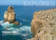
Miocene Mt. Messenger Formation, Taranaki Basin,<br />
New Zealand: Cliff is 250m high and several km long<br />
Two<br />
Wells<br />
H.R.<br />
Seismic<br />
PHOTOMOSAICS FROM HELICOPTER; WELLS; CORES; LOGS; HIGH-<br />
RESOLUTION SHALLOW SEISMIC; MEASURED SECTIONS
Depositional interval or bed scale
Pleistocene-----------<br />
(brown)<br />
--D<br />
C = channel fill (upward dip decrease); P = proximal<br />
levee (high & variable angle dips); D = distal levee;<br />
C<br />
P
Distal levee bed sets (lower & uniform dip angles)
<strong>Behind</strong>outcrop<br />
dipmeter<br />
logs (by<br />
Schlumberger)<br />
Channel<br />
fill<br />
Distal levee/<br />
overbank<br />
Proximal<br />
levee<br />
(Slatt et al.,<br />
1998)
Levee beds<br />
3D Seismic line, <strong>of</strong>fshore Angola<br />
Black = positive seismic reflection<br />
Purple = negative seismic reflection<br />
Multiple channel sandstones separated<br />
by mudstones<br />
Levee beds<br />
Sheet Sandstones separated by mudstones<br />
Kolla et al., 2001
Well<br />
Black = positive seismic reflection<br />
Purple = negative seismic reflection<br />
Kolla et al., 2001
L Sand, Ram/Powell Field, Gulf <strong>of</strong> Mexico: comprises channel,<br />
proximal, & distal levee facies.<br />
West Ram/Powell Field<br />
East<br />
4.0 s<br />
4.5 s<br />
Tertiary Cretaceous Unconformity<br />
J sand L sand<br />
3363 ft<br />
N sand<br />
M sand<br />
(Clemenceau et al., 2000)
west east<br />
channel<br />
wet<br />
datum base <strong>of</strong> sand<br />
Ram Powell ‘L’ Sand<br />
proximal levee distal levee<br />
100 ft<br />
low resistivity gas pay<br />
(Clemenceau et al, 2000)<br />
2 ohms
west east<br />
channel<br />
wet<br />
datum base <strong>of</strong> sand<br />
Ram Powell ‘L’ Sand<br />
Inferred complex<br />
channel margin<br />
proximal levee distal levee<br />
100 ft<br />
low resistivity gas pay<br />
(Clemenceau et al, 2000)<br />
2 ohms
west east<br />
channel<br />
wet<br />
datum base <strong>of</strong> sand<br />
Ram Powell ‘L’ Sand<br />
Inferred complex<br />
channel margin<br />
proximal levee distal levee<br />
100 ft<br />
low resistivity gas pay<br />
(Clemenceau et al, 2000)<br />
2 ohms
(Clemenceau et al., 2000)
Amplitude<br />
proximal levee<br />
Channel<br />
high<br />
low<br />
3 miles<br />
A<br />
B<br />
C<br />
A-1(horizontal)<br />
Seismic line Fig. 5<br />
Ram Powell ‘L’ Sand<br />
E<br />
D<br />
GOC<br />
A<br />
B<br />
C<br />
D<br />
E<br />
L-1 LKO<br />
wet well<br />
A5<br />
A8st1<br />
A8st2<br />
A17<br />
957-1st2<br />
well test<br />
distal<br />
levee-overbank<br />
Drilling Strategy: Horizontal well in proximal levee beds, parallel to channel:<br />
“Well performance N exceeded expectations with a peak flow rate <strong>of</strong> 105mmcfgd<br />
and 9600 bopd”<br />
100 ft contour interval<br />
(Clemenceau et al, 2000)
WHAT IF YOU DON’T HAVE<br />
SEISMIC????<br />
BOREHOLE IMAGE LOGS WILL ALLOW YOU TO<br />
DIFFERENTIATE FACIES FOR VOLUMETRICS<br />
AND DRILLING STRATEGY (i.e. conventional<br />
well logs won’t differentiate facies with any degree<br />
<strong>of</strong> certainty)<br />
-Wellbore and behind-outcrop borehole image logs<br />
(STAR TM and FMI tm ) verify this in Lewis Shale<br />
and Mt. Messenger!!<br />
TM Baker-Hughes<br />
tm Schlumberger
Borehole<br />
Image<br />
Log,<br />
Lewis Sh.<br />
Debrites<br />
and<br />
<strong>Turbidite</strong>s =<br />
Channel -fill<br />
sandstones<br />
(Witton, 2000)
Borehole<br />
Image<br />
Log,<br />
Lewis Sh.<br />
<strong>Turbidite</strong>s<br />
only =<br />
Sheet<br />
Sandstones<br />
(Witton, 2000)
Levee beds<br />
from Mt.<br />
Messenger<br />
Fm. New<br />
Zealand
Well<br />
Well
Well<br />
Well
YET ANOTHER USE OF OUTCROPS<br />
Con<br />
•3D GEOLOGIC MODELING FOR<br />
VISUALIZATION, RESERVOIR<br />
PERFORMANCE PREDICTION &<br />
WELL PLACEMENT<br />
Lets study the Penn. Jackfork Group in Arkansas!!
Dipping sheet<br />
sands (colors)<br />
separated<br />
by shales<br />
Gulf <strong>of</strong> Mexico stacked sheet sand reservoirs<br />
(Kendrick, 2000)
CAVE<br />
3D Seismic data<br />
volume<br />
Person<br />
Dorn et.al, 2001<br />
Walk-in CAVE’s are excellent, but expensive!!
GEOLOGIC MODELING AREA, ARKANSAS: THE INEXPENSIVE<br />
CAVE IS CALLED AN OUTCROP!!!<br />
55
OUTCROP GEOLOGIC MODELING AREA, ARKANSAS<br />
55<br />
A
OUTCROP GEOLOGIC ‘RESERVOIR’ MODEL<br />
‘UNCONFORMITY TOPSEAL’<br />
‘Sealing<br />
A B C<br />
Shale’<br />
‘RESERVOIR SANDSTONES’<br />
‘OIL-WATER CONTACT’<br />
OUTCROP ‘A’<br />
“Imagination is more powerful than knowledge”<br />
Albert Einstein
A<br />
Zone Net/Gross Por.(%) Perm.(md) Sw (%)<br />
A 0.70 29 1000 20<br />
B 0.40 26 300 20<br />
C 0.95 29 1000 20<br />
D 0.96 30 2000 20<br />
Oil/water contact<br />
C SHALE<br />
D<br />
B<br />
FAULT<br />
GEOLOGIC<br />
RESERVOIR<br />
MODEL FOR<br />
SIMULATION:<br />
Dipping sandstones<br />
with unconformity<br />
topseal; Layers<br />
separated by<br />
sealing shales
Zone Net/Gross Por.(%) Perm.(md) Sw (%)<br />
A 0.70 29 1000 20<br />
B 0.40 26 300 20<br />
C 0.95 29 1000 20<br />
D 0.96 30 2000 20<br />
Oil/water<br />
contact<br />
GEOLOGIC<br />
RESERVOIR<br />
MODEL FOR<br />
SIMULATION:<br />
Dipping sandstones<br />
with unconformity<br />
topseal; Layers<br />
separated by<br />
sealing shales
A<br />
Oil/water contact<br />
C<br />
B<br />
WELL PLACEMENT<br />
FOR SIMULATION:<br />
On each fault block:<br />
-Vertical well thru D<br />
-Vertical well thru B<br />
-Horizontal well thru<br />
B,C,D.<br />
D<br />
Sh
A<br />
Oil/water contact<br />
C<br />
B<br />
AFTER SIMULATION:<br />
Most oil out <strong>of</strong> horizontal<br />
well, then Zone D, then<br />
Zone B.<br />
D<br />
SH
VALUE OF OUTCROPS<br />
Con<br />
•SEEING IS BELIEVING<br />
•BUILD SCALED GEOLOGIC MODEL<br />
FOR SUBSURFACE PREDICTION:<br />
-FACIES<br />
-TRENDS<br />
-GEOMETRIES<br />
-DIMENSIONS<br />
-CONTINUITY/CONNECTIVITY<br />
•3D GEOLOGIC MODELING FOR SIMULATION<br />
•IMPROVED & MORE ECONOMIC:<br />
-WELL SPACING & PLACEMENT<br />
-RESERVOIR PERFORMANCE PREDICTION
2001-02 AAPG Distinguished Lecture<br />
Funded by the AAPG Foundation<br />
through the J. Ben Carsey Memorial Endowment<br />
<strong>Outcrop</strong>/<strong>Behind</strong> <strong>Outcrop</strong><br />
<strong>Characterization</strong> <strong>of</strong> <strong>Deepwater</strong><br />
(<strong>Turbidite</strong>) Petroleum Reservoir<br />
Analogs: Why and How<br />
Roger M. Slatt<br />
University <strong>of</strong> Oklahoma<br />
Norman, Oklahoma