Installation Manual
Installation Manual
Installation Manual

Create successful ePaper yourself
Turn your PDF publications into a flip-book with our unique Google optimized e-Paper software.
<strong>Installation</strong> <strong>Manual</strong><br />
for KAGO rail contact clamps<br />
and KAGO cable fastening clamps
List of contents<br />
1. Does the clamp fit your rail profile? 4<br />
2. <strong>Installation</strong> of rail contact clamps 6<br />
3. <strong>Installation</strong> of cable fastening clamps 7<br />
4. Removal of clamps 8<br />
5.1. Cable installation for types E2 and E3 9<br />
5.2. Cable installation for type E4 10<br />
5.3. Cable installation for type E5 11<br />
5.4. Cable installation for types GI and EI 12<br />
5.5. Cable installation for type EA 13<br />
5.6. Cable laying of railbonds 14<br />
6.1. Why testing of rail contact clamps? 15<br />
6.2. Test instructions before reuse 16<br />
6.3. Groove cleaning and spring checking 17<br />
3
1. Does the clamp fit your rail profile?<br />
Important: Please read carefully!<br />
Hundreds of different rails are in use worldwide! The already developed<br />
basic types of KAGO clamps integrate this variety to a large<br />
extent.<br />
The basic types differ in two essential features:<br />
Firstly in length and number of the existing slots, by which it is possible<br />
to cover different rail base widths. See example below:<br />
1. slot: 125 mm<br />
2. slot: 140 mm<br />
3. slot: 150 mm<br />
Basic type C<br />
Suitable for the following rails:<br />
- 1 st slot: S49=Form B, S54, SBB I, DSB 45,UIC54E = SBB IV =<br />
Form C.<br />
- 2 nd slot: UIC54 = SBB III = 54 kg, 98lb, 109lb, 110A, 113A,<br />
113 lb, U36, U50, EB50T, Ri35G=35GP<br />
- 3 rd slot: UIC60 = SBB VI = UNI60, Ri55, Ri53<br />
4
Secondly the clamps differ in<br />
their opening, by which the different<br />
rail base forms are covered.<br />
See measure „x“ on the right:<br />
Because the different clamps are often hardly distinguishable at first<br />
sight, we have marked the bottom, namely with the letters „A“, „C“,<br />
„D“, „E“, „I“, „J“, „K”, „N“, „P“, „R81“, „R82“, „T“, „U“, „V” „W“, „Y50N“<br />
or „Y60“ etc.<br />
Always make sure you are mounting the correct clamp which is<br />
perfectly suitable for your rail!<br />
In case of uncertainty please refer to the „KAGO Clamp Directory“<br />
which includes information about the different basic clamp types as<br />
well as the most common rails.<br />
Caution: If clamps are mounted on unsuitable rails, their function<br />
is not guaranteed due to incomplete fitting or insufficient<br />
clamping pressure! The worst case is overstretching (for example<br />
at switches) which could even result in clamp breakage!<br />
5
2. <strong>Installation</strong> of rail contact clamps<br />
Caution: Use a hammer with the ideal weight between<br />
1 and 2 kilograms for mounting and removal. It<br />
must not be heavier than 2 kg, otherwise the clamp<br />
or the spring could be damaged.<br />
6<br />
Place the clamp on the rail base<br />
and give it a few light taps (I) so<br />
that it gets a bit of tension and<br />
starts to grip. Pay attention that<br />
you hit the curve and not the<br />
head of the clamp while hammering!<br />
Afterwards three hard blows will normally do to mount the clamp<br />
sufficiently. After reaching the stop (II), the clamp will automatically<br />
click into place at the rail base‘s lower edge (III). If the clamp jumps<br />
back – which can above all happen with brand-new clamps –, repeat<br />
the procedure: At first use light taps, then hit hard. Make sure<br />
the clamp is gripping properly at the front and back!<br />
Don‘t forget: The clamp functions like a spring and therefore has a<br />
tremendous inherent strength. This is necessary, so that the teeth<br />
bite firmly and permanently into the rail, through brake dust, grease,<br />
rust or other residue.<br />
Please wear safety goggles and ensure that nobody is standing in<br />
front of or behind you during the whole mounting procedure!<br />
Duration of installation: KAGO contact clamps are mainly used for<br />
temporary electric connections. However they can also stay built in<br />
permanently for years or even decades without any problem. Even<br />
the most intense clamp vibrations can do no harm, assuming correct<br />
installation directions have been followed.<br />
An oxidisation of the contact points is effectively prevented long<br />
term, due to the pressure remaining constant over years.
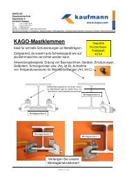
3. <strong>Installation</strong> of cable fastening clamps<br />
7<br />
Fastening clamps are<br />
basically mounted in<br />
the same way as contact<br />
clamps (see chapter<br />
2)!<br />
To protect the pipe from damage – caused by tamping or other track<br />
maintenance machines –, mount it next to the sleeper as close as<br />
possible, as shown in the pictures.
4. Clamp removal of contact and fastening clamps<br />
8<br />
Contact spring:<br />
For type E4, remove the<br />
spring before detaching the<br />
clamp from the rail! Using<br />
gentle blows on the notches<br />
(fig. I) or the small area at the<br />
top of the contact spring, you<br />
can free it and slide it out.<br />
Please refer chapter 6.2!<br />
For type E2/E3 we recommend<br />
the opposite procedure.<br />
Please refer chapter 6.1!<br />
Clamp:<br />
Detach the clamp from the rail<br />
with a well-aimed hammer<br />
blow from above on the tip of the clamp (fig. II). Because the<br />
mounted clamp is under mechanical pressure, it is important that<br />
you ensure nobody is standing behind or in front of you during the<br />
process. Protect yourself by placing the sole of your shoe in the direction<br />
of the clamp head.<br />
Caution:<br />
Never strike the side of the clamp (fig. III), because this will impair<br />
its spring pressure and ruin it for further use as a contact clamp!
5.1. Cable installation for types E2 and E3<br />
Some connecting possibilities:<br />
Before mounting the wire or the<br />
cable, first remove the contact<br />
spring. This is done most easily<br />
by gently hammering on the<br />
front end of the contact spring,<br />
before the clamp is mounted to<br />
the rail (ill. left). Otherwise<br />
knock the spring out by wellaimed<br />
hits with the pointed end<br />
of the hammer (ill. right).<br />
Typ E2<br />
Groove Wire type / Cable cross-section<br />
7 mm Wire ø 7 mm<br />
6 mm Wire ø 6 mm or flexible cable 25 mm 2 / 35 mm 2<br />
10 mm Flexible cable 50 mm 2 or highly flexible 70 mm 2<br />
3 mm Wire ø 3 mm or flexible cable 4 mm 2<br />
Typ E3<br />
Groove Wire type/ Cable cross-section<br />
8 mm Wire ø 8 mm or flexible Cable 50 mm 2 highly flexible<br />
5 mm Wire ø 5 mm or flexible Cable 16 mm 2<br />
10 mm Flexible cable 50 mm 2 or highly flexible 70 mm 2<br />
3 mm Wire ø 3 mm or flexible cable 4 mm 2<br />
Before use please check if wire/cable fits and in which groove!<br />
Lay the bright cable or wire into the correct<br />
groove (I) and push the contact spring through<br />
the rear slot (II) over the cable into the front<br />
slot.<br />
Now hammer (I)<br />
the contact spring<br />
onto the clamp head up to the stop (II).<br />
Due to the pressure of the spring, an excellent<br />
electrical contact is guaranteed!<br />
Caution: Use only one cable at a time!<br />
9
5.2. Cable installation for type E4<br />
Before fixing the cable, the contact spring<br />
must be removed. This is done most easily<br />
when the clamp is still mounted on the<br />
rail, namely with gentle taps on the notches<br />
(ill. left) or the small area at the top<br />
of the contact spring (in the picture between<br />
forefinger and thumb). Simultaneously<br />
slide the spring out of the clamp.<br />
Some connecting possibilities:<br />
Groove Cable type Cross-section<br />
5-6 mm Stranded wire 15 mm 2<br />
7-10 mm Flexible cable 35/50/70 mm 2<br />
11-16 mm Flexible cable 120 mm 2<br />
17-21 mm Flexible cable 240 mm 2<br />
Afterwards lay the stripped cable into the<br />
correct groove (I) and slide the contact<br />
spring from behind into the clamp head<br />
(II). The cable must be slightly clamped by<br />
the spring pressure, and the contact<br />
spring must hold its position by itself.<br />
Before use please check if cable fits and in which groove!<br />
Now hammer (I) the contact spring<br />
onto the clamp head up to the stop (II).<br />
The notches hold it in position. Due to<br />
the pressure of the spring, an excellent<br />
electrical contact is guaranteed.<br />
Caution: Not appropriate for stiff<br />
cables!<br />
Use only one cable at a time!<br />
10
5.3. Cable installation for type E5<br />
Connecting type E5 has been developed as a complement to type<br />
E4 and is delivered with the loose clamping counterpart (I), the horizontal<br />
adjustment part (II), a locking plate (III) and a screw M16x50<br />
(IV).<br />
IV<br />
III<br />
II<br />
I<br />
In both grooves, steel, bronze and copper wires and cables with diameters<br />
between 9 and 14 mm can be clamped. This corresponds<br />
with cable cross-sections of ca. 50–120 mm 2 according to the conductor<br />
structure.<br />
When using big cross-sections, it is recommendable on the one<br />
hand to leave out the washer, so that the screw can be screwed in<br />
deeply enough, on the other hand both grooves should be occupied<br />
with the cable to guarantee an optimal contact pressure.<br />
Caution: To avoid loose cable connections, make absolutely<br />
sure new locking plates are correctly mounted for every renewed<br />
cable mounting! For mounting tips please refer to the end<br />
of chapter 5.4. at the bottom of the next page.<br />
11
5.4. Cable installation for types GI and EI<br />
Place the cable lug (I), the locking<br />
plate (II) and the bolt (III) on the<br />
clamp.<br />
Type GI: Suitable for cable lugs up to 150mm 2 .<br />
Type EI: Suitable for cable lugs up to 240mm 2 .<br />
Afterwards tighten the bolt according<br />
to the dimension of the thread:<br />
Thread Tightening torque in Nm<br />
M8 15<br />
M10 30<br />
M12 50<br />
M16 120<br />
To prevent the bolt from loosening even through massive vibrations,<br />
hammer the longer flap of the locking<br />
plate down towards the side of<br />
the clamp (ill. right) and the<br />
shorter flap up towards the<br />
bolt (ill. left).<br />
Caution: To avoid loose cable connections,<br />
make absolutely sure that new locking plates are correctly mounted<br />
for every renewed cable mounting!<br />
12
5.5. Cable installation for type EA<br />
Place the cable lug and the re-usable self-locking nut on the clamp.<br />
Then tighten the nut according to the dimension of the stud:<br />
Stud Tightening torque in Nm<br />
M8 15<br />
M10 30<br />
M12 50<br />
M16 120<br />
M20 240<br />
Type EA: Suitable for cable lugs up to 240 mm 2 .<br />
Caution: To avoid loose cable connections, please ensure that you<br />
always apply re-usable or new locknuts for every renewed cable<br />
mounting!<br />
13
5.6. Cable laying of railbonds<br />
To protect the cable from damage – caused by tamping or other<br />
track maintenance machines –, lay it as close as possible to rails<br />
and sleepers, as shown in the pictures.<br />
14
6.1. Why testing of rail contact clamps?<br />
KAGO rail contact clamps<br />
were not only developed for<br />
one-way use. On the contrary:<br />
If they are always<br />
mounted correctly, KAGO<br />
clamps have a very long lifetime<br />
and can be used again<br />
and again! Of course their<br />
clamping pressure could<br />
slightly decrease with every<br />
repeated fastening, so that a<br />
testing of the clamping pressure<br />
is recommendable before<br />
using KAGO clamps<br />
again! After all they have an<br />
important role to play in railway<br />
safety, which means<br />
they must be absolutely dependable!<br />
The testing must be done<br />
with the KAGO testing gauge:<br />
If the clamp holds on the<br />
precision pin, the function is<br />
guaranteed (fig. a). If it falls<br />
through, it is no longer usable<br />
(fig. b).<br />
When it comes to railbonds,<br />
do not forget to take the opportunity<br />
to also check the condition of the cables!<br />
Caution: The existing testing gauge loses its validity for clamps with<br />
the lot marking C26... (see clamp bottom). We look forward to offering<br />
you a new testing gauge for C26... clamps!<br />
15
6.2. Testing instructions for KAGO clamps<br />
(1) Tighten the testing gauge in a vice.<br />
(2) Place the clamp onto the precision pin of the testing gauge<br />
from above.<br />
(3a) Good: Clamp holds on the pin, i.e. it can be re-used.<br />
(3b) Bad: Clamp falls through, i.e. it is no longer usable.<br />
16
6.3. Groove cleaning and spring checking<br />
(only for connecting types E2, E3 & E4)<br />
E2<br />
E3<br />
E4<br />
17<br />
Low voltage connections<br />
(1,5-12 Volt)<br />
are only guaranteed<br />
as long as each<br />
KAGO clamp is<br />
tested after use with<br />
the gauge and if<br />
dirty grooves have<br />
been cleaned by<br />
means of a steel<br />
brush and a liquid<br />
cleaner (like paraffin)<br />
if required!<br />
Contact springs can<br />
break when<br />
mounted carelessly<br />
(too hard hits, canting,<br />
etc.)! They must<br />
be treated – unlike<br />
the clamp itself – as<br />
wearing parts that<br />
have to be replaced<br />
when signs of wear<br />
and tear like deformations,<br />
cracks, etc.<br />
appear!
The policy of KAGO AG is one of continuous development. The<br />
company therefore reserves the right to change specifications and<br />
introduce design improvements at any time and without notice.<br />
For more detailled information please refer to our „KAGO Clamp<br />
Directory“!<br />
This installation manual must be strictly obeyed and no KAGO<br />
clamps must be modified mechanically or by welding,<br />
otherwise any product liability will be rejected.<br />
The latest update of this booklet can be found on<br />
http://www.kago.com/pdf/e_62_mi.pdf<br />
Copyright by KAGO AG.<br />
All rights reserved.<br />
Version 19.11.2012<br />
20