IMC 0609, App A - NRC
IMC 0609, App A - NRC
IMC 0609, App A - NRC

You also want an ePaper? Increase the reach of your titles
YUMPU automatically turns print PDFs into web optimized ePapers that Google loves.
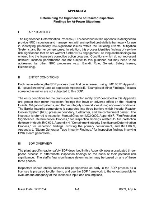
I APPLICABILITY<br />
APPENDIX A<br />
Determining the Significance of Reactor Inspection<br />
Findings for At-Power Situations<br />
The Significance Determination Process (SDP) described in this <strong>App</strong>endix is designed to<br />
provide <strong>NRC</strong> inspectors and management with a simplified probabilistic framework for use<br />
in identifying potentially risk-significant issues within the Initiating Events, Mitigation<br />
Systems, and Barrier cornerstones. In addition, this process identifies findings of very low<br />
risk significance that do not warrant further <strong>NRC</strong> engagement, as long as the findings are<br />
entered into the licensee’s corrective action program. Conditions which do not represent<br />
deficient licensee performance are not subject to this guidance but may need to be<br />
addressed by other <strong>NRC</strong> processes (e.g., Backfit Rule, Generic Safety Issues,<br />
Rulemaking).<br />
II ENTRY CONDITIONS<br />
Each issue entering the SDP process must first be screened using <strong>IMC</strong> 0612, <strong>App</strong>endix<br />
B, “Issue Screening”, and as applicable <strong>App</strong>endix E, “Examples of Minor Findings.” Issues<br />
screened as minor are not subjected to this SDP.<br />
The entry conditions for the plant-specific reactor safety SDP described in this <strong>App</strong>endix<br />
are greater than minor inspection findings that have an adverse effect on the Initiating<br />
Events, Mitigation Systems, and Barrier Integrity cornerstones during at-power conditions.<br />
The Barrier Integrity cornerstone is separated into three barriers which include: Reactor<br />
Coolant System (RCS) pressure boundary, fuel barrier, and the containment barrier. The<br />
inspector is referred to Inspection Manual Chapter (<strong>IMC</strong>) <strong>0609</strong>, <strong>App</strong>endix F, “Fire Protection<br />
Significance Determination Process,“ for inspection findings related to fire protection<br />
defense-in-depth, <strong>IMC</strong> 609, <strong>App</strong>endix H, “Containment Integrity Significance Determination<br />
Process,” for inspection findings involving the primary containment, and <strong>IMC</strong> <strong>0609</strong>,<br />
<strong>App</strong>endix J, “Steam Generator Tube Integrity Findings,” for inspection findings involving<br />
PWR steam generators.<br />
III SDP OVERVIEW<br />
The plant-specific reactor safety SDP described in this <strong>App</strong>endix uses a graduated threephase<br />
process to differentiate inspection findings on the basis of their potential risk<br />
significance. The staff’s final significance determination may be based on any of these<br />
three phases.<br />
Inspectors should obtain licensee risk perspectives as early in the SDP process as a<br />
licensee is prepared to offer them, and use the SDP framework to the extent possible to<br />
evaluate the adequacy of the licensee’s input and assumptions.<br />
Issue Date: 12/01/04 A-1 <strong>0609</strong>, <strong>App</strong> A
Phase 1 - Characterization and Initial Screening of Findings<br />
Phase 1 is used to characterize the important attributes of the inspection<br />
finding and to initially screen the finding to identify those with very lowsignificance,<br />
which can be dispositioned by the licensee’s corrective action<br />
program.<br />
The Phase 1 Worksheet is applicable for all plant types and is included in this<br />
<strong>App</strong>endix.<br />
Phase 1 is intended to be accomplished by the inspection staff, with the<br />
assistance of a Senior Reactor Analyst (SRA), if needed.<br />
Phase 2 - Risk Significance Estimation and Justification Using the Site Specific<br />
Risk-Informed Inspection Notebook :<br />
Phase 2 is used to develop a plant specific estimate of the risk significance<br />
of an inspection finding and to develop the basis for that determination.<br />
The Phase 2 Worksheets are plant-specific in order to account for variations<br />
in available mitigation equipment and other plant-specific attributes. The<br />
examples of Phase 2 Worksheets used in this <strong>App</strong>endix are identified as<br />
Table 3.XX. When conducting a Phase 2 analysis, the actual data contained<br />
in the various parts of Table 3 in the site specific risk-informed inspection<br />
notebook must be used. The risk-informed inspection notebooks can be<br />
found on the <strong>NRC</strong> internal web-page by accessing “Risk Informed Regulatory<br />
Activities” on the NRR Home Page. The notebooks are not publicly available.<br />
The Phase 2 is intended to be accomplished by the inspection staff, with the<br />
assistance of an SRA, if needed. SRAs should review all completed Phase<br />
2 assessments to ensure the results are consistent with the Phase 2<br />
guidance.<br />
The results of the Phase 2 analysis may be used as the final significance<br />
determination.<br />
Phase 3 - Risk Significance Estimation Using Any Risk Basis That Departs from<br />
the Phase 1 or 2 Process:<br />
Phase 3 is used to address those situations that depart from the guidance<br />
provided for Phase 1 or Phase 2. A Phase 3 analysis need be no more<br />
detailed than an adjustment to the Phase 2 result that is not explicitly<br />
permitted by this <strong>App</strong>endix.<br />
If the Phase 2 SDP Worksheets do not clearly address the inspection finding<br />
of concern (e.g., internal flooding, etc.), then a Phase 3 analysis of the<br />
inspection finding should be performed to characterize the significance of the<br />
finding.<br />
<strong>0609</strong>, <strong>App</strong> A A-2 Issue Date: 12/01/04
Phase 3 is intended to be performed using appropriate PRA techniques and<br />
rely on the expertise of an SRA or risk analyst using the best available<br />
information that is accessible or can be determined within the SDP timeliness<br />
goal.<br />
IV TREATMENT OF CONCURRENT MULTIPLE EQUIPMENT OR FUNCTIONAL<br />
DEGRADATIONS<br />
Concurrent multiple equipment or functional degradations are evaluated based on their<br />
cause. If the concurrent multiple equipment or functional degradations resulted from a<br />
common cause (e.g., a single inadequate maintenance procedure that directly resulted in<br />
deficient maintenance being performed on multiple components), then a single inspection<br />
finding is written. The significance characterization is determined using a reactor safety<br />
Phase 3 SDP, is based on the time periods during which the degradations existed, and<br />
reflects the total increase in core damage frequency (CDF).<br />
If multiple cornerstones were affected, the single finding will be assigned to the cornerstone<br />
which best reflects the dominant risk influences. The justification for the existence of a<br />
common cause must be a stronger causal relationship than poor management or crosscutting<br />
programs (e.g., an inadequate problem identification and resolution program is an<br />
inadequate basis to justify a common cause finding).<br />
If independent causes are determined to have resulted in multiple equipment or functional<br />
degradations, then separate inspection findings are written. The findings are individually<br />
characterized for significance, assuming none of the other independent findings existed.<br />
This is necessary to account for the probabilistic independence of the findings.<br />
In all cases, the risk of concurrent multiple equipment or functional degradations and the<br />
staff’s basis for treating these effects as either having a common cause or being<br />
independent should be documented in an inspection report or other appropriate public<br />
correspondence.<br />
V NON-APPLICABILITY OF SDP FOR <strong>NRC</strong> DETERMINATION OF RISK<br />
SIGNIFICANCE OF EVENTS<br />
The risk significance of actual reactor events caused or complicated by equipment<br />
malfunction or operator error must be assessed by <strong>NRC</strong> risk analysts in accordance with<br />
MD 8.3, “<strong>NRC</strong> Incident Investigation Program.” Although this SDP may provide useful risk<br />
insights to inspectors for event response or followup, it was not designed for that purpose.<br />
Because the SDP is used to estimate the risk significance of licensee performance<br />
deficiencies, including those that manifest themselves during events, the performance<br />
deficiencies associated with an actual reactor event should be dispositioned using the SDP<br />
in the same fashion as all other performance deficiencies.<br />
Issue Date: 12/01/04 A-3 <strong>0609</strong>, <strong>App</strong> A
VI RELATIONSHIP OF THE SDP TO THE RISK-INFORMED PERFORMANCE<br />
INDICATORS<br />
The <strong>NRC</strong> Reactor Oversight Process (as defined in <strong>IMC</strong> 2515) evaluates licensee<br />
performance using a combination of Performance Indicators (PIs) and inspections.<br />
Thresholds have been established for the PIs, which, if exceeded, may prompt additional<br />
<strong>NRC</strong> actions to focus both licensee and Agency’s attention on areas where there is a<br />
potential decline in licensee performance.<br />
The white-yellow and yellow-red thresholds for the initiating events and mitigating systems<br />
performance indicators were risk-informed using the same “scale” as the SDP described<br />
in this appendix. The green-white thresholds were set low enough to identify performance<br />
outliers. As a result, licensee performance is assessed by comparing and “adding” the<br />
contributions of both performance indicators and inspection findings in the Action Matrix.<br />
END<br />
Attachment 1 - User Guidance for Significance Determination of Reactor Inspection<br />
Findings for At-Power Situations<br />
Attachment 2 - Site Specific Risk-Informed Inspection Notebook Usage Rules<br />
<strong>0609</strong>, <strong>App</strong> A A-4 Issue Date: 12/01/04
APPENDIX A<br />
ATTACHMENT 1<br />
User Guidance<br />
for Determining the Significance of Reactor Inspection Findings<br />
for At-Power Situations<br />
Phase 1 - Characterization and Initial Screening of Findings<br />
Step 1.1: Characterize the inspection finding and describe the assumed impact.<br />
(1) Record the performance deficiency and factually describe known<br />
observations associated with the deficiency on page 1 of the Phase 1<br />
Screening Worksheet.<br />
(2) Describe the known or assumed impact on affected plant safety functions<br />
(e.g., high/low pressure injection, containment heat removal, power<br />
conversion system, etc.) Note that the safety functions affected must be<br />
those identified in the Site Specific Risk-Informed Inspection Notebooks,<br />
when applicable. Do not include hypothetical conditions (e.g., single failure<br />
criteria) or speculate on the “worst case” potential degradation as an input to<br />
an official SDP result. However, a bounding determination of significance<br />
may be made by assuming a worst-case condition. For example, assume<br />
complete loss of function, even if unsupported by the facts known at that<br />
time. However, if a bounding determination results in a greater than green<br />
characterization, greater factual detail will be necessary to complete the<br />
official SDP.<br />
CAUTION: The SDP is used to estimate the increase in CDF<br />
due only to deficient licensee performance. Therefore, the SDP<br />
evaluation should not include equipment unavailability due to<br />
planned maintenance and testing. The impact of this equipment<br />
not being available for mitigation purposes is included in the<br />
baseline CDF for each plant.<br />
Step 1.2: Perform an initial screening of the inspection finding.<br />
(1) Use the decision logic on pages 4 and 5 of the Phase 1 Screening Worksheet<br />
to determine if the issue can be characterized as Green. Note that the<br />
examples provided in the worksheet are not all inclusive.<br />
(2) If the finding screens as Green, then document in accordance with <strong>IMC</strong> 0612.<br />
(3) If the finding screens as other than Green, perform a Phase 2 analysis.<br />
Issue Date: 12/01/04 A1-1 <strong>0609</strong>, <strong>App</strong> A, Att 1
Phase 2 - Risk Significance Estimation and Justification Using the Site Specific<br />
Risk-Informed Inspection Notebook<br />
The Phase 2 process uses the following tables found in the Site Specific Risk-informed<br />
Inspection Notebooks. The plant specific notebooks can be found on the <strong>NRC</strong> internal<br />
web-page by accessing “Risk Informed Regulatory Activities” on the NRR Home Page. The<br />
tables presented in this <strong>App</strong>endix are generic for the purpose of illustration.<br />
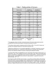
Table 1 “Categories of Initiating Events for XXX Plant”<br />
Table 2 “Initiators and System Dependency for XXX Plant”<br />
Table 3 “SDP Worksheets for XXX Plant”<br />
Table 4 “Remaining Mitigation Capability Credit”<br />
Table 5 “Counting Rule Worksheet”<br />
Step 2.1: Select the initiating event scenarios.<br />
On Table 2, “Initiators and System Dependency for XXX Plant,” in the plant specific<br />
notebook, locate the equipment or safety function that was assumed to be affected<br />
by the inspection finding. Identify the initiating event scenarios that must be<br />
evaluated using the plant specific worksheets. (See Table 2 in this attachment for<br />
an example.)<br />
Step 2.2: Estimate the Initiating Event Likelihood.<br />
(1) On Table 1, “Categories of Initiating Events for XXX Plant,” locate the<br />
exposure time associated with the finding (i.e., > 30 days, between 3 and 30<br />
days, or < 3 days). If the inception of the condition is unknown, go to Usage<br />
Rule 1.1 of Attachment 2, “Site Specific Risk-Informed Inspection Notebook<br />
Usage Rules,” of this <strong>App</strong>endix to determine the appropriate exposure time.<br />
(2) Determine the Initiating Event Likelihood (i.e., 1 through 8) for each of the<br />
initiating events identified in Step 2.1.<br />
(3) Go to Attachment 2 and review the information contained in Phase 1<br />
Worksheet to determine if the finding increases the likelihood of each<br />
initiating event identified in Step 2.1.<br />
(4) If the finding increases the likelihood of an initiating event, increase the<br />
Initiating Event Likelihood (IEL) value in accordance with the SDP usage<br />
rules in Attachment 2.<br />
(5) Enter the IEL value in the IEL column on the applicable notebook worksheet.<br />
(See Table 3.XX “SDP Worksheet for Generic BWR,” contained in this<br />
<strong>App</strong>endix.)<br />
Step 2.3: Estimate the Remaining Mitigation Capability in accordance with the<br />
SDP usage rules in Attachment 2.<br />
<strong>0609</strong>, <strong>App</strong> A, Att 1 A1-2 Issue Date: 12/01/04
(1) For each of the inspection scenarios identified in Step 2.1, determine which<br />
safety functions are affected by the finding.<br />
(2) Circle the affected safety functions on each worksheet identified in Step 2.1.<br />
(3) If the inspection finding increases the likelihood of an initiating event, circle<br />
the initiating event for each of the sequences on the worksheet for that<br />
particular initiating event.<br />
(4) Evaluate the unaffected equipment for each safety function affected by the<br />
finding. Using Table 4, “Remaining Mitigation Capability Credit,” determine<br />
the remaining mitigation capability credit for each of these functions. The<br />
remaining mitigation capability credit assigned may or may not be reduced<br />
as a result of the inspection finding. Unaffected safety functions will retain<br />
their assigned full mitigation capability credit.<br />
(5) Determine if an operator could recover the unavailable equipment or function<br />
in time to mitigate the assumed initiating event. Credit for recovery should<br />
be given only if the following criteria are satisfied:<br />
(a) sufficient time is available;<br />
(b) environmental conditions allow access, where needed;<br />
(c) procedures describing the appropriate operator actions exist;<br />
(d) training is conducted on the existing procedures under similar<br />
conditions;<br />
(e) any equipment needed to perform these actions is available and ready<br />
for use.<br />
If recovery credit is appropriate, enter a value of 1 in the Recovery of Failed<br />
Train column of the applicable inspection notebook worksheets.<br />
Step 2.4: Estimate the risk significance of the inspection finding.<br />
(1) Determine the Sequence Risk Significance for each of the sequences circled<br />
in Step 2.3 (1), using the following formula:<br />
Sequence Risk Significance = (Initiating Event Likelihood + Remaining Mitigation<br />
Capability Credit + Recovery Credit)<br />
(2) Complete Table 5, “Counting Rule Worksheet.” The result is the Risk<br />
Significance (i.e., Green, White, Yellow, or Red) of the inspection finding<br />
based on the internal initiating events that lead to core damage.<br />
Step 2.5: Screen for the potential risk contribution due to external initiating<br />
events.<br />
Issue Date: 12/01/04 A1-3 <strong>0609</strong>, <strong>App</strong> A, Att 1
The plant-specific SDP Phase 2 Worksheets do not currently include initiating events<br />
related to fire, flooding, severe weather, seismic, or other initiating events that are<br />
considered by the licensee’s IPEEE analysis. Therefore, the increase in risk of the<br />
inspection finding due to these external initiators is not accounted for in the reactor safety<br />
Phase 2 SDP result. Because the increase in risk due to external initiators may increase<br />
the risk significance characterization of the inspection finding, the impact of external<br />
initiators should be evaluated by a SRA or other <strong>NRC</strong> risk analyst. Experience with using<br />
the Site Specific Risk-Informed Inspection Notebooks has indicated that accounting for<br />
external initiators could result in increasing the risk significance attributed to an<br />
inspection finding by as much as one order of magnitude. Therefore, if the Phase 2 SDP<br />
result for an inspection finding represents an increase in risk of greater than or equal to<br />
1E-7 per year (Risk Significance Estimation of 7 or less), then an SRA or other <strong>NRC</strong> risk<br />
analyst should perform a Phase 3 analysis to estimate the increase in risk due to external<br />
initiators. This evaluation may be qualitative or quantitative in nature. Qualitative<br />
evaluations of external events should, as a minimum, provide the logic and basis for the<br />
conclusion and should reference all of the documents reviewed.<br />
Step 2.6 - Screen for the Potential Risk Contribution Due to Large Early Release<br />
Frequency (LERF).<br />
If the total ªCDF from the Phase 2 Worksheets (i.e., sum of all sequences) is less than<br />
1E-7 per year, then the finding is not significant from a LERF perspective and no further<br />
evaluation is necessary. However, if the total ªCDF is greater than or equal to 1E-7 then<br />
the finding must be screened for its potential risk contribution to LERF using <strong>IMC</strong> <strong>0609</strong>,<br />
<strong>App</strong>endix H.<br />
Phase 3 - Risk Significance Estimation Using Any Risk Basis That Departs from the<br />
Phase 1 or 2 Process:<br />
If necessary, Phase 3 will refine or modify, with sufficient justification, the earlier screening<br />
results from Phases 1 and 2. In addition, Phase 3 will address findings that cannot be<br />
evaluated using the Phase 2 process. Phase 3 analysis will utilize appropriate PRA<br />
techniques and rely on the expertise of <strong>NRC</strong> risk analysts using the best available<br />
information that is accessible or can be determined within the SDP timeliness goal.<br />
<strong>0609</strong>, <strong>App</strong> A, Att 1 A1-4 Issue Date: 12/01/04
Human Reliability Analysis (HRA) Model 1<br />
Use the Accident Sequence Precursor (ASP) Human Error Worksheets to derive the<br />
applicable human error probabilities (HEPs) in SDP Phase 3 evaluations. If the licensee’s<br />
PRA model is used as the basis for the Phase 3 evaluation and if there are no concerns<br />
with the licensee’s HRA method (e.g., the concerns with the licensee’s HRA method<br />
identified during the staff’s review of the licensee’s IPE submittal, if any, have been<br />
corrected), then use the licensee’s HRA method. The adequacy of any influential<br />
assumptions used in any HEP analysis must always be determined and documented.<br />
Initiating Event Frequency<br />
NUREG/CR-5750, "Rates of Initiating Events at U.S. Nuclear Power Plants: 1987 - 1995,"<br />
provides generic frequency estimates for the occurrence of initiating events in U.S. nuclear<br />
plants. For SDP Phase 3 evaluations, the frequency estimates of LOCA events as listed<br />
in NUREG/CR-5750 may be used. However, the initiating event frequency estimates used<br />
in the licensee's PRA model should be used if these estimates are more conservative (i.e.,<br />
higher) than those listed in NUREG/CR-5750.<br />
If relevant factual evidence of plant conditions or characteristics are known and could<br />
increase these frequency estimates, then the Probabilistic Safety Assessment Branch<br />
(SPSB)/NRR should be consulted to determine whether the evidence and the associated<br />
degree of uncertainty provides reasonable confidence that the frequency estimates do not<br />
significantly alter the significance characterization of the inspection finding.<br />
Documentation<br />
Each finding evaluated through the SDP must be given a color characterizing its<br />
significance. In addition, each inspection finding must be justified with sufficient detail to<br />
allow a knowledgeable reader to reconstruct the decision logic used to arrive at the final<br />
color. Further guidance on inspection report documentation is provided in <strong>IMC</strong> 0612.<br />
1 It is recognized that several HRA methods are available to quantify human error<br />
probabilities (HEPs) for use in probabilistic risk analysis (PRA) models. However, there is no<br />
general agreement among PRA experts as to which HRA method should be used for HEP<br />
quantification.<br />
Issue Date: 12/01/04 A1-5 <strong>0609</strong>, <strong>App</strong> A, Att 1
SDP PHASE 1 SCREENING WORKSHEET FOR INITIATING EVENTS, MITIGATION<br />
SYSTEMS, AND BARRIERS CORNERSTONES<br />
Reference/Title (LER #, Inspection Report #, etc):<br />
Performance Deficiency (concise statement clearly stating deficient licensee performance):<br />
Factual Description of Condition (statement of facts known about the condition that<br />
resulted from the performance deficiency, without hypothetical failures included):<br />
System(s)/Train(s) Degraded by Condition:<br />
Licensing Basis Function of System(s)/Train(s):<br />
Other Safety Function of System(s)/Train(s):<br />
Maintenance Rule Category (check one):<br />
____ risk-significant _____non risk-significant<br />
Time condition existed or is assumed to have existed:<br />
Page 1 of 5<br />
<strong>0609</strong>, <strong>App</strong> A, Att 1 A1-6 Issue Date: 12/01/04
CORNERSTONES AND FUNCTIONS DEGRADED AS A RESULT OF DEFICIENCY<br />
(U) Check the appropriate boxes<br />
INITIATING EVENTS<br />
CORNERSTONE<br />
’ Primary System LOCA initiator<br />
contributor - (e.g., RCS leakage<br />
from pressurizer heater sleeves,<br />
RPV piping penetrations, CRDM<br />
nozzles, PORVs, SRVs, ISLOCA<br />
issues, etc.)<br />
’ Transient initiator contributor<br />
(e.g., reactor/turbine trip, loss of<br />
offsite power, loss of service<br />
water, main steam/feedwater<br />
piping degradations, etc.)<br />
’ Fire initiator contributor (e.g.,<br />
transient loadings and<br />
combustibles, hotwork)<br />
’ Internal/external flooding initiator<br />
contributor<br />
MITIGATION SYSTEMS<br />
CORNERSTONE<br />
” Core Decay Heat Removal<br />
Degraded<br />
” Short Term Heat Removal<br />
Degraded<br />
’ Primary (e.g., Safety Inj,<br />
[main feedwater, HPCI,<br />
and RCIC - BWR only] )<br />
High Pressure<br />
Low Pressure<br />
” Secondary - PWR only<br />
(e.g. AFW, main<br />
feedwater, ADVs)<br />
” Long Term Heat Removal<br />
Degraded (e.g., ECCS sump<br />
recirculation, suppression<br />
pool)<br />
” Reactivity Control Degraded<br />
” Seismic/Fire/Flood/Severe<br />
Weather Protection Degraded<br />
BARRIERS CORNERSTONE<br />
” RCS Boundary as a mitigator<br />
following plant upset (e.g.,<br />
pressurized thermal shock).<br />
” Containment Barrier Degraded<br />
” Reactor Containment<br />
Degraded<br />
Actual Breach or<br />
Bypass<br />
Heat Removal,<br />
Hydrogen or Pressure<br />
Control Degraded<br />
” Control Room, Aux<br />
Bldg/Reactor Bldg, or Spent<br />
Fuel Bldg Barrier Degraded<br />
” Fuel Cladding Barrier Degraded<br />
Page 2 of 5<br />
Issue Date: 12/01/04 A1-7 <strong>0609</strong>, <strong>App</strong> A, Att 1
SDP PHASE 1 SCREENING WORKSHEET FOR IE, MS, and B CORNERSTONES<br />
Check the appropriate boxes U<br />
IF the finding is assumed to degrade:<br />
1. fire protection defense-in-depth strategies involving: detection, suppression (equipment for both<br />
manual and automatic), barriers, fire prevention and administrative controls, and post fire safe<br />
shutdown systems, THEN STOP. Go to <strong>IMC</strong> <strong>0609</strong>, <strong>App</strong>endix F. Issues related to performance<br />
of the fire brigade are not included in <strong>App</strong>endix F and require <strong>NRC</strong> management review.<br />
2. steam generator tube integrity, THEN STOP. Go to <strong>IMC</strong> <strong>0609</strong>, <strong>App</strong>endix J.<br />
3. the safety of an operating reactor, THEN IDENTIFY the degraded cornerstone(s):<br />
9 Initiating Event<br />
9 Mitigation Systems<br />
9 RCS Barrier (e.g., PTS issues)<br />
9 Fuel Barrier<br />
9 Containment Barriers<br />
IF TWO OR MORE of the above cornerstones are degraded ý THEN STOP. Go to Phase 2.<br />
IF ONLY ONE of the above cornerstones is degraded, THEN CONTINUE in the appropriate column<br />
on page 4 of 5 of this worksheet.<br />
NOTE: When assessing the significance of a finding affecting multiple cornerstones, the finding<br />
should be assigned to the cornerstone that best reflects the dominant risk of the finding.<br />
Page 3 of 5<br />
<strong>0609</strong>, <strong>App</strong> A, Att 1 A1-8 Issue Date: 12/01/04
Initiating Events Cornerstone<br />
LOCA Initiators<br />
1. Assuming worst case<br />
degradation, would the finding<br />
result in exceeding the Tech<br />
Spec limit for identified RCS<br />
leakage or could the finding<br />
have likely affected other<br />
mitigation systems resulting in<br />
a total loss of their safety<br />
function.<br />
9 If YES ýStop. Go to<br />
Phase 2.<br />
9 If NO, screen as Green.<br />
Transient Initiators<br />
1. Does the finding contribute to<br />
both the likelihood of a reactor<br />
trip AND the likelihood that<br />
mitigation equipment or<br />
functions will not be available?<br />
9 If YESýStop. Go to Phase 2.<br />
9 If NO, screen as Green.<br />
External Event Initiators<br />
1. Does the finding increase the<br />
likelihood of a fire or<br />
internal/external flood?<br />
9 If YES ý Use the IPEEE or<br />
other existing plant-specific<br />
analyses to identify core<br />
damage scenarios of concern<br />
and factors that increase the<br />
frequency. Provide this input<br />
for Phase 3 analysis.<br />
9 If NO, screen as Green.<br />
Mitigation Systems Cornerstone RCS Barrier or Fuel Containment Barriers<br />
1.<br />
9<br />
9<br />
Is the finding a design or<br />
qualification deficiency<br />
confirmed not to result in loss<br />
of function per GL 91-18 (rev<br />
1)?<br />
If YES, screen as Green.<br />
If NO, continue.<br />
Barrier<br />
1. RCS Barrier<br />
(e.g.,pressurized<br />
thermal shock<br />
issues)<br />
Stop. Go to Phase 3.<br />
2. Fuel Barrier<br />
Cornerstone<br />
1. Does the finding<br />
only represent a<br />
degradation of the<br />
radiological barrier<br />
function provided<br />
for the control<br />
room, or auxiliary<br />
building, or spent<br />
fuel pool, or SBGT<br />
|<br />
|<br />
|<br />
|<br />
|<br />
|<br />
|<br />
|<br />
|<br />
Screen as Green. system (BWR)?<br />
2. Does the finding represent a<br />
loss of system safety function?<br />
9 If YES ýStop. Go to Phase<br />
2.<br />
9 If NO, continue.<br />
3. Does the finding represent<br />
actual loss of safety function of<br />
a single Train, for > its Tech<br />
Spec Allowed Outage Time?<br />
9 If YES ý Stop. Go to Phase<br />
2.<br />
9 If NO, continue.<br />
4. Does the finding represent an<br />
actual loss of safety function of<br />
one or more non-Tech Spec<br />
Trains of equipment<br />
designated as risk-significant<br />
per 10CFR50.65, for >24 hrs?<br />
9 If YES ý Stop. Go to Phase<br />
2.<br />
9 If NO, continue.<br />
5. Does the finding screen as<br />
potentially risk significant due<br />
to a seismic, flooding, or<br />
severe weather initiating event,<br />
using the criteria on page 5 of<br />
this Worksheet?<br />
9 If YES ý Use the IPEEE or<br />
other existing plant-specific<br />
analyses to identify core<br />
damage scenarios of concern<br />
and provide this input for<br />
Phase 3 analysis.<br />
9 If NO, screen as Green.<br />
9 If YES ý screen<br />
as Green.<br />
9 If NO, continue.<br />
2. Does the finding<br />
represent a<br />
degradation of the<br />
barrier function of<br />
the control room<br />
against smoke or a<br />
toxic atmosphere?<br />
9 If YES ý Stop.<br />
Go to Phase 3.<br />
9 If NO, continue.<br />
3. Does the finding<br />
represent an actual<br />
open pathway in<br />
the physical<br />
integrity of reactor<br />
containment, or<br />
involve an actual<br />
reduction in<br />
defense-in-depth<br />
for the atmospheric<br />
pressure control or<br />
hydrogen control<br />
functions of the<br />
reactor<br />
containment?<br />
9 If YES ý Stop.<br />
Go to <strong>App</strong>endix H<br />
of <strong>IMC</strong> <strong>0609</strong>.<br />
9 If NO, screen as |<br />
Green. |<br />
Page 4 of 5<br />
Issue Date: 12/01/04 A1-9 <strong>0609</strong>, <strong>App</strong> A, Att 1
|<br />
SDP PHASE 1 SCREENING WORKSHEET FOR IE, MS, and B CORNERSTONES<br />
Seismic, Flooding, and Severe Weather Screening Criteria<br />
1. Does the finding involve the loss or degradation of equipment or function specifically designed<br />
to mitigate a seismic, flooding, or severe weather initiating event (e.g., seismic snubbers,<br />
flooding barriers, tornado doors)?<br />
9 If YES ý continue to question 2<br />
9 If NO ý skip to question 3<br />
2. If the equipment or safety function is assumed to be completely failed or unavailable, are ANY of<br />
the following three statements TRUE? The loss of this equipment or function by itself, during<br />
the external initiating event it was intended to mitigate<br />
a) would cause a plant trip or any of the Initiating Events used by Phase 2 for the plant in<br />
question;<br />
b) would degrade two or more Trains of a multi-train safety system or function;<br />
c) would degrade one or more Trains of a system that supports a safety system or function.<br />
9 If YES ýthe finding is potentially risk significant due to external initiating event core damage<br />
sequences - return to page 4 of this Worksheet<br />
9 If NO, screen as Green<br />
3. Does the finding involve the total loss of any safety function, identified by the licensee through a<br />
PRA, IPEEE, or similar analysis, that contributes to external event initiated core damage<br />
accident sequences (i.e., initiated by a seismic, flooding, or severe weather event)?<br />
9 If YES ýthe finding is potentially risk significant due to external initiating event core damage<br />
sequences - return to page 4 of this Worksheet<br />
9 If NO, screen as Green<br />
Result of Phase 1 screening process:<br />
9 Screen as Green 9 Go to Phase 2 9 Go to Phase 3<br />
Important Assumptions:<br />
Performed by: ______________________________________ Date: _______________<br />
Page 5 of 5<br />
<strong>0609</strong>, <strong>App</strong> A, Att 1 A1-10 Issue Date: 12/01/04
Row Initiating Event<br />
(IE) Frequency<br />
I<br />
II<br />
III<br />
IV<br />
V<br />
VI<br />
Table 1 - Generic Example - Categories for Initiating Events<br />
>1 per 1-10 yr C Reactor Trip (TRANS)<br />
C Loss of Power Conversion<br />
System (TPCS)<br />
1 per 10-10 2 yr C Loss of Offsite Power (LOOP)<br />
C Inadvertent or Stuck Open<br />
SRV (IORV) - (BWR)<br />
1 per 10 2 -10 3 yr C Steam Generator Tube<br />
Rupture (SGTR)<br />
C Loss of Component Cooling<br />
Water (LCCW)<br />
C Stuck open PORV/SRV<br />
(SORV) - (PWR)<br />
C Small LOCA including RCP<br />
seal failures - (PWR)<br />
C MSLB/MFLB<br />
1 per 10 3 -10 4 yr C Small LOCA (RCS rupture) -<br />
(BWR)<br />
C Med LOCA<br />
C loss of offsite power with loss<br />
of one AC bus (LEAC)<br />
1 per 10 4 -10 5 yr C Large LOCA<br />
C ATWS - (BWR)<br />
30<br />
days<br />
30-3<br />
days<br />
Table 2 - Generic BWR Example - Initiators and System Dependency<br />
Affected System Major Components Support Systems Initiating Event Scenarios<br />
Code Name<br />
ADS Reactor Vessel<br />
Pressure Control and<br />
Automatic<br />
Depressurization<br />
System<br />
PCS Power Conversion<br />
System<br />
RHR Residual Heat<br />
Removal<br />
5 relief Valves (ADS)<br />
& 8 safety valves<br />
3 reactor feed<br />
pumps, 4<br />
condensate pumps,4<br />
condensate booster<br />
pumps<br />
2 Loops, each with 2<br />
RHR pumps & 1<br />
RHR HX, MOVs<br />
IA/nitrogen, 125 V-DC All except LLOCA<br />
4160 V-AC, 125 V-DC, TBCCW, IA TRAN, IORV, SLOCA,<br />
ATWS<br />
4160 V-AC, 125 V-DC, 480V AC,<br />
RHRSW, Pump Room HVAC<br />
AC AC Power (non-EDG) 4160V AC, 480V AC 125V DC All<br />
DC DC Power 125V DC (2 batteries<br />
& 4 battery charger),<br />
250V DC (2 batteries<br />
& 3 battery charger)<br />
(shared between two<br />
units)<br />
EDG Emergency Diesel<br />
Generators<br />
1 dedicated EDG, 1<br />
shared EDG, & 1<br />
SBO DG<br />
RHRSW RHR Service Water 2 Loops, 2 pumpmotor<br />
set per loop<br />
<strong>0609</strong>, <strong>App</strong> A, Att 1 A1-12 Issue Date: 12/01/04<br />
All<br />
480V AC All<br />
125 V-DC, DGCW, EDG HVAC LOOP<br />
HVAC, 4160 V-AC, 480 V-AC, 125<br />
V-DC<br />
All
Affected System Major Components Support Systems Initiating Event Scenarios<br />
SW Service water 5 pumps in Unit 1/ 2<br />
Crib house; shared<br />
system supplying a<br />
common header<br />
TBCCW Turbine Building<br />
Closed Cooling Water<br />
System<br />
HPCI High Pressure<br />
Coolant Injection<br />
LPCS Low Pressure Core<br />
Spray<br />
RCIC Reactor Core Isolation<br />
Cooling<br />
FPS Fire Protection<br />
System<br />
CRD Control Rod Drive<br />
Hydraulic System<br />
2 pumps, 2 HXs, an<br />
expansion tank<br />
4160 V-AC, 125 V-DC, IA LOSW<br />
SW, IA, 4160 V-AC TRAN, TPCS, SLOCA,<br />
IORV, LOOP, ATWS<br />
1 TDP, MOV 125 V-DC, 250 V-DC, Room HVAC All except LLOCA, LOSW<br />
2 Trains or Loops; 1<br />
LPCS pump per train<br />
4160 V-AC, 480 V-AC, 125 V-DC,<br />
SW, Pump Room HVAC<br />
All except LOSW<br />
1 TDP, MOV 125 V-DC, Room HVAC All except LLOCA, MLOCA<br />
2 diesel fire pumps,<br />
MOV<br />
IA Instrument Air 2 compressors for<br />
each unit plus a<br />
shared compressor<br />
supplying both units<br />
SLC Standby Liquid<br />
Control<br />
APCV Augmented Primary<br />
Containment Vent<br />
120V AC, SW, 24V Nickelcadmium<br />
batteries<br />
2 MDP, MOV Non-emergency ESF AC Buses,<br />
TBCCW<br />
2 MDP, 2 explosive<br />
valves<br />
SW, 480V AC LOIA<br />
LOSW, LOIA<br />
480 V-AC, 125 V-DC ATWS<br />
Valves, Dampers Essential Service Bus, IA backed<br />
up by accumulators for each valve<br />
operator<br />
TRAN, TPCS, SLOCA,<br />
IORV, LOOP, ATWS<br />
Issue Date: 12/01/04 A1-13 <strong>0609</strong>, <strong>App</strong> A, Att 1<br />
All
Table 3.XX - SDP Worksheet for Generic BWR — Transients (Reactor Trip) (TRAN)<br />
Safety Functions Needed: Full Creditable Mitigation Capability for Each Safety Function:<br />
Power Conversion System (PCS) 1/3 Feedpumps and 1/4 condensate/condensate booster pumps (operator action = 3)<br />
High Pressure Injection (HPI) HPCI (1 ASD train) or RCIC (1 ASD train)<br />
Depressurization (DEP) 1/5 ADS valves (RVs) manually opened (operator action = 2)<br />
Low Pressure Injection (LPI) 1/4 RHR pumps in ½ trains in LPCI Mode (1 multi-train system) or ½ LPCS trains (1 multitrain<br />
system)<br />
Containment Heat Removal (CHR) 1/4 RHR pumps in ½ trains with heat exchangers and 1/4 RHRSW pumps in SPC (1 multitrain<br />
system)<br />
Containment Venting (CV) Venting through 8" drywell or wetwell APCV (operator action = 2)<br />
Late Inventory Makeup (LI) 2/2 CRD pumps (operator action = 2)<br />
Circle Affected Functions IEL Remaining Mitigation Capability Rating for<br />
Each Affected Sequence<br />
1 TRAN - PCS - CHR - CV (5, 9)<br />
1 + 3 + 3 + 2<br />
2 TRAN - PCS -CHR - LI (4, 8)<br />
1 + 3 + 3 + 2<br />
3 TRAN - PCS - HPI - DEP (11)<br />
1 + 3 + 2 + 2<br />
4 TRAN - PCS - HPI - LPI (10)<br />
1 + 3 + 2 + 6<br />
9<br />
9<br />
8<br />
12<br />
Identify any operator recovery actions that are credited to directly restore the degraded equipment or initiating event:<br />
Recovery<br />
of<br />
Failed<br />
Train<br />
Results<br />
If operator actions are required to credit placing mitigation equipment in service or for recovery actions, such credit should be given only if the following<br />
criteria are met: 1) sufficient time is available to implement these actions, 2) environmental conditions allow access where needed, 3) procedures<br />
exist, 4) training is conducted on the existing procedures under conditions similar to the scenario assumed, and 5) any equipment needed to complete<br />
these actions is available and available and ready for use.<br />
<strong>0609</strong>, <strong>App</strong> A, Att 1 A1-14 Issue Date: 12/01/04
Recovery of Failed Train<br />
Table 4 - Remaining Mitigation Capability Credit<br />
Type of Remaining Mitigation Capability Remaining<br />
Mitigation<br />
Capability Credit<br />
X = - log 10(failure<br />
prob)<br />
Operator action to recover failed equipment that is capable of being recovered<br />
after an initiating event occurs. Action may take place either in the control room<br />
or outside the control room and is assumed to have a failure probability of<br />
approximately 0.1 when credited as “Remaining Mitigation Capability.” Credit<br />
should be given only if the following criteria are satisfied: (1) sufficient time is<br />
available; (2) environmental conditions allow access, where needed; (3)<br />
procedures describing the appropriate operator actions exist; (4) training is<br />
conducted on the existing procedures under similar conditions; and (5) any<br />
equipment needed to perform these actions is available and ready for use.<br />
1 Automatic Steam-Driven (ASD) Train<br />
A collection of associated equipment that includes a single turbine-driven<br />
component to provide 100% of a specified safety function. The probability of such<br />
a train being unavailable due to failure, test, or maintenance is assumed to be<br />
approximately 0.1 when credited as “Remaining Mitigation Capability.”<br />
1 Train<br />
A collection of associated equipment (e.g., pumps, valves, breakers, etc.) that<br />
together can provide 100% of a specified safety function. The probability of this<br />
equipment being unavailable due to failure, test, or maintenance is approximately<br />
1E-2 when credited as “Remaining Mitigation Capability.”<br />
1 Multi-Train System<br />
A system comprised of two or more trains (as defined above) that are considered<br />
susceptible to common cause failure modes. The probability of this equipment<br />
being unavailable due to failure, test, or maintenance is approximately 1E-3 when<br />
credited as “Remaining Mitigation Capability,” regardless of how many trains<br />
comprise the system.<br />
2 Diverse Trains<br />
A system comprised of two trains (as defined above) that are not considered to be<br />
susceptible to common cause failure modes. The probability of this equipment<br />
being unavailable due to failure, test, or maintenance is approximately 1E-4 when<br />
credited as “Remaining Mitigation Capability.”<br />
Operator Action Credit<br />
Major actions performed by operators during accident scenarios (e.g., primary<br />
heat removal using bleed and feed, etc.). These actions are credited using three<br />
categories of human error probabilities (HEPs). These categories are Operator<br />
Action = 1 which represents a failure probability between 5E-2 and 0.5, Operator<br />
Action = 2 which represents a failure probability between 5E-3 and 5E-2, and<br />
Operator Action = 3 which represents a failure probability between 5E-4 and 5E-3.<br />
Issue Date: 12/01/04 A1-15 <strong>0609</strong>, <strong>App</strong> A, Att 1<br />
1<br />
1<br />
2<br />
3<br />
4 (=2+2)<br />
1, 2, or 3
Step Instructions<br />
Table 5 - Counting Rule Worksheet<br />
(1) Enter the number of sequences with a risk significance equal to 9. (1)<br />
(2) Divide the result of Step (1) by 3 and round down. (2)<br />
(3) Enter the number of sequences with a risk significance equal to 8. (3)<br />
(4) Add the result of Step (3) to the result of Step (2). (4)<br />
(5) Divide the result of Step (4) by 3 and round down. (5)<br />
(6) Enter the number of sequences with a risk significance equal to 7. (6)<br />
(7) Add the result of Step (6) to the result of Step (5). (7)<br />
(8) Divide the result of Step (7) by 3 and round down. (8)<br />
(9) Enter the number of sequences with a risk significance equal to 6. (9)<br />
(10) Add the result of Step (9) to the result of Step (8). (10)<br />
(11) Divide the result of Step (10) by 3 and round down. (11)<br />
(12) Enter the number of sequences with a risk significance equal to 5. (12)<br />
(13) Add the result of Step (12) to the result of Step (11). (13)<br />
(14) Divide the result of Step (13) by 3 and round down. (14)<br />
(15) Enter the number of sequences with a risk significance equal to 4. (15)<br />
(16) Add the result of Step (15) to the result of Step (14). (16)<br />
C If the result of Step 16 is greater than zero, then the risk significance of the inspection finding is of<br />
high safety significance (RED).<br />
C If the result of Step 13 is greater than zero, then the risk significance of the inspection finding is at<br />
least of substantial safety significance (YELLOW).<br />
C If the result of Step 10 is greater than zero, then the risk significance of the inspection finding is at<br />
least of low to moderate safety significance (WHITE).<br />
C If the result of Steps 10, 13, and 16 are zero, then the risk significance of the inspection finding is of<br />
very low safety significance (GREEN).<br />
Phase 2 Result: ~ GREEN ~ WHITE ~ YELLOW ~ RED<br />
<strong>0609</strong>, <strong>App</strong> A, Att 1 A1-16 Issue Date: 12/01/04
Table of Contents<br />
APPENDIX A<br />
ATTACHMENT 2<br />
Site Specific Risk-Informed Inspection Notebook Usage Rules<br />
1.0DETERMINING THE INITIATING EVENT LIKELIHOOD ........................ A2-2<br />
1.1Exposure Time ........................................................ A2-2<br />
1.2Inspection Finding (Not Involving a Support System) that Increases the Likelihood of an Initiating<br />
Event ................................................................ A2-2<br />
1.3Inspection Finding (Normally Cross-tied Support System) that Increases the Likelihood of an<br />
Initiating Event......................................................... A2-3<br />
1.4Inspection Finding (Normally Running Components of a Split Train Support System) that<br />
Increases the Likelihood of an Initiating Event and the Impact on Mitigating System Capability<br />
Can Be Explicitly Determined ............................................. A2-3<br />
1.5Inspection Finding (Normally Standby Components of a Split Train Support System) that<br />
Increases the Likelihood of an Initiating Event and the Impact on Mitigating System Capability<br />
Can Be Explicitly Determined ............................................. A2-4<br />
1.6Inspection Findings Involving Emergency Diesel Generators ..................... A2-4<br />
1.7Inspection Findings Involving Safety-Related Battery Chargers ................... A2-5<br />
2.0 DETERMINING REMAINING MITIGATION CAPABILITY .................... A2-6<br />
2.1Inspection Finding that Degrades Mitigation Capability and Does Not Reduce Remaining<br />
Mitigation Capability Credit to a Value Less Than Full Mitigation Credit ............. A2-6<br />
2.2Inspection Finding (Normally Split Train Support System) that Does Not Increase the Likelihood<br />
of an Initiating Event and the Impact on Mitigating System Capability Can Be Explicitly<br />
Determined ........................................................... A2-6<br />
2.3Inspection Findings Involving a Loss of Redundancy of Equipment ................ A2-7<br />
2.4Inspection Findings Involving Equipment that Impact Operator Action Credit<br />
.................................................................... A2-7<br />
3.0CHARACTERIZING THE RISK SIGNIFICANCE OF INSPECTION FINDINGS ....... A2-8<br />
3.1Treatment of Shared Systems Between Units ................................ A2-8<br />
3.2Counting Rule ......................................................... A2-8<br />
Issue Date: 12/01/04 A2-1 <strong>0609</strong>, <strong>App</strong> A, Att 2
1.0 DETERMINING THE INITIATING EVENT LIKELIHOOD<br />
1.1 Exposure Time<br />
Rule: The exposure time used in determining the Initiating Event Likelihood should<br />
correspond to the time period that the condition being assessed is reasonably known to<br />
have existed. If the inception of the condition is unknown, then an exposure time of onehalf<br />
of the time period since the last successful demonstration of the component or function<br />
(t/2) should be used.<br />
Basis: A t/2 exposure time is used when the inception of the condition being assessed is<br />
unknown because it represents the mean exposure time for a statistically valid large<br />
sample.<br />
Example: Consider an inspection finding that corresponds to the loss of a safety function<br />
which was identified as a result of a failed monthly surveillance. The inception of the<br />
condition is unknown. The monthly surveillance was last successfully performed 32 days<br />
prior to the surveillance failure. An exposure time of 16 days (greater than 3 but less than<br />
30 days) would be used in assessing the inspection finding.<br />
1.2 Inspection Finding (Not Involving a Support System) that Increases the<br />
Likelihood of an Initiating Event<br />
Rule: If the amount of increase in the frequency of the initiating event due to the inspection<br />
finding is not known, increase the Initiating Event Likelihood for the applicable initiating<br />
event by one order of magnitude. If specific information exists that indicates the Initiating<br />
Event Likelihood should be increased by more than one order of magnitude, consult with<br />
the regional Senior Reactor Analyst (SRA) to determine the appropriate Initiating Event<br />
Likelihood.<br />
Basis: This simplified rule was needed to facilitate phase 2 screening. Scaling up the<br />
frequency of an initiating event strongly depends on the type and the severity of the<br />
inspection finding. Judgement and experience with the use of the phase 2 notebooks were<br />
utilized in the establishment of this rule. If an increase by more than one order of<br />
magnitude is believed to be appropriate, the SRA should be consulted.<br />
Example: Consider an inspection finding that involves an error in a relay calibration<br />
procedure that results in the undervoltage setpoint on the supply breakers from each of the<br />
offsite power lines being set incorrectly high. As a result, normal voltage perturbations on<br />
the offsite power distribution system could result in a loss of offsite power event. The<br />
exposure time associated with this inspection finding is 10 days. In accordance with<br />
Table 1, “Categories of Initiating Events,” an Initiating Event Likelihood of 3 would normally<br />
be used; but, because the inspection finding increases the likelihood of a loss of offsite<br />
power event, an Initiating Event Likelihood of 2 would be used. Each of the sequences on<br />
the loss of offsite power worksheet would then have to be solved because the loss of offsite<br />
power initiating event frequency is a component in each of these sequences. For those<br />
plants that have a special initiator for loss of offsite power with loss of one AC bus, this<br />
worksheet would be solved in a similar manner.<br />
<strong>0609</strong>, <strong>App</strong> A, Att 2 A2-2 Issue Date: 12/01/04
1.3 Inspection Finding (Normally Cross-tied Support System) that Increases the<br />
Likelihood of an Initiating Event<br />
Rule: For inspection findings that involve the unavailability of one train of a multi-train,<br />
normally cross-tied support system that increases the likelihood of an initiating event,<br />
increase the Initiating Event Likelihood by one order of magnitude for the associated<br />
special initiator.<br />
Basis: Simple reliability models and generic data have been used to determine that an<br />
order of magnitude increase is appropriate for different configurations of cross-tied support<br />
systems. For example, based on generic data the initiating event frequency for a cross-tied<br />
support system with one running train and two standby trains is on the order of 1E-4 per<br />
year. The initiating event frequency for a cross-tied support system with one running train<br />
and one standby train is on the order of 1E-3 per year. Therefore, if an inspection finding<br />
causes the former system configuration to be changed to the latter, the risk significance<br />
should be evaluated by increasing the initiating frequency by one order of magnitude.<br />
Example: Consider an inspection finding that involves the unavailability of one of three<br />
component cooling water pumps. Each of the pumps is capable of providing 100 percent<br />
of the required flow. The component cooling water system is a two train system that is<br />
normally cross-tied. The exposure time associated with this inspection finding is 90 days.<br />
The loss of component cooling water special initiator is located in Row III of Table 1,<br />
“Categories of Initiating Events,” for the affected plant. As a result, an Initiating Event<br />
Likelihood of 3 would normally be assigned when solving loss of component cooling water<br />
accident sequences; but, because the inspection finding increases the likelihood of a loss<br />
of component cooling water event, an Initiating Event Likelihood of 2 would be used. Each<br />
of the sequences on the loss of component cooling water worksheet would then have to<br />
be solved because the loss of component cooling water initiating event frequency is a<br />
component in each of these sequences.<br />
1.4 Inspection Finding (Normally Running Components of a Split Train Support<br />
System) that Increases the Likelihood of an Initiating Event and the Impact on<br />
Mitigating System Capability Can Be Explicitly Determined<br />
Rule: For inspection findings that involve the unavailability of a normally running<br />
component of a split train support system that increases the likelihood of an initiating event,<br />
increase the Initiating Event Likelihood by one order of magnitude for the associated<br />
special initiator. In addition, determine the impact on the mitigation capability of the<br />
supported systems and evaluate each of the worksheets directed by Table 2, “Initiators and<br />
System Dependency,” for the unavailability of the affected supported systems.<br />
Basis: Simple reliability models and generic data have been used to estimate the failure<br />
probabilities of plant equipment. A generic failure probability for a normally running train<br />
is approximately 1E-1 [(1E-5 per hour) x (8760 hours) . 1E-1]. Therefore, it is appropriate<br />
to increase the initiating event likelihood by one order of magnitude for inspection findings<br />
involving normally running components of split train support systems.<br />
Example: Consider an inspection finding that involves the unavailability of a normally<br />
running pump in a component cooling water system. The component cooling water system<br />
is a split, three train support system with one pump normally running in each train. The<br />
Issue Date: 12/01/04 A2-3 <strong>0609</strong>, <strong>App</strong> A, Att 2
supported mitigating systems that are impacted by the unavailability of one train of<br />
component cooling water are one of three trains of the high pressure safety injection and<br />
residual heat removal systems. The exposure time associated with this inspection finding<br />
is 21 days. The loss of component cooling water special initiator is located in Row III of<br />
Table 1, “Categories of Initiating Events,” for the affected plant. As a result, an Initiating<br />
Event Likelihood of 4 would normally be assigned when solving loss of component cooling<br />
water accident sequences. But, because the finding pertains to a normally running<br />
component cooling water pump, an Initiating Event Likelihood of 3 would be used. In<br />
addition, each of the worksheets specified by Table 2, “Initiators and System Dependency,”<br />
for the high pressure safety injection and residual heat removal systems need to be solved<br />
considering one train of each of these systems unavailable.<br />
1.5 Inspection Finding (Normally Standby Components of a Split Train Support<br />
System) that Increases the Likelihood of an Initiating Event and the Impact on<br />
Mitigating System Capability Can Be Explicitly Determined<br />
Rule: For inspection findings that involve the unavailability of a normally standby<br />
component of a split train support system that increases the likelihood of an initiating event,<br />
increase the Initiating Event Likelihood by two orders of magnitude for the associated<br />
special initiator. In addition, determine the impact on the mitigation capability of the<br />
supported systems and evaluate each of the worksheets directed by Table 2, “Initiators and<br />
System Dependency,” for the unavailability of the affected supported systems.<br />
Basis: Simple reliability models and generic data have been used to estimate the failure<br />
probabilities of plant equipment. A generic failure probability for a normally standby train<br />
is approximately 1E-2. Therefore, it is appropriate to increase the initiating event likelihood<br />
by two orders of magnitude for inspection findings involving normally standby components<br />
of split train support systems.<br />
Example: Consider an inspection finding that involves the unavailability of a normally<br />
standby pump in a service water system. The service water system is a split train support<br />
system with one pump in standby in each train. The supported mitigating systems that are<br />
impacted by the unavailability of one train of service water are one of two emergency diesel<br />
generators and one of two trains of the residual heat removal system. The exposure time<br />
associated with this inspection finding is 21 days. The loss of service water special initiator<br />
is located in Row III of Table 1, “Categories of Initiating Events,” for the affected plant. As<br />
a result, an Initiating Event Likelihood of 4 would normally be assigned when solving loss<br />
of service water accident sequences. But, because the finding pertains to a normally<br />
standby service water pump, an Initiating Event Likelihood of 2 would be used. In addition,<br />
each of the worksheets specified by Table 2, “Initiators and System Dependency,” for the<br />
emergency diesel generators and the residual heat removal system need to be solved<br />
considering one train of each of these systems unavailable.<br />
1.6 Inspection Findings Involving Emergency Diesel Generators<br />
Rule: For inspection findings that involve the unavailability of emergency diesel generators<br />
(EDGs), increase the Initiating Event Likelihood by two orders of magnitude for the loss of<br />
offsite power with loss of one AC bus (LEAC) special initiator, if applicable at the affected<br />
plant. (Note: This special initiator is also referred to as LOOPEDG, LOOP1EDG, or<br />
LOOPLEAC. The inconsistency with the special initiator acronym will be addressed in the<br />
<strong>0609</strong>, <strong>App</strong> A, Att 2 A2-4 Issue Date: 12/01/04
first revision of the site specific risk-informed inspection notebooks.) In addition, determine<br />
the impact on mitigation capability of the supported systems and evaluate the loss of offsite<br />
power (LOOP) worksheet accounting for the unavailability of the EDG and the affected<br />
supported systems. (Note: The unavailability of an EDG does not increase the likelihood<br />
of a LOOP event; therefore, the LOOP initiating event likelihood is not adjusted when<br />
performing the LOOP worksheet.)<br />
Basis: The frequency of LEAC is estimated by multiplying the frequency of a loss of offsite<br />
power event with the unavailability of an EDG (approximately 1E-2). If the inspection finding<br />
is related to the unavailability of an EDG, then the frequency of LEAC should be the same<br />
as the frequency of a LOOP event. In addition, because most plants have two trains of<br />
emergency AC power and many of the mitigating systems have more than two trains, the<br />
loading of the emergency AC buses is asymmetrical. Therefore, the LEAC worksheet<br />
reflects the loss of the emergency AC bus with the greatest risk impact.<br />
Example: Consider an inspection finding that involves the unavailability of one of two<br />
EDGs. The supported mitigating systems that are impacted by the unavailability of one<br />
train of emergency AC power includes one train of the auxiliary feedwater, high pressure<br />
safety injection, and residual heat removal systems. The exposure time associated with<br />
this inspection finding is 270 days. In accordance with Table 2, “Initiators and System<br />
Dependency,” for the affected plant, the LOOP and LEAC worksheets need to be<br />
evaluated. The LOOP initiator is located in Row II of Table 1, “Categories of Initiating<br />
Events,” for the affected plant. As a result, an Initiating Event Likelihood of 2 is assigned<br />
when solving LOOP accident sequences. The LEAC initiator is located in Row IV of<br />
Table 1, “Categories of Initiating Events.” As a result, an Initiating Event Likelihood of 4<br />
would normally be assigned when solving LEAC accident sequences; but, because the<br />
inspection finding increases the likelihood of a LEAC event, an Initiating Event Likelihood<br />
of 2 would be used. When solving the LOOP worksheet, the EDG and the equipment that<br />
it supports needs to be considered unavailable and the remaining mitigation capability<br />
modified accordingly. In those sequences where AC power has been recovered (Note:<br />
These sequences are annotated as AC Recovered on the worksheets.), full credit is given<br />
for the supported mitigating equipment because offsite power is available and the<br />
equipment does not need the unavailable EDG to perform its function. The LEAC<br />
worksheet already takes into account the equipment lost by the unavailability of the EDG;<br />
however, each sequence needs to be solved because the LEAC initiating event frequency<br />
is a component in each of these sequences.<br />
1.7 Inspection Findings Involving Safety-Related Battery Chargers<br />
Rule: Inspection findings that involve the unavailability of a battery charger for a safetyrelated<br />
DC bus should be treated in the same fashion as a finding that increases the<br />
likelihood of the loss of DC bus special initiator (See Section 1.4).<br />
Basis: Inspection findings that involve the unavailability of a battery charger for a safetyrelated<br />
DC bus should be treated as a finding that increases the likelihood of an initiating<br />
event because without the battery charger the associated battery will discharge under<br />
normal loads and result in a loss of the DC bus.<br />
Example: Consider an inspection finding that involves the unavailability of the battery<br />
charger for one of two safety-related DC buses and the facility does not have an installed<br />
Issue Date: 12/01/04 A2-5 <strong>0609</strong>, <strong>App</strong> A, Att 2
spare. The exposure time associated with this inspection finding is 1 day. The loss of DC<br />
bus special initiator is located in Row IV of Table 1, “Categories of Initiating Events,” for the<br />
affected plant. As a result, an Initiating Event Likelihood of 6 would normally be assigned<br />
when solving loss of DC bus accident sequences; but, because the inspection finding<br />
increases the likelihood of a loss of DC bus event, an Initiating Event Likelihood of 5 would<br />
be used. Each of the sequences on the loss of DC bus worksheet would then have to be<br />
solved because the loss of DC bus initiating event frequency is a component in each of<br />
these sequences. In addition, each of the worksheets specified by Table 2, “Initiators and<br />
System Dependency,” for the equipment powered by the affected DC train need to be<br />
solved considering this equipment unavailable.<br />
2.0 DETERMINING REMAINING MITIGATION CAPABILITY<br />
2.1 Inspection Finding that Degrades Mitigation Capability and Does Not Reduce<br />
Remaining Mitigation Capability Credit to a Value Less Than Full Mitigation<br />
Credit<br />
Rule: For inspection findings that involve the unavailability of mitigating system equipment,<br />
such that sufficient mitigation capability remains to receive full mitigation credit for the<br />
affected safety function, solve all of the worksheet sequences that contain the safety<br />
function giving full mitigation credit.<br />
Basis: All of the worksheet sequences that contain the safety function are solved giving<br />
full mitigation credit because the increase in risk due to the degradation is less than one<br />
order of magnitude.<br />
Example: Consider an inspection finding that involves the unavailability of one steam<br />
generator power operated relief valve (SGPORV) on one of four steam generators. Each<br />
steam generator has one SGPORV and four safety relief valves. In accordance with<br />
Table 2, “Initiators and System Dependency,” all of the worksheets except those for<br />
medium and large break loss-of-coolant-accident initiators would need to be evaluated<br />
considering one SGPORV unavailable. A review of the safety functions on each of these<br />
worksheets will reveal that the safety functions impacted by the inspection finding are<br />
secondary heat removal and rapid cooldown and depressurization. However, because all<br />
four steam relief valves are available on the affected steam generator, sufficient mitigation<br />
capability remains to receive full mitigation credit for these functions. Therefore, each<br />
sequence on these worksheets that contain these safety functions needs to be solved<br />
giving full mitigation credit for the function.<br />
2.2 Inspection Finding (Normally Split Train Support System) that Does Not<br />
Increase the Likelihood of an Initiating Event and the Impact on Mitigating<br />
System Capability Can Be Explicitly Determined<br />
Rule: For inspection findings that involve the unavailability of one train of a normally split<br />
train support system that does not increase the likelihood of an initiating event, determine<br />
the impact on the mitigation capability of the supported systems and evaluate each of the<br />
worksheets directed by Table 2, “Initiators and System Dependency,” for the unavailability<br />
of the affected supported systems.<br />
<strong>0609</strong>, <strong>App</strong> A, Att 2 A2-6 Issue Date: 12/01/04
Basis: Evaluation of this type of inspection finding involves a direct application of the SDP<br />
with the simultaneous unavailability of multiple systems.<br />
Example: Consider an inspection finding that involves the unavailability of one of two trains<br />
of an emergency service water (ESW) system. The ESW system is a standby, split train<br />
support system for the auxiliary feedwater system, the high pressure safety injection<br />
system, the residual heat removal system, and the emergency diesel generators. As a<br />
result, one of two trains of each of these systems are unavailable. In accordance with<br />
Table 2, “Initiators and System Dependency,” all of the worksheets would need to be<br />
evaluated considering one train of each of these systems unavailable for the exposure time<br />
associated with the finding.<br />
2.3 Inspection Findings Involving a Loss of Redundancy of Equipment<br />
Rule: When an inspection finding reduces the remaining mitigation capability such that the<br />
total available equipment is less than 2 times the equipment that is required to fulfill the<br />
safety function, the remaining mitigation capability credit should not exceed one train.<br />
Basis: The SDP worksheets typically assume that if the mitigation capability is such that<br />
a single failure can be tolerated without loss of a function, then multi-train credit is<br />
assigned. However, if an inspection finding indicates that a performance issue contributed<br />
to the failure of at least one train of a system, there is a higher potential for a common<br />
cause failure mechanism. In such cases single train credit is more appropriate when the<br />
remaining mitigation capability does not provide full redundancy (twice the number of trains<br />
required).<br />
Example: Consider a finding that involves the unavailability of one train of a low pressure<br />
injection system. The system is normally a four train system that requires two trains to<br />
satisfy the success criteria (e.g., 2/4 trains (multi-train system)). Each of the worksheets<br />
specified by Table 2, “Initiators and System Dependency,” for this system needs to be<br />
solved considering one train unavailable. When solving each of the worksheets that credit<br />
this system, only one train of remaining mitigation capability credit would be given because<br />
of the loss of redundancy (e.g., 2/3 trains (1 train)) in this system.<br />
2.4 Inspection Findings Involving Equipment that Impact Operator Action Credit<br />
Rule: When evaluating inspection findings that impact safety functions involving mitigating<br />
equipment and operator action, the remaining mitigation credit should correspond to the<br />
equipment or operator action credit, whichever is most limiting.<br />
Basis: The failure of safety functions that are composed of both equipment and operator<br />
action can occur by the failure of either the equipment or the operator action. Because the<br />
associated failure probabilities are relatively small, the failure probability of the safety<br />
function can be determined by adding the individual failure probabilities together.<br />
Consequently, the failure probability of the safety function can be approximated by the<br />
order of magnitude of the most limiting component. For example, a safety function is<br />
comprised of a multi-train system which has a failure probability of 1E-3 coupled with an<br />
operator action which has a failure probability of 1E-2. Therefore, the failure probability of<br />
the safety function is 1.1E-2, or approximately 1E-2.<br />
Issue Date: 12/01/04 A2-7 <strong>0609</strong>, <strong>App</strong> A, Att 2
Example: Consider an inspection finding involving the failure of one of the high pressure<br />
safety injection (HPSI) pumps. One of the safety functions impacted by this finding is high<br />
pressure recirculation (HPR). The success criteria for the HPR function is one of two HPSI<br />
pumps, one of two residual heat removal (RHR) pumps and one of two RHR heat<br />
exchangers with operator action for switchover (operator action credit = 3). With one HPSI<br />
pump unavailable, the remaining mitigation capability becomes equipment limited and a<br />
credit of 2 (1 train) should be assigned to the HPR function.<br />
3.0 CHARACTERIZING THE RISK SIGNIFICANCE OF INSPECTION FINDINGS<br />
3.1 Treatment of Shared Systems Between Units<br />
Rule: When evaluating inspection findings that involve systems that impact multiple units,<br />
the inspection finding should be evaluated for each unit separately.<br />
Basis: The risk significance of an inspection finding is attributed to the unit on which it is<br />
applicable. If the inspection finding affects more than one unit and it affects the units<br />
differently, then the SDP should be conducted once for each unit as it applies to that unit.<br />
Example: Consider an inspection finding that involves the unavailability of an emergency<br />
diesel generator (EDG). The particular EDG is credited as mitigating equipment on the<br />
dedicated unit and a second unit via an operator action to cross-tie the EDG. Therefore,<br />
the inspection finding needs to be evaluated separately for each unit. For the dedicated<br />
unit, the finding would be evaluated as a finding involving a normally standby, split train<br />
support system that increases the likelihood of an initiating event and the impact on<br />
mitigating system capability can explicitly be determined. For the other unit, the inspection<br />
finding would be evaluated as a finding that impacts the remaining mitigation capability, the<br />
ability to cross-tie the EDG, which is credited in certain accident sequences. Specifically,<br />
only LOOP and LEAC accident sequences that contain the emergency AC power function<br />
need to be solved. As a result, the inspection finding will result in separate risk<br />
characterizations for each unit which may or may not be the same.<br />
3.2 Counting Rule<br />
Rule: Every 3 affected accident sequences that have the same order of magnitude of risk,<br />
as determined by the addition of the initiating event likelihood and the remaining mitigation<br />
capability, constitute one equivalent sequence which is more risk significant by one order<br />
of magnitude. This rule is applied in a cascading fashion.<br />
Basis: The Counting Rule is necessary because the risk significance of an inspection<br />
finding is determined by the increase in core damage frequency due to the associated<br />
performance deficiency. This risk increase represents the summation of the changes in<br />
risk associated with each of the affected accident sequences. A simplified rule was needed<br />
to relate accident sequences that represent different orders of magnitude of risk<br />
significance. Judgement and experience with the use of the Phase 2 Notebooks were used<br />
in the establishment of this rule.<br />
Examples: Consider an inspection finding that affects three accident sequences in the<br />
Phase 2 Notebook that each have a risk significance of 7, Green. Using the Counting Rule,<br />
<strong>0609</strong>, <strong>App</strong> A, Att 2 A2-8 Issue Date: 12/01/04
these three accident sequences would constitute an equivalent accident sequence that is<br />
one order of magnitude more risk significant, 6 or White.<br />
Now, consider an inspection finding that affects a total of eight accident sequences in the<br />
Phase 2 Notebook. One sequence has a risk significance of 7, Green, and seven<br />
sequences have a risk significance of 8. Using the Counting Rule, the seven sequences<br />
of 8 would constitute two equivalent sequences one order of magnitude more risk<br />
significant, 7. In turn, these two sequences, when added with the sequence that had a risk<br />
significance of 7, would constitute an equivalent accident sequence that is one order of<br />
magnitude more risk significant, 6 or White.<br />
END<br />
Issue Date: 12/01/04 A2-9 <strong>0609</strong>, <strong>App</strong> A, Att 2