Integrated Capacitors using LTCC - Micro Systems Engineering
Integrated Capacitors using LTCC - Micro Systems Engineering
Integrated Capacitors using LTCC - Micro Systems Engineering

You also want an ePaper? Increase the reach of your titles
YUMPU automatically turns print PDFs into web optimized ePapers that Google loves.
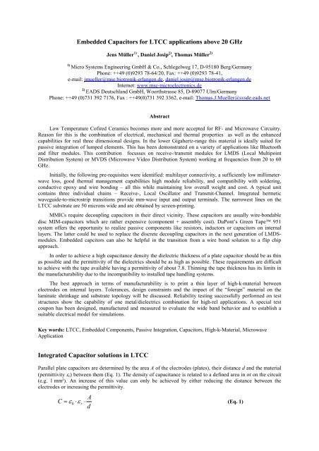
Embedded <strong>Capacitors</strong> for <strong>LTCC</strong> applications above 20 GHz<br />
Jens Müller 1) , Daniel Josip 1) , Thomas Müller 2)<br />
1) <strong>Micro</strong> <strong>Systems</strong> <strong>Engineering</strong> GmbH & Co., Schlegelweg 17, D-95180 Berg/Germany<br />
Phone: ++49 (0)9293 78-64/20, Fax: ++49 (0)9293 78-41,<br />
e-mail: jmueller@mse.biotronik-erlangen.de, daniel.josip@mse.biotronik-erlangen.de<br />
Internet: www.mse-microelectronics.de<br />
2) EADS Deutschland GmbH, Woerthstrasse 85, D-89077 Ulm/Germany<br />
Phone: ++49 (0)731 392 7176, Fax : ++49(0)731 392 3362, e-mail: Thomas.J.Mueller@sysde.eads.net<br />
Abstract<br />
Low Temperature Cofired Ceramics becomes more and more accepted for RF- and <strong>Micro</strong>wave Circuitry.<br />
Reason for this is the combination of electrical, mechanical and thermal properties as well as the enhanced<br />
capabilities for real three dimensional designs. In the lower Gigahertz-range this material is ideally suited for<br />
passive integration of lumped elements. This has been demonstrated on a variety of applications like Bluetooth<br />
and filter modules. This contribution focusses on receive-/transmit modules for LMDS (Local Multipoint<br />
Distribution System) or MVDS (<strong>Micro</strong>wave Video Distribution System) working at frequencies from 20 to 60<br />
GHz.<br />
Initially, the following pre-requisites were identified: multilayer connectivity, a sufficiently low millimeterwave<br />
loss, good thermal management capabilities high module reliability, and compatibility with soldering,<br />
conductive epoxy and wire bonding – all this while maintaining low overall weight and cost. A typical unit<br />
contains three individual chains – Receive-, Local Oscillator and Transmit-Channel. <strong>Integrated</strong> hermetic<br />
waveguide-to-microstrip transitions provide mm-wave input and output terminals. The narrowest lines on the<br />
<strong>LTCC</strong> substrate are 50 microns wide and are obtained by screen-printing.<br />
MMICs require decoupling capacitors in their direct vicinity. These capacitors are usually wire-bondable<br />
disc MIM-capacitors which are rather expensive (component + assembly cost). DuPont’s Green Tape 951<br />
system offers the opportunity to realize passive components like resistors, inductors or capacitors on internal<br />
layers. The latter could be used to replace the discrete decoupling capacitors in the next generation of LMDSmodules.<br />
Embedded capcitors can also be helpful in the transition from a wire bond solution to a flip chip<br />
approach.<br />
In order to achieve a high capacitance density the dielectric thickness of a plate capacitor should be as thin<br />
as possible and the permittivity of the dielectrics should be as high as possible. These requirements are difficult<br />
to achieve with the tape available having a permittivity of about 7.8. Thinning the tape thickness has its limits in<br />
the manufacturability due to the incompatibility to installed tape handling systems.<br />
The best approach in terms of manufacturability is to print a thin layer of high-k-material between<br />
electrodes on internal layers. Tolerances, design constraints and the impact of the “foreign” material on the<br />
laminate shrinkage and substrate topology will be discussed. Reliability testing successfully performed on test<br />
structures show the capability of one metal/dielectrics combination for high-rel applications. A special test<br />
coupon has been designed, manufactured and measured to evaluate the wide band behavior and to establish a<br />
suitable electrical model for simulations.<br />
Key words: <strong>LTCC</strong>, Embedded Components, Passive Integration, <strong>Capacitors</strong>, High-k-Material, <strong>Micro</strong>wave<br />
Application<br />
<strong>Integrated</strong> Capacitor solutions in <strong>LTCC</strong><br />
Parallel plate capacitors are determined by the area A of the electrodes (plates), their distance d and the material<br />
(permittivity r) between them (Eq. 1). The density of capacitance is related to a defined area in or on the circuit<br />
(e.g. 1 mm²). An increase of this value can only be achieved by either reducing the distance between the<br />
electrodes or increasing the permittivity.<br />
A<br />
C r<br />
d<br />
<br />
0 (Eq. 1)
In a multilayer circuit additional layers might be used to build a multilayer capacitor. However, this will mainly<br />
be a trade-off between functionality and costs.<br />
The general approaches to increase the capacitance are:<br />
a) Adding of layers (Fig. 2)<br />
b) Insertion of one layer of high-k-tape (Fig. 2a)<br />
c) Filling of holes with high-k-material (Fig. 2b)<br />
d) Locally printing high-k-paste (Fig. 2c)<br />
Type a) was not a solution due to the fixed number of layers in the application. Inserting an entire tape layer of<br />
high-k-material requires a tape which should meet the following requirements:<br />
matched shrinkage to base tape during firing<br />
tape sinters hermetically to avoid moisture penetration into the package<br />
matched TCE to base tape<br />
no material interactions with the base tape dielectrics (both ways)<br />
compatibility to conductor and via-paste systems<br />
compatibility to general tape processing methods (handling etc.)<br />
Tapes showing these properties are still under development and were not commercially available within the<br />
project time frame [1]. A solution to locally insert high-k-material has been introduced earlier [2]. This so-called<br />
tape insert array method eliminates some of the requirements mentioned above. However, the processing method<br />
is rather complex and was therefore not introduced into series production. The most promising method<br />
considered is type d) [3]. The electrodes are printed on the top of the first tape and on the rear site of the second<br />
layer. A high-k-paste is printed over the first electrode twice isolating electrode 1 from electrode 2 in the layer<br />
stack. Electrical connections to both electrodes can be realised by vias placed directly in the center of the plates<br />
or by conductor traces leaving the electrodes within the plane (Fig. 3).<br />
Fig. 1: <strong>LTCC</strong> multilayer capacitor<br />
Fig. 2: Methods to increase the density of capacitance<br />
The printing solutions addresses both variables in the capacitor design. The thickness of the dielectrics is<br />
minimised and the permittivity is increased.<br />
Fig. 3: Contact solutions for plate capacitors a) central b) peripheral
This approach requires a high-k-paste with the following features:<br />
matched shrinkage to tape during sintering<br />
pin hole free printability<br />
controlled thickness (for low capacitance variations)<br />
compatible to electrode and via materials<br />
stability to refirings<br />
Furthermore, the whole capacitor should not lead to a remarkable topology on the <strong>LTCC</strong> surface after firing.<br />
This method should therefore not be applied on tapes thinner than 130 µm or on tapes with a low<br />
compressibility. Warpage of the circuit due to a slight mismatch of the shrinkage or the TCE can be prevented by<br />
arranging the capacitors always symmetrically in the package.<br />
Printed capacitors <strong>using</strong> Green Tape 951<br />
Recently, a high-k-paste (DP5674) has been introduced for the 951 tape system. A summary of data is listed in<br />
Table 1.<br />
The capacitor is made the following way:<br />
PD bottom electrode together with the conductor lines on side 1 of layer n<br />
PD High-k-paste on side 1 of layer n<br />
PD High-k-paste on side 1 of layer n<br />
PD top electrode on side 2 of layer n+1<br />
Cofiring of all layers<br />
P = Print, D = Dry, italic printed tasks are additional steps compared to the standard processing.<br />
Compared to a postfire capacitor which requires additional firings, prints, and materials, (passiviation) the cofire<br />
solution can be obtained with a minimum effort.<br />
No. High-k- Electrode k-value tan class Density of cap. Area for<br />
Mat. material [1 MHz]<br />
pF/mm² 50pF<br />
01 5674 Ag (tbd) 60 – 80
C [pF]<br />
54<br />
52<br />
50<br />
48<br />
46<br />
44<br />
42<br />
40<br />
1 2 3<br />
Number of firings<br />
Fig. 6: Influence of the number of firings on the capacitance (min,mean,max for Ag-paste A)<br />
Paste B, a fritless Ag-paste showed less interactions with the high-k-dielectrics in general. The material<br />
combination Ag-paste B and DP 5674 lead to an overall shrinkage of 12.2%. The initial yield for fully populated<br />
substrates with 380 single capacitors in a matrix was > 98% and was stable after refirings (Fig. 7).<br />
C [pF]<br />
30<br />
29,5<br />
29<br />
28,5<br />
28<br />
27,5<br />
27<br />
26,5<br />
26<br />
C [pF] initial C [pF] Ref. 1 C [pF] Ref. 2 C [pF] Ref. 3<br />
Number of Refirings<br />
Fig. 7: Stability of capacitance vs. refirings<br />
Qualification of this system was performed on a new test structure suitable for various test conditions. Fig. 8<br />
shows the qualification test pattern. Three capacitors with different plate areas are connected in parallel<br />
(1x1mm², 2x2mm², 4x4mm²). 22 groups were placed on one coupon. The series resistors are used for limiting<br />
the maximum current in case of shorted capacitors in the biased humidity test. For pre-conditioning these<br />
substrates were refired 3 times to simulate postfire steps and went through reflow soldering and cleaning. Fig. 10<br />
shows the distribution of capacitance values for 16 test coupons. The density of capacitance was calculated to<br />
22pF/mm². Table 2 shows the qualification conditions applied and the test results. The defined target value for<br />
capacitance change was 5%. All capacitors passed this requirement.<br />
Fig. 8: Qualification test coupon
number<br />
50<br />
40<br />
30<br />
20<br />
10<br />
0<br />
145<br />
C-Testpattern cofire with 3 Refirings<br />
147<br />
149<br />
151<br />
153<br />
155<br />
157<br />
159<br />
capacitance [pF]<br />
161<br />
163<br />
165<br />
167<br />
169<br />
Fig. 9: Distribution of capacitance values<br />
Test Condition Max. Deviation from initial value Evaluation<br />
Biased humidity test 1000h 85°C/85%r.F., 10V – -0,89% Pass<br />
Temperature storage 1000h, 125°C +0,7% Pass<br />
Table 2: Qualification tests for embedded capacitors<br />
Decoupling capacitors for microwave circuits<br />
In typical microwave applications the power<br />
connections of MMICs contain decoupling<br />
capacitors. The usual value for these<br />
capacitors is 40 ... 100 pF. In order to reduce<br />
parasitic effects (wire bond inductance etc.)<br />
these capacitors are located in the direct<br />
vicinity of the IC. A standard solution with a<br />
disc capacitor is shown in Fig. 10a. Two<br />
wire bonds are necessary to connect the<br />
MMIC. A possible approach with an<br />
embedded capacitor is shown in Fig. 10b.<br />
Only one wire is necessary for the<br />
connection. Even a better solution is the<br />
combination of a buried capacitor and the<br />
use of FlipChip technology, which is<br />
considered for future applications (Fig.10c).<br />
Although the frequency requirements of<br />
these capacitors are more relaxed than in the<br />
signal path of the circuit, they should work<br />
over a wide frequency range.<br />
Fig. 10: Arrangement of decoupling<br />
capacitors in microwave applications<br />
a) traditional (chip & wire)<br />
b) embedded capacitor + chip & wire,<br />
c) embedded capacitor + FlipChip
A further test coupon was designed to evaluate the rf-behaviour. It could be demonstrated that the via connection<br />
to the upper plate has a considerable influence on the self resonant frequency. Fig. 11 shows the viaarrangements<br />
applied. Measurement results of the forward transmission parameter S21 for two 50 pF capacitors<br />
can be seen in Fig. 12. The worst behavior was obtained by the via solution from Fig. 11c (results not shown in<br />
the diagram). Capacitor 2 is connected by 2 vias in parallel, whereas capacitor 1 has only one. The increased self<br />
resonant frequency is due to the decreased parasitic inductivity (20pH vs. 45pH).<br />
Fig. 11: Via-connections to the upper capacitor plate and electrical model (lower plate is made by the<br />
ground plane)<br />
S21 [dB]<br />
0 1 2 3 4 5 6 7 8<br />
0,00<br />
-10,00<br />
-20,00<br />
-30,00<br />
-40,00<br />
-50,00<br />
-60,00<br />
-70,00<br />
Frequency [GHz]<br />
Fig. 12: Transmission behaviour of embedded capacitors with single (C1) and double (C2) via connections<br />
to the surface (shunt capacitor)<br />
Conclusions and Acknowledgements<br />
<strong>LTCC</strong> offers a suitable performance for microwave applications. Embedding of passive components will lead to<br />
a higher scale of integration and to improved electrical properties. The buried capacitors investigated in this<br />
contribution were able to demonstrate their manufacturability, reliability and rf-performance. They can be<br />
applied in future microwave products and are compatible with both the traditional chip & wire approach and<br />
FlipChip technology. The work carried out in this project is funded by the BMBF within the program<br />
“Mikrosystemtechnik 2000+” under the contract number 16SV1067/5.<br />
Literature<br />
[1] Heinz, M.R. et al.: Tape for Forming Embedded <strong>Capacitors</strong> in <strong>LTCC</strong> <strong>Systems</strong>, IMAPS International<br />
Symposium on <strong>Micro</strong>electronics, Baltimore/MD, Oct. 2001.<br />
[2] Drozdyk L.: <strong>Capacitors</strong> Buried in Green Tape, Proceedings of the International Symposium on<br />
<strong>Micro</strong>electronics, Dallas/TX, Nov. 1993.<br />
[3] Barratt, C., Ehlert, M.: Design and Manufacture of High K Printed Dielectric <strong>Capacitors</strong> for Highly<br />
<strong>Integrated</strong> RF <strong>LTCC</strong> Solutions, Proceedings of the 38th IMAPS Nordic Conference, Oslo, Sept. 2001.<br />
C1<br />
C2