View - Micro Systems Engineering
View - Micro Systems Engineering
View - Micro Systems Engineering

You also want an ePaper? Increase the reach of your titles
YUMPU automatically turns print PDFs into web optimized ePapers that Google loves.
Jens Müller, Jürgen Pohlner,<br />
Dieter Schwanke<br />
<strong>Micro</strong> <strong>Systems</strong> <strong>Engineering</strong> GmbH<br />
Schlegelweg 17<br />
D-95180 Berg/Germany<br />
Phone: +49 9293 78-0<br />
Fax: +49 9293 78 42<br />
jmueller@mse.biotronik-erlangen.de<br />
www.mse-microelectronics.de<br />
Development and Evaluation of Hermetic Ceramic<br />
<strong>Micro</strong>wave Packages for Space Applications<br />
Authors:<br />
Günter Reppe<br />
RHe <strong>Micro</strong>systems GmbH<br />
Heidestrasse 70<br />
D-01454 Radeberg/Germany<br />
Phone: +49 3528 4199-50<br />
Fax: +49 3528 4199-99<br />
guenter.reppe@rhe.de<br />
www.rhe.de<br />
Abstract<br />
Heiko Thust, Ruben Perrone<br />
Technische Universität Ilmenau<br />
<strong>Micro</strong>peripheric Group<br />
D-98684 Ilmenau/Germany<br />
Phone: +49 3677 69-2605<br />
Fax: +49 3677 69-1204<br />
Heiko.Thust@tu-ilmenau.de<br />
www.tu-ilmenau.de<br />
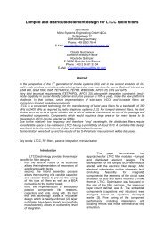
Within the KERAMIS project (funded by the German Ministry of Education and Technology) a consortium of six<br />
companies, research institutes and universities is developing ceramic based microwave packages for satellite<br />
applications. Several interface concepts like Ball Grid Array (BGA), Land Grid Array (LGA) and peripheral wire<br />
bond packages are among the candidates to realize microwave compatible connections to other modules or to the<br />
mother board. From a technology point of view the focus is put on fine line resolution and hermeticity. The latter is<br />
predominately realized by multilayer LTCC substrates sealed with metal or ceramic lids.<br />
Based on the specific function of the module, packages with and without metal heat sinks are considered. Therefore,<br />
the LTCC substrate itself needs to be hermetic. Several thermal via and transition line configurations have been<br />
investigated in the start phase of the project. Practical results will be demonstrated and design rules are derived.<br />
The test matrix contains also lead free materials for frame and heat sink soldering to be compliant with the<br />
European “Restriction of the use of Hazardous Substances” (RoHS). First results of the performance of microwave<br />
transitions up to 50 GHz will be shown.<br />
In addition to the main topic of the paper results of thin film processing for resistors will be given in the paper.<br />
Key words: LTCC, <strong>Micro</strong>wave Packages, Thermal Design, Lead Free, Thin Film, Fine Line Thick Film<br />
Introduction<br />
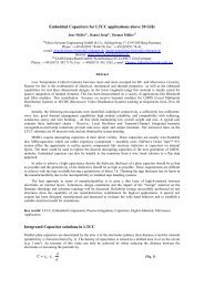
The objective of the funded program is to<br />
develop packages for space applications fulfilling the<br />
following functions and properties:<br />
Impedance matched interconnections and<br />
shielding,<br />
Embedding microwave components (divider,<br />
filters etc.),<br />
Gas-hermeticity,<br />
Interfaces to active and passive components<br />
(wire bonding, soldering, gluing),<br />
Good thermal conductivity.<br />
The package itself will be mounted on a<br />
printed circuit board with a metal core to transfer the<br />
heat from power modules assembled. Regarding the<br />
thermal management, two cases need to be<br />
considered. For low or medium power dissipation no<br />
heat sink is necessary on the package. Larger power<br />
dissipation requires an attached metal plate acting as a<br />
heat spreader and heat sink.<br />
Thermal Design Options in LTCC<br />
LTCC materials offer thermal conductivities<br />
in a range from 2 to 5 W/m*K. This seems to be high<br />
compared to organic boards which have a thermal<br />
conductivity of about 0.2 W/m*K. However, it is still<br />
not sufficient for the thermal management of a variety<br />
of applications. Typical RF-power amplifiers have a<br />
power dissipation of about 2-5 Watts. In order to<br />
prevent overheating the MMIC, the substrate<br />
underneath should provide the highest thermal<br />
conductivity possible. Additionally, the substrate<br />
thickness should be as small as possible to reduce the<br />
thermal path to the module heat sink. Thick- or thin
film alumina have a better performance regarding<br />
thermal conductivity (λ ≈ 24 W/m*K). Their weakness<br />
is, however, the hermeticity of vias through the<br />
substrate.<br />
Thermal vias in LTCC are able to improve<br />
the integral value of the thermal conductivity.<br />
Depending on the array formation (diameter of vias<br />
and pitch), values comparable to alumina or even<br />
better can be achieved [1][2].<br />
Fig. 1 shows the build-up structure of a<br />
MMIC-package mounted on a FR-4 board with<br />
thermal vias and an embedded metal core. Thermal<br />
vias in the LTCC conduct the heat to the package<br />
heatsink which act as a heat spreader. The latter is<br />
glued or soldered to the copper pad on the FR-4. It<br />
should be mentioned that the bonding methods for<br />
die, heat sink and package is important for the<br />
thermal management as well [3].<br />
Fig. 1: Build-up structure for a MMIC in a LTCC package assembled on a FR-4 board with metal core<br />
Hermeticity Test Coupon Design and Procedure<br />
Since hermeticity is a required function of<br />
the package, the thermal options need to be evaluated<br />
in more detail. The material system selected was<br />
DuPont 951AX. Due to the space application<br />
requirements, the Au conductor system was selected<br />
for the test. Vias in LTCC have a high metal content<br />
(for good conductivity) and a very low glass content<br />
as bonding agent. Therefore, bonding to the glassceramic<br />
walls is not fully achieved. Increasing the via<br />
diameter (typical for thermal vias) increases the risk<br />
for a potential leakage. For a single layer with thermal<br />
vias it is doubtful whether full hermeticity can be<br />
realized.<br />
In the study, six different design cases were<br />
considered (Fig. 2). Packages might be required with<br />
(case a and d) or without heat spreader attached. The<br />
other options are two versus four layer designs and<br />
thermal vias with or without diameter variation<br />
between layers.<br />
Fig. 2: Design options considered for the<br />
hermeticity test pattern<br />
The via diameter used are 250 µm and<br />
130 µm after firing. Furthermore, two ways of<br />
feeding signals into the package were considered.<br />
Fig. 3 shows a schematic cross section with RF<br />
feeding lines from package pads to the inner cavity.<br />
The cavity wall is used for the cover assembly which<br />
can be realized by a metal lid, kovar frame + lid,<br />
metal cover or metallized plastic cover. The reasons<br />
to investigate the two configurations were to verify<br />
the hermeticity (leakage across the line type b) as<br />
well as the electrical performance.
Fig. 3: RF-transitions into the package cavity<br />
The substrate was manufactured using<br />
standard processing conditions of LTCC. Outer layers<br />
(frame and back side) of the four layer substrate were<br />
structured by postfiring using two different solderable<br />
pastes (AuPtPd and Au-brazing). The former is<br />
intended for SnAgCu-soldering. The Au-brazing<br />
system provides optimum leaching conditions even at<br />
higher soldering temperatures as required in<br />
Au80Sn20-soldering. Fig. 4 shows the sites used for<br />
hermeticity and RF-testing on the multi-purpose<br />
substrate.<br />
Fig. 4: Hermeticity Test Coupon<br />
The die bond pad size is 3 mm by 3 mm. For<br />
future thermal assessment, dc-bias lines are routed<br />
from the outside to the inner cavity.<br />
Kovar frames with Ni/Au plating were<br />
mounted on the substrate surface in the first assembly<br />
step. For series manufacturing both the heat sink and<br />
the frame can be soldered in one step. However, for<br />
the evaluation it was necessary to check the<br />
hermeticity without the heat sink attached. Solder<br />
preforms were prepared by laser cutting. A Kester<br />
high viscosity flux for lead free soldering was used to<br />
activate the joints and to keep the frames in place. For<br />
SnAgCu soldering a standard reflow oven (BTU<br />
Pyramax) was used as an alternative to vacuum<br />
soldering. After frame soldering the flux residues<br />
were cleaned in an IPA-based solution with ultrasonic<br />
support. Helium fine leak testing was performed<br />
upside-down (Kovar frame on a rubber seal)<br />
according to MIL-Std. 883F, Method 1014.11, test<br />
condition A4 (leak rate < 10 -8 atm cc/s).<br />
Heat sinks made of Molybdenum were<br />
soldered during the second phase of assembly in a<br />
vacuum process (gas phase activation). Fine leak<br />
testing was done again to monitor any hermeticity<br />
changes. Fig. 5 shows an example of a test package<br />
after heat sink soldering.<br />
Fig. 5: Test package with Kovar frame and Mo<br />
heat sink<br />
Finally, several parts were X-rayed for solder<br />
joint evaluation.<br />
Hermeticity Test Results<br />
No He-leak problems could be assigned to<br />
the solder joints after optimizing the soldering<br />
parameters. Both SnAgCu and AuSn solder behaved<br />
similar. Major problems were related to the stack of<br />
vias with large diameter. Table 1 contains the results<br />
of all test groups. On the 2-layer design, 80% of the<br />
stacked via packages (250 µm) were not hermetic.<br />
Even with two more layers, still 60% showed failures.<br />
The concept of alternating the via diameter yielded<br />
better results. The failure rate could be reduced to<br />
20% on the 2-layer design and down to zero for four<br />
layers. The position of the feeding lines had no<br />
impact on hermeticity. After heat sink soldering, all<br />
previously defective modules passed the He fine leak<br />
test.
Heatsink Via stack Type Failure [%]<br />
w/o<br />
w/o<br />
2 layer<br />
4 layer<br />
Stripline (Fig. 3a) 0<br />
Coplanar line (Fig. 3b) 0<br />
Constant via diameter: 250 µm (Fig. 2b) 80<br />
Altern. via diameter: 250/130µm (Fig. 2c) 20<br />
Constant via diameter: 250 µm (Fig. 2e) 60<br />
Altern. via diameter: 250/130µm (Fig. 2f) 0<br />
with all types all types (Fig. 2a/d) 0<br />
X-ray analysis revealed no major problems<br />
with heat sink soldering. Heat sinks soldered with<br />
AuSn had small voids (less than 10%) whereas the<br />
SnAgCu solder was almost void free (Fig. 6 and 7).<br />
Fig. 6: X-ray picture of a heat sink soldered with<br />
AuSn (small voids visible)<br />
Fig. 7: X-ray picture of a heat sink soldered with<br />
SnAgCu<br />
Table 1: He fine leak test results<br />
Package RF Performance<br />
The two line configurations (Fig. 3) needed<br />
to be optimized for best wave impedance control [4].<br />
Critical areas are the transitions underneath the wall<br />
to enter the inner cavity. The dielectric cover causes<br />
an impedance step towards lower values. Therefore, a<br />
line width reduction is mandatory for compensation.<br />
Vias, surrounding the lines for shielding purposes and<br />
ground connection, play an important role for the<br />
wide band behaviour of the transition. Their location,<br />
size and pitch determine the maximum possible<br />
frequency with low return loss. Fig. 8 and 9 depict the<br />
structure of the transition for both line types.<br />
CST <strong>Micro</strong>wave Studio was used to simulate<br />
and optimize the transitions.<br />
Fig. 8: Structural model of the stripline<br />
configuration<br />
The outer connection was designed as a<br />
grounded coplanar line allowing direct contacting<br />
with microwave probes (250 µm pitch). The test<br />
packages were measured with a network analyser and<br />
Z-Probes from SÜSS <strong>Micro</strong>Tech up to 50 GHz<br />
between the two outer connections (4 line transitions).<br />
Measurement results are shown in Fig. 10.
S11 [dB]<br />
Fig. 9: Structural model of the coplanar line<br />
configuration<br />
0<br />
-10<br />
-20<br />
-30<br />
-40<br />
-50<br />
-60<br />
Frequency [Hz] [GHz]<br />
0 10 20 30 40 50<br />
Line transition type a. Line transition type b.<br />
Fig. 10: Return loss measurement (S11)<br />
for the both packages<br />
The packages with CPWG-stripline-CPWG<br />
line transitions (type a) show a good impedance<br />
match up to 18 GHz. At frequencies above this value<br />
the reflection coefficient (S11) increases very fast.<br />
The packages with the line transitions type b<br />
show excellent impedance matching up to 50 GHz.<br />
Thin film on LTCC<br />
Thin film structuring on LTCC is a part of<br />
the research program conducted by RHe<br />
<strong>Micro</strong>systems. Line widths and spaces down to<br />
10 µm have been realized on DP 951 [5]. Since<br />
resistors with small dimensions and high precision are<br />
required for several microwave structures (e.g.<br />
terminations, dividers etc.) thin film resistor materials<br />
on LTCC were examined in detail.<br />
The following two different layer systems<br />
were deposited on LTCC:<br />
1. CrNi / Cu (sputtered) - CuNiAu (electroplated)<br />
for CrNi-resistors<br />
2. TaN / TiW / Au (sputtered) - Au (electroplated)<br />
for Tantalnitride-resistors<br />
CrNi can be used in the first mentioned layer<br />
system both as adhesion layer and as resistance layer.<br />
TaN is not suitable as an adhesion layer and is used as<br />
resistance layer only. Al2O3 substrates were added to<br />
the test matrix as controls.<br />
Sputter conditions were chosen for these<br />
resistance materials according to known Al2O3<br />
parameters to obtain square resistances (Rsq) of 20, 50<br />
and 100 Ω respectively. Different resistor geometries<br />
with length/width-ratios between 1:5 and 500:1 were<br />
produced and examined. The minimum resistor width<br />
was 50 µm.<br />
Fig. 11 shows the relative resistance values<br />
for both CrNi- and TaN-resistors and several Rsq in<br />
comparison to Al2O3-ceramics. A possible<br />
explanation for the lower resistance is the smaller<br />
„micro roughness” of LTCC compared to alumina<br />
[5].<br />
dR/R Al2O3 [%]<br />
0<br />
-5<br />
-10<br />
-15<br />
-20<br />
-25<br />
-30<br />
-35<br />
-40<br />
-45<br />
-50<br />
Resistance related to Al2O3<br />
20 Ohm/sq 50 Ohm/sq 100 Ohm/sq<br />
Fig. 11: Resistance values of CrNi and TaN thin<br />
film resistors on LTCC normalized to Al2O3 for<br />
the length to width ratio of 107:1<br />
No differences were observed between the<br />
different Rsq for TaN-resistors whereas CrNi resistors<br />
with a Rsq of 20 Ω tend to be lower than expected.<br />
The determined hot thermal coefficients of resistance<br />
(HTCR) between + 25°C and + 125°C are even more<br />
interesting. (Fig. 12/13).<br />
It is obvious that CrNi-resistors with Rsq =<br />
20 Ω are not suitable for the use on LTCC. The<br />
negative tempering shift after 6 hours at 250 °C is<br />
another indicator (typical shift is between +5 and<br />
+15%). For 50 Ω/sq and higher values the HTCR is<br />
only 5 ppm/K lower than on Al2O3, and is therefore<br />
acceptable.<br />
CrNi<br />
TaN
HTCR [ppm/K]<br />
70<br />
60<br />
50<br />
40<br />
30<br />
20<br />
10<br />
0<br />
-10<br />
-20<br />
-30<br />
CrNi<br />
20 Ohm/sq 50 Ohm/sq 100 Ohm/sq<br />
Al2O3<br />
LTCC<br />
Fig. 12: HTCR of CrNi on LTCC and alumina for<br />
various resistances (l/b=107:1)<br />
HTCR [ppm/K]<br />
0<br />
-20<br />
-40<br />
-60<br />
-80<br />
-100<br />
-120<br />
TaN<br />
20 Ohm/sq 50 Ohm/sq 100 Ohm/sq<br />
Al2O3<br />
LTCC<br />
Fig. 13: HTCR of TaN on LTCC and alumina for<br />
various resistances (l/b=107:1)<br />
The principally higher thickness of Tantal<br />
Nitride compared with CrNi lead to more stable<br />
conditions. The measured HTCR-values of TaN on<br />
LTCC do not differ from those on Al2O3, (usually<br />
from -90 to -110 ppm /K).<br />
Laser trimming of thin film resistors could<br />
be carried out without any difficulties. Fig. 14 shows<br />
a resistor with the geometry of l = 10,7 mm and b =<br />
100 µm after trimming. Tolerances in the range of<br />
± 1% can be achieved. First stability tests (1000 h @<br />
150 °C) have already indicated positive results.<br />
Fig. 14: Laser trimmed thin film CrNi resistor<br />
Summary and Outlook<br />
Design constraints for hermetic packages<br />
were determined. It has been shown that thermal via<br />
designs have an impact on module hermeticity. Cost<br />
effective lead free solder was successfully used for<br />
sealing LTCC packages. The package designs allow<br />
RF transitions which are capable up to frequencies<br />
over 40 GHz.<br />
Regarding thin film resistors on LTCC it can<br />
be concluded that TaN-resistors are very suited<br />
because of the quite comparable behaviour to<br />
alumina. In general, also CrNi resistors can be applied<br />
on LTCC 951 with the exception of the low resistance<br />
value.<br />
Future work within the project will focus on<br />
the thermal assessment of hermetic packages and the<br />
evaluation of different packaging concepts in terms of<br />
RF and thermal management.<br />
Acknowledgements<br />
The authors would like to thank the German<br />
Government for the financial support. The work<br />
carried out in the project Keramis is funded by the<br />
BMBF under the project number 50 YB 0316.<br />
References<br />
[1] M. Ray Fairchild et al.: LTCC Technologies for Harshenvironment<br />
Automotive Applications Utilizing Soldered<br />
Interconnections, Proceedings of the 37 th International<br />
Symposium on <strong>Micro</strong>electronics, Nov. 14-18, 2004, Long<br />
Beach, CA.<br />
[2] Dan Amey, Mimi Keating: Thermal Performance of 943<br />
Low Loss Green Tape LTCC with Thermal Via and Internal<br />
Metallization Enhancements, Proceedings of the 2004<br />
Ceramic Interconnect Technology Conference, April 26-28,<br />
2004, Denver/CO, USA.<br />
[3] Yasunari Ukita et al.: Lead free die mount adhesive<br />
using silver nanoparticles applied to power discrete<br />
package, Proceedings of the 37 th International Symposium<br />
on <strong>Micro</strong>electronics, Nov. 14-18, 2004, Long Beach, CA.<br />
[4] Ruben Perrone et al.: Development and Evaluation of<br />
Photodefined Elements for <strong>Micro</strong>wave Modules in LTCC<br />
for Space Applications, 14 th European <strong>Micro</strong>electronics and<br />
Packaging Conference, June 12-15, 2005, Brugge/Belgium.<br />
[5] Günter Reppe et al.: Development and Evaluation of<br />
Fine Line Structuring Methods for <strong>Micro</strong>wave Packages in<br />
Satellite Applications, 14 th European <strong>Micro</strong>electronics and<br />
Packaging Conference, June 12-15, 2005, Brugge/Belgium.