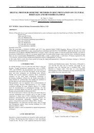
saving voskopoja, complete photogrammetric coverage of ... - CIPA
saving voskopoja, complete photogrammetric coverage of ... - CIPA
saving voskopoja, complete photogrammetric coverage of ... - CIPA

Create successful ePaper yourself
Turn your PDF publications into a flip-book with our unique Google optimized e-Paper software.
________<strong>CIPA</strong> 2005 XX International Symposium, 26 September – 01 October, 2005, Torino, Italy________<br />
SAVING VOSKOPOJA, COMPLETE PHOTOGRAMMETRIC COVERAGE<br />
OF THREE ALBANIAN PAINTED CHURCHES<br />
T. Leroy<br />
Art Graphique et Patrimoine, 15 avenue J. Jaurès, F-94340 Joinville le Pont, France<br />
Email: t.leroy@artgp.fr<br />
KEY WORDS: Church, Digital Photogrammetry, Image Unwrapping, Preservation, Rectification<br />
ABSTRACT<br />
This paper gives an overview <strong>of</strong> the way to produce exhaustive multi-user documentation <strong>of</strong> an endangered site in Albania through<br />
<strong>photogrammetric</strong> applications. The complexity <strong>of</strong> the structures to be documented has led us to use a large range <strong>of</strong> available<br />
<strong>photogrammetric</strong> and survey techniques. The development <strong>of</strong> low-cost <strong>photogrammetric</strong> material: s<strong>of</strong>tware, cameras, personal<br />
computers, <strong>of</strong>fers the possibility to achieve quickly the survey and restitution <strong>of</strong> complex architectures and frescoes. Though methods<br />
to document frescoes are already well described in the literature, we have to spread their use by convincing the users <strong>of</strong> their utility,<br />
and to find ways to produce unwrapped documents even more quickly and accurately as the classical <strong>photogrammetric</strong><br />
documentation.<br />
1. INTRODUCTION<br />
Voskopoja (south Albania), located 35 km from the Greek<br />
border, was a renowned orthodox pilgrimage centre in the<br />
XVIIIth century. All that remains <strong>of</strong> this prestigious past are six<br />
churches and a monastery. Well preserved externally, the<br />
interiors are <strong>complete</strong>ly covered with frescoes. Unfortunately,<br />
the frescoes have been badly damaged by water infiltration and<br />
continue to deteriorate.<br />
The French non-government association Patrimoine sans<br />
Frontières (or “PSF”) discovered the slow deterioration <strong>of</strong> the<br />
treasures <strong>of</strong> Voskopoja around 2002. Following the creation <strong>of</strong> a<br />
scientific committee, comprising members <strong>of</strong> PSF, the ENP<br />
(Ecole Nationale du Patrimoine, Paris), architects, and the IMK<br />
(Albanian Culture Ministry), the initial step was to<br />
comprehensively and precisely document the interiors and<br />
exteriors <strong>of</strong> the three most endangered churches, which would<br />
underlie all future works and restorations.<br />
In Voskopoja, only scarce paper documentation existed.<br />
Architects, restorators, art historian were in need <strong>of</strong> documents<br />
to report their analysis, plan their future works (scaffolding<br />
implantation, frescoes restoration...), and compare the churches<br />
with others in Albania, Greece and Macedonia.<br />
Architects needed 2D CAD drawings showing the main<br />
volumes, indeed as the churches are quite internally <strong>complete</strong>ly<br />
covered with frescoes (90%), it is very difficult to estimate and<br />
understand the spatial internal organisation.<br />
Restorators needed a <strong>complete</strong> documentation <strong>of</strong> frescoes only<br />
in an easily understandable way. The external aspect <strong>of</strong> the<br />
churches is simple but, in the inside, the game <strong>of</strong> arches, and<br />
domes makes the comprehension impossible without<br />
enlightening documents such as rectified and unwrapped<br />
images.<br />
It has been decided to produce a documentation that could<br />
satisfy all the users and constitute an exhaustive geometric<br />
database to conduct works. This <strong>complete</strong> record is a geometric<br />
and radiometric memory that virtually stops the damages’<br />
extent.<br />
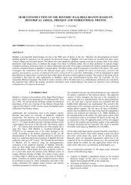
For each church the following documents had so to be drew:<br />
1. CAD drawings at scale 1/50: inside/outside horizontal<br />
section, multiple longitudinal and transversal sections in a<br />
manner to see each wall, exterior elevations.<br />
2. Rectified images at scale 1/20: any surface had to be<br />
documented as an unwrapped image or an orthophoto. This<br />
includes walls, ground, arches and domes.<br />
Figure 1. Saint Athanase, sections and elevations situation.<br />
The survey and evaluation mission took place during the<br />
summer <strong>of</strong> 2003, with members <strong>of</strong> the scientific committee and<br />
Art Graphique.<br />
2. DATA ACQUISITION<br />
As the list and type <strong>of</strong> documents to establish was set, it became<br />
thus possible to define the way to do it properly in time. Other<br />
facts came moreover into account: the way from France to<br />
Albania and Voskopoja is not an easy one especially for<br />
sensitive material. Once at the airport in Tirana, 6 hours <strong>of</strong> car<br />
are requested to join the spot.<br />
A rugged, well known and robust material has been chosen to<br />
avoid any breakdown: a reflectorless tacheometer, a reflex<br />
camera Fuji S2 Pro (2014*3010 CCD sensor) with precalibrated<br />
short focals (15mm, 24mm, 30 mm) and a set <strong>of</strong><br />
powerful flash lamps.<br />
A power generator was bought in Korce to ensure local<br />
lightning and alimentation <strong>of</strong> portable computers. Three or four<br />
days were allowed for each church because a strict survey<br />
planning had been scheduled in France.<br />
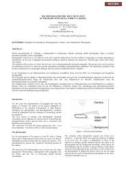
2.1 Photographs<br />
For the photographs, some tables (see below) helped to evaluate<br />
the maximum distances to the object according to the focal<br />
length, to guaranty an optimal radiometric record.
________<strong>CIPA</strong> 2005 XX International Symposium, 26 September – 01 October, 2005, Torino, Italy________<br />
Focal length<br />
Maximum distance to<br />
the object<br />
Terrain maximum<br />
image size<br />
15 mm 3.3 m<br />
24 mm 5.3 m<br />
5.1 m * 3.4 m<br />
30 mm 6.6 m<br />
Table 1. Shot parameters according to the focal length,<br />
calculated at scale 1/20 for a 300 dpi plot (physical optimal<br />
pixel size: 1.7 mm).<br />
The goal was to avoid thinking too much during the acquisition;<br />
this phase had to be quite mechanical. Each part <strong>of</strong> the church<br />
was photographed from three points <strong>of</strong> view. The camera was<br />
connected to a portable computer and every shot quality was<br />
checked before to be recorded. Furthermore, precise zoning<br />
helped to classify the data for future uses (one cell is referred to<br />
by its situation on transversal and longitudinal section i.e.: T6L1<br />
refers to the SW corner cell).<br />
2.2 Survey<br />
For the survey, a list <strong>of</strong> details to measure was available in order<br />
not to forget anything for each tacheometer station: natural<br />
control points for ground and walls, sections, plan etc.<br />
Polygonal measurement and survey were conducted at the same<br />
time to go faster. Round-trip distances and level differences<br />
were checked each evening and the polygonal least-square<br />
adjustment was performed on the last day as a final check to<br />
conclude a church survey.<br />
Figure 2. Raw data directly extracted from the coded survey<br />
system.<br />
The horizontal and vertical sections were measured through a<br />
coded survey system connected to the tacheometer that helped<br />
doing quickly a more reliable work. It permits to avoid sketches<br />
and to directly do the interpretation while surveying, decreasing<br />
thus the <strong>of</strong>fice work (Figure 2). As we said upper, painted<br />
surfaces make the estimation <strong>of</strong> volume details very difficult on<br />
photographs. Measuring directly the sections with a reflectorless<br />
tacheometer permitted to skip a difficult and time consuming<br />
step in convergent photogrammetry.<br />
By calculating the polygonal line on site at the end <strong>of</strong> the<br />
survey, we could check the survey completion and then<br />
manually measure the lacks.<br />
This procedure, easy to implement, sure and quick, saves 80%<br />
time at the <strong>of</strong>fice.<br />
3. PHOTOGRAMMETRIC WORKS<br />
3.1 Photogrammetric adjustment<br />
In view <strong>of</strong> the diversity <strong>of</strong> the final documents, the processing<br />
step was carefully scheduled not to lose time uselessly.<br />
However, fortunately not all the photographs needed to be<br />
adjusted. Actually camera positions were calculated only to<br />
determine some details (capitals, columns...) by convergent<br />
photogrammetry or to deal with the photographic representation<br />
<strong>of</strong> the ceilings.<br />
As the number and reliability <strong>of</strong> the control points were high, no<br />
global adjustment was necessary. At least five control points<br />
were visible on each block so a locally adjusted image inserts<br />
itself perfectly in the object space.<br />
Figure 3. Inside and outside 3D control points.<br />
The different focal lengths were calibrated in France but a<br />
control was conducted in Albania to check the camera stability<br />
in case <strong>of</strong> a shock during the transport; it revealed no<br />
significative change.<br />
3.2 Flat surfaces<br />
Flat surfaces or supposed so (i.e. walls and ground) were<br />
processed using projective rectification which parameters are<br />
set from the multiple control points. For this purpose the camera<br />
distortions, important with short focals are taken into account.<br />
However, we rapidly noticed that the frescoes’ structure would<br />
be a serious problem. Indeed the frescoes are painted on a fresh<br />
plaster layer roughly spread on the masonry. It induces that not<br />
any surfaces is really flat. To minimize this volume effect that<br />
creates inaccuracies in the rectified images, photographs were<br />
taken the most orthogonally to the surface and with the longest<br />
focal possible.<br />
The rectified images are directly connected to the average plane<br />
defined by the control points and can be then automatically<br />
mosaïcked via this link to the object space. The final touch up is<br />
performed under the Gimp s<strong>of</strong>tware; it consists in adjusting the<br />
corresponding radiometries and the little geometric<br />
discontinuities mainly due to the imperfect flatness <strong>of</strong> the<br />
surfaces. A layer containing the control points helps to check<br />
the final accuracy evaluated to 2 cm.
________<strong>CIPA</strong> 2005 XX International Symposium, 26 September – 01 October, 2005, Torino, Italy________<br />
3.3 Curved analytical surfaces<br />
3.3.1 Transverse arches and barrel arches<br />
Cylindrical arches had to be unwrapped to be presented as flat<br />
images. Special procedure developed for castle towers and<br />
curved elevations, previously programmed, were used.<br />
To produce an unwrapped image, some important parameters<br />
have to be set (Figure 4):<br />
1. Cylinder parameters: a full 3D approach is used to spatially<br />
determine a cylinder; a fixed point P0 (X 0, Y 0, Z 0), three<br />
rotations using a topographical system (α, ν, κ) to orient<br />
the y axis cylinder system (Kraus, 1996, p.16) and the<br />
radius. Some <strong>of</strong> these parameters have no influence (one <strong>of</strong><br />
X0, Y 0 or Z 0 can always be set to zero and κ is always set<br />
to zero) reducing them to five. These parameters are<br />
evaluated through a set <strong>of</strong> control points by an iterative<br />
surface fitting process using approached values.<br />
2. Camera position: the camera position is essential, as<br />
multiple points <strong>of</strong> views were needed because <strong>of</strong> the<br />
beams, we chose a bundle block adjustment instead <strong>of</strong> a<br />
DLT.<br />
3. Spatial interest zone to unwrap: four parameters (two<br />
angles: αd and αf, two distances to P 0: yd and yf) define<br />
this area on the cylinder.<br />
4. Final pixel size for the resampling (1.7 mm and bilinear<br />
interpolation).<br />
Figure 4. Cylinder unwrapping parameters (α=-97gr, ν=4gr)<br />
For each pixel <strong>of</strong> the unwrapped image, the corresponding XYZ<br />
position is found, and then by ray-tracing the 3D point into the<br />
original image, the ij position gives the RGB value (Karras,<br />
1997).<br />
Typically, several images are necessary to record the whole<br />
arch, the unwrapped images are mosaïcked then geometrically<br />
and radiometrically adapted. Of course, by using an analytical<br />
surface, this technique is dependant to the real shape <strong>of</strong> the<br />
cylinder. As we said upper, the frescoes’ support is roughly flat<br />
and the damaged areas vary from the ideal shape. These areas,<br />
visible from different points <strong>of</strong> view create inaccuracies that are<br />
corrected in the mosaïcking step.<br />
This procedure was applied successfully to the barrel arches.<br />
However, by studying the surface fitting results and the<br />
unwrapped images <strong>of</strong> the arches, we noticed that the results<br />
could be a lot better. Due to their deformations, the arches’<br />
section is not a circle but looks like a basket handle composed<br />
<strong>of</strong> several circles. We have changed the approach for the arches<br />
by working the CAD drawings where the exact arches’ pr<strong>of</strong>ile<br />
was visible (Figure 5).<br />
Figure 5. The transversal section T4 (view to the east) and the<br />
main transverse arch composed <strong>of</strong> four cylinders implemented<br />
as an extruded surface (result in Fig. 11).<br />
An arch was considered as an extruded surface which pr<strong>of</strong>ile<br />
was defined in the CAD drawings. Due to their small width (no<br />
more than 60cm) the direction <strong>of</strong> extrusion didn’t need high<br />
accuracy and was set perpendicular to the section plan.<br />
We thus developed a multi-cylinder unwrapping procedure; the<br />
user had just to select the pr<strong>of</strong>ile and direction <strong>of</strong> extrusion<br />
(composed <strong>of</strong> polylines) in Autocad. A lisp macro automatically<br />
wrote a text file containing the cylinders’ parameters. The<br />
program successively unwrapped the different parts <strong>of</strong> the<br />
original image and sticked them together.<br />
The different ‘multi-unwrapped’ images are mosaïcked as<br />
precedently.<br />
This way <strong>of</strong> unwrapping arches permits to eliminate a great part<br />
<strong>of</strong> the geometric discrepancies in the final images. It also<br />
permits to unwrap in one step more complex shapes composed<br />
<strong>of</strong> plans and several cylinders (plans are then considered as<br />
cylinder with quite infinite radius).<br />
However this solution has to be handled with care when dealing<br />
with long extrusion distances.<br />
Figure 6. A clover-unwrapping <strong>of</strong> a groined arch in the cell<br />
T5L3.<br />
The unwrapped arches had also to be represented as orthophotos<br />
in the sections. A special program was created therefore to<br />
reduce the unwrapped images to orthophotos according to their<br />
average radiuses (Figure 10).<br />
Eighteen transversal arches, six barrel arches and four cloverunwrapping<br />
(Figure 6) have been achieved in the Saint<br />
Athanase church.
________<strong>CIPA</strong> 2005 XX International Symposium, 26 September – 01 October, 2005, Torino, Italy________<br />
3.3.2 Circular domes<br />
The domes had also to be documented as raster projection. Due<br />
to their spherical shape, a different approach is necessary.<br />
Indeed the double curved surfaces are not developable without<br />
any compromise i.e. it is compulsory to chose a flat<br />
representation system <strong>of</strong> the sphere (or projection). The choice<br />
<strong>of</strong> this projection is crucial because some properties (angles,<br />
surfaces, distances) can be retained but not together. Angles are<br />
retained in conformal projections, surfaces in area equivalent<br />
projections and other projections can retain distances (only for<br />
particular lines).<br />
Area-equivalent projections are <strong>of</strong>ten interesting for restoration<br />
purposes because the amount <strong>of</strong> work and material needed is<br />
then easier to evaluate but they conduct to heavy distortions too<br />
difficult to manage to have a faithful view <strong>of</strong> reality.<br />
The orthographic projection has been chosen because it<br />
facilitated the insertion <strong>of</strong> the raster projections in the final<br />
documents: sections and plan <strong>of</strong> the ceiling (Figure 9). Actually<br />
it consists in orthophotos <strong>of</strong> the circular domes.<br />
The treatment is rather similar to the one applied to the<br />
cylinders, a previously used program performed the projection<br />
and, fortunately, the surface fitting algorithm did not reveal any<br />
important deformation.<br />
A dome is projected on five directions, four lateral orthogonal<br />
projections and a ground projection. To simplify the process, a<br />
transfer raster image whose coordinates (i,j) are the spherical<br />
coordinates (φ,λ) is created. It consists in the simplest existing<br />
projection and is known as a flat square representation. It acts as<br />
a data source for all type <strong>of</strong> projections (Guerra, 2000).<br />
3.4. Other domes<br />
For the documentation <strong>of</strong> the remaining domes we decided to<br />
present them in the same way that the cupolas with a five<br />
directions projection.<br />
Figure 7. The dome in the cell T4L2. Left the mesh describing<br />
the surface, right the textured photo-model. Below, the<br />
orthophoto.<br />
Nevertheless, it is difficult to adapt representation systems to<br />
non-analytical surfaces. The simplest way to perform this<br />
documentation was to create a 3D model <strong>of</strong> the dome by<br />
convergent photogrammetry and to texture it. This task was<br />
perfectly performed in Photomodeler. The exported photomodel<br />
was rendered in the five interest directions and the raster<br />
projection was then inserted in the sections besides the other<br />
domes.<br />
Though simple, this way to proceed is much longer than the<br />
treatment <strong>of</strong> analytical surfaces because <strong>of</strong> the definition <strong>of</strong> the<br />
real shape <strong>of</strong> the domes that demands many points to obtain an<br />
accurate mesh (Figure 7).<br />
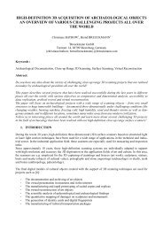
4. CONCLUSION<br />
As a result, the diversity and complementarity <strong>of</strong> the techniques<br />
employed has permitted to achieve this challenging survey. The<br />
restoration works began during summer 2004 and continue in<br />
2005 with French, Greek and German restorators. The ro<strong>of</strong> <strong>of</strong><br />
the Saint-Athanase church has been changed in early 2004<br />
contributing to preserve the inside.<br />
The other two surveyed churches are not yet processed.<br />
REFERENCES<br />
Guerra, F., Miniutti, D.: The cartographic projections for the<br />
representation <strong>of</strong> double curved surfaces. International Archives<br />
<strong>of</strong> Photogrammetry and Remote Sensing, Vol. XXXIII, Part B5,<br />
Amsterdam, 2000, pp. 533-538.<br />
Karras, G. E., Patias, P., Petsa, E., Ketipis, K.: Raster projection<br />
and development <strong>of</strong> curved surfaces. International Archives <strong>of</strong><br />
Photogrammetry and Remote Sensing, Vol. XXXII, Part 5C1B,<br />
Göteborg, 1997, pp. 179-185.<br />
Kraus, K., Photogrammetrie, Band 2 Verfeinerte Methoden und<br />
Anwendungen, 1996, Dümmler Verlag, Bonn.
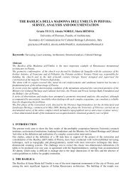
________<strong>CIPA</strong> 2005 XX International Symposium, 26 September – 01 October, 2005, Torino, Italy________<br />
A. Original images<br />
B. The final mosaïcked document.<br />
C. Details at scale 1/20 and 1/10<br />
Figure 8. Digital unwrapping <strong>of</strong> the partially cylindrical apse. (R=1.83m, σ R=1.1cm)
________<strong>CIPA</strong> 2005 XX International Symposium, 26 September – 01 October, 2005, Torino, Italy________<br />
Figure 9. Orthophotos <strong>of</strong> the circular dome T5L2, left the lateral projections and right the ground projection. (R= 1.94m, , σ R=2.3cm)<br />
Figure 10. Longitudinal section L2 (view to the north) through the apse and orthophoto.<br />
Figure 11. A multi-cylinder unwrapped image (four cylinders and two plans are composing the extruded pr<strong>of</strong>ile).