3D Reconstruction of the Historic Baalbek/Lebanon Based on ... - CIPA
3D Reconstruction of the Historic Baalbek/Lebanon Based on ... - CIPA
3D Reconstruction of the Historic Baalbek/Lebanon Based on ... - CIPA

Create successful ePaper yourself
Turn your PDF publications into a flip-book with our unique Google optimized e-Paper software.
<str<strong>on</strong>g>3D</str<strong>on</strong>g> RECONSTRUCTION OF THE HISTORIC BAALBEK/LIBANON BASED ON<br />
HISTORICAL AERIAL, OBLIQUE AND TERRESTERIAL PHOTOS<br />
A. Alamouri a , L. Gruendig b<br />
Institute for Geodesy and Geoinformati<strong>on</strong>, Technical University <str<strong>on</strong>g>of</str<strong>on</strong>g> Berlin, Straße des 17. Juni, 10623 Berlin, Germany<br />
alamouri@mailbox.tu-berlin.de, gruendig@inge3.bv.tu-berlin.de<br />
Commissi<strong>on</strong> V, WG V/2<br />
KEY WORDS: Orientati<strong>on</strong>, Orthophoto, Mosaic, Geometry, Distorti<strong>on</strong>, <str<strong>on</strong>g>Rec<strong>on</strong>structi<strong>on</strong></str<strong>on</strong>g><br />
ABSTRACT:<br />
<str<strong>on</strong>g>Baalbek</str<strong>on</strong>g> is an important urban heritage site due to <str<strong>on</strong>g>the</str<strong>on</strong>g> 5000 years <str<strong>on</strong>g>of</str<strong>on</strong>g> history in <str<strong>on</strong>g>the</str<strong>on</strong>g> city. Therefore, <str<strong>on</strong>g>the</str<strong>on</strong>g> documentati<strong>on</strong> <str<strong>on</strong>g>of</str<strong>on</strong>g> historic<br />
<str<strong>on</strong>g>Baalbek</str<strong>on</strong>g> should be respected. For this purpose <str<strong>on</strong>g>the</str<strong>on</strong>g> historical images <str<strong>on</strong>g>of</str<strong>on</strong>g> <str<strong>on</strong>g>Baalbek</str<strong>on</strong>g> were used which are classified into three types:<br />
vertical, oblique and terrestrial photos. The photos have poor properties (different cameras used and no primary data <str<strong>on</strong>g>of</str<strong>on</strong>g> <str<strong>on</strong>g>the</str<strong>on</strong>g> camera<br />
parameters, high image noise, in additi<strong>on</strong> <str<strong>on</strong>g>the</str<strong>on</strong>g> images were taken in different dates). Due to <str<strong>on</strong>g>the</str<strong>on</strong>g>se properties an optimal images<br />
orientati<strong>on</strong> should be enforced to know by which combinati<strong>on</strong> and order <str<strong>on</strong>g>of</str<strong>on</strong>g> <str<strong>on</strong>g>the</str<strong>on</strong>g> images orientati<strong>on</strong> <str<strong>on</strong>g>the</str<strong>on</strong>g> optimal orientati<strong>on</strong> parameters<br />
could be estimated. <str<strong>on</strong>g>Based</str<strong>on</strong>g> <strong>on</strong> <str<strong>on</strong>g>Baalbek</str<strong>on</strong>g>’s oriented photos <str<strong>on</strong>g>3D</str<strong>on</strong>g> object points could be measured to rec<strong>on</strong>struct <str<strong>on</strong>g>3D</str<strong>on</strong>g> objects. This paper<br />
investigates <str<strong>on</strong>g>the</str<strong>on</strong>g> combinati<strong>on</strong> between <str<strong>on</strong>g>the</str<strong>on</strong>g> different image types to achieve an optimal <str<strong>on</strong>g>3D</str<strong>on</strong>g> object rec<strong>on</strong>structi<strong>on</strong>; moreover, <str<strong>on</strong>g>the</str<strong>on</strong>g><br />
geodetic and geometric accuracy <str<strong>on</strong>g>of</str<strong>on</strong>g> additi<strong>on</strong>al <str<strong>on</strong>g>3D</str<strong>on</strong>g> points extracted will be c<strong>on</strong>trolled. Additi<strong>on</strong>ally, it will be determined in which<br />
photo/photos an object point is existed and from which photo this point could be optimal recorded. The results <str<strong>on</strong>g>of</str<strong>on</strong>g> this study will be<br />
c<strong>on</strong>sidered a data base for o<str<strong>on</strong>g>the</str<strong>on</strong>g>r applicati<strong>on</strong>s in <str<strong>on</strong>g>Baalbek</str<strong>on</strong>g>’s space (e.g. Geoinformati<strong>on</strong> System GIS, <str<strong>on</strong>g>3D</str<strong>on</strong>g> CityGML: <str<strong>on</strong>g>3D</str<strong>on</strong>g> City<br />
Geography Markup Language). This leads to create a c<strong>on</strong>cept, with it, <str<strong>on</strong>g>the</str<strong>on</strong>g> o<str<strong>on</strong>g>the</str<strong>on</strong>g>r users (e.g. archaeologists, architects, etc.) can derive<br />
<str<strong>on</strong>g>the</str<strong>on</strong>g> requested data without <str<strong>on</strong>g>the</str<strong>on</strong>g> primary geometric informati<strong>on</strong> from oriented photos; that means an interactive and web-based<br />
evaluati<strong>on</strong> has to be taken in <str<strong>on</strong>g>the</str<strong>on</strong>g> account.<br />
1. INTRODUCTION<br />
<str<strong>on</strong>g>Baalbek</str<strong>on</strong>g> is situated <strong>on</strong> <str<strong>on</strong>g>the</str<strong>on</strong>g> nor<str<strong>on</strong>g>the</str<strong>on</strong>g>rn <str<strong>on</strong>g>of</str<strong>on</strong>g> <str<strong>on</strong>g>the</str<strong>on</strong>g> Beqaa-Plain/Liban<strong>on</strong><br />
which was settled in <str<strong>on</strong>g>the</str<strong>on</strong>g> beginning <str<strong>on</strong>g>of</str<strong>on</strong>g> 3rd millennium BC (Van<br />
Ess, 1998). The old preserved dwellings validate <str<strong>on</strong>g>the</str<strong>on</strong>g> historical<br />
importance <str<strong>on</strong>g>of</str<strong>on</strong>g> this city. Existing <str<strong>on</strong>g>of</str<strong>on</strong>g> <str<strong>on</strong>g>the</str<strong>on</strong>g> Roman Col<strong>on</strong>ia Iulia<br />
Augusta Felix Berytus 15 BC was <str<strong>on</strong>g>the</str<strong>on</strong>g> reas<strong>on</strong> that <str<strong>on</strong>g>Baalbek</str<strong>on</strong>g> had a<br />
settlement <str<strong>on</strong>g>of</str<strong>on</strong>g> <str<strong>on</strong>g>the</str<strong>on</strong>g> Roman veteran.<br />
Additi<strong>on</strong>ally, <str<strong>on</strong>g>the</str<strong>on</strong>g> c<strong>on</strong>structi<strong>on</strong>s such as <str<strong>on</strong>g>the</str<strong>on</strong>g> temples: Jupiter,<br />
Bacchus and Venus are witnesses <str<strong>on</strong>g>of</str<strong>on</strong>g> <str<strong>on</strong>g>Baalbek</str<strong>on</strong>g>’s w<strong>on</strong>derful<br />
c<strong>on</strong>structi<strong>on</strong>. The sanctuary was designed in a new form and<br />
built in a m<strong>on</strong>umentality which was not known before. Through<br />
<str<strong>on</strong>g>the</str<strong>on</strong>g> 4. th - 7. th century <str<strong>on</strong>g>Baalbek</str<strong>on</strong>g> got more Christain churches which<br />
could displace but slowly in <str<strong>on</strong>g>the</str<strong>on</strong>g> old cults. The Islamic empire<br />
(12 th – 14 th century) had c<strong>on</strong>verted <str<strong>on</strong>g>the</str<strong>on</strong>g> site <str<strong>on</strong>g>of</str<strong>on</strong>g> <str<strong>on</strong>g>the</str<strong>on</strong>g> temples into a<br />
great fort. Since 1984 <str<strong>on</strong>g>Baalbek</str<strong>on</strong>g> is c<strong>on</strong>sidered through <str<strong>on</strong>g>the</str<strong>on</strong>g><br />
UNESCO as an important <strong>on</strong>e <str<strong>on</strong>g>of</str<strong>on</strong>g> <str<strong>on</strong>g>the</str<strong>on</strong>g> urban heritages in <str<strong>on</strong>g>the</str<strong>on</strong>g><br />
world. According to <str<strong>on</strong>g>the</str<strong>on</strong>g> historic importance <str<strong>on</strong>g>of</str<strong>on</strong>g> this site <str<strong>on</strong>g>the</str<strong>on</strong>g><br />
documentati<strong>on</strong> <str<strong>on</strong>g>of</str<strong>on</strong>g> <str<strong>on</strong>g>the</str<strong>on</strong>g> historic <str<strong>on</strong>g>Baalbek</str<strong>on</strong>g> should be achieved to<br />
help us to understand <str<strong>on</strong>g>the</str<strong>on</strong>g> historical changes <str<strong>on</strong>g>of</str<strong>on</strong>g> <str<strong>on</strong>g>Baalbek</str<strong>on</strong>g> from <str<strong>on</strong>g>the</str<strong>on</strong>g><br />
prehistoric date up to 20 th century. The intended documentati<strong>on</strong><br />
<str<strong>on</strong>g>of</str<strong>on</strong>g> <str<strong>on</strong>g>Baalbek</str<strong>on</strong>g> will be enforced using <str<strong>on</strong>g>the</str<strong>on</strong>g> photogrammetric<br />
evaluati<strong>on</strong> <str<strong>on</strong>g>of</str<strong>on</strong>g> <str<strong>on</strong>g>the</str<strong>on</strong>g> graphical materials <str<strong>on</strong>g>of</str<strong>on</strong>g> <str<strong>on</strong>g>Baalbek</str<strong>on</strong>g>. Basically,<br />
<str<strong>on</strong>g>the</str<strong>on</strong>g>re are three image types <str<strong>on</strong>g>of</str<strong>on</strong>g> <str<strong>on</strong>g>Baalbek</str<strong>on</strong>g>: vertical, oblique and<br />
terrestrial photos. These images have poor properties (such as:<br />
no a priori data about <str<strong>on</strong>g>the</str<strong>on</strong>g> cameras used, different scales <str<strong>on</strong>g>of</str<strong>on</strong>g><br />
images, different altitudes <str<strong>on</strong>g>of</str<strong>on</strong>g> flight, <str<strong>on</strong>g>the</str<strong>on</strong>g> c<strong>on</strong>trast <str<strong>on</strong>g>of</str<strong>on</strong>g> gray values<br />
is relative high, in additi<strong>on</strong> <str<strong>on</strong>g>the</str<strong>on</strong>g> images were taken in different<br />
dates). Therefore, an optimal image orientati<strong>on</strong> process should<br />
be performed to know by which combinati<strong>on</strong> and order <str<strong>on</strong>g>of</str<strong>on</strong>g> <str<strong>on</strong>g>the</str<strong>on</strong>g><br />
images orientati<strong>on</strong> <str<strong>on</strong>g>the</str<strong>on</strong>g> optimal results (interior and exterior<br />
orientati<strong>on</strong> parameters) could be estimated.<br />
1<br />
The orientati<strong>on</strong> process was achieved based <strong>on</strong> a new approach<br />
for relative orientati<strong>on</strong> <str<strong>on</strong>g>of</str<strong>on</strong>g> <str<strong>on</strong>g>the</str<strong>on</strong>g> historical photos. This approach<br />
c<strong>on</strong>sists <str<strong>on</strong>g>of</str<strong>on</strong>g> three strategies; <str<strong>on</strong>g>the</str<strong>on</strong>g> first <strong>on</strong>e is <str<strong>on</strong>g>the</str<strong>on</strong>g> orientati<strong>on</strong> <str<strong>on</strong>g>of</str<strong>on</strong>g><br />
each image type in a separated block with its special properties<br />
(e.g. for each type a special camera was assumed) <str<strong>on</strong>g>the</str<strong>on</strong>g>n <str<strong>on</strong>g>the</str<strong>on</strong>g><br />
bundle block adjustment was implemented. The sec<strong>on</strong>d is <str<strong>on</strong>g>the</str<strong>on</strong>g><br />
performance <str<strong>on</strong>g>of</str<strong>on</strong>g> <str<strong>on</strong>g>the</str<strong>on</strong>g> orientati<strong>on</strong> process <strong>on</strong>ly for <str<strong>on</strong>g>the</str<strong>on</strong>g> vertical and<br />
oblique photos toge<str<strong>on</strong>g>the</str<strong>on</strong>g>r. The last <strong>on</strong>e is all types <str<strong>on</strong>g>of</str<strong>on</strong>g> <str<strong>on</strong>g>Baalbek</str<strong>on</strong>g>’s<br />
photos were assembled in <str<strong>on</strong>g>the</str<strong>on</strong>g> same block <str<strong>on</strong>g>the</str<strong>on</strong>g>n <str<strong>on</strong>g>the</str<strong>on</strong>g> triangulati<strong>on</strong><br />
process was enforced (see Alamouri et al., 2008). Building <strong>on</strong><br />
<str<strong>on</strong>g>the</str<strong>on</strong>g> oriented model <str<strong>on</strong>g>of</str<strong>on</strong>g> <str<strong>on</strong>g>the</str<strong>on</strong>g> photos, <str<strong>on</strong>g>the</str<strong>on</strong>g> space object points could<br />
be measured in order to re-c<strong>on</strong>struct <str<strong>on</strong>g>3D</str<strong>on</strong>g> objects. In this step, <str<strong>on</strong>g>the</str<strong>on</strong>g><br />
re-c<strong>on</strong>structi<strong>on</strong> <str<strong>on</strong>g>of</str<strong>on</strong>g> <str<strong>on</strong>g>the</str<strong>on</strong>g> <str<strong>on</strong>g>3D</str<strong>on</strong>g> applicable points will be investigated<br />
as well as <str<strong>on</strong>g>the</str<strong>on</strong>g> geodetic and geometric quality <str<strong>on</strong>g>of</str<strong>on</strong>g> <str<strong>on</strong>g>the</str<strong>on</strong>g> applicable<br />
<str<strong>on</strong>g>3D</str<strong>on</strong>g> points measured will be c<strong>on</strong>trolled. This check is essential<br />
for fur<str<strong>on</strong>g>the</str<strong>on</strong>g>r work steps (e.g. <str<strong>on</strong>g>Baalbek</str<strong>on</strong>g>’s <str<strong>on</strong>g>3D</str<strong>on</strong>g> CityGML)<br />
On <str<strong>on</strong>g>the</str<strong>on</strong>g> o<str<strong>on</strong>g>the</str<strong>on</strong>g>r hand object points extracted should be classified so<br />
that it could be known: from which camera a point was taken<br />
and from which photo this point will be optimal shown.<br />
Basically, <str<strong>on</strong>g>the</str<strong>on</strong>g>re are important requirements which have to be<br />
respected by <str<strong>on</strong>g>the</str<strong>on</strong>g> re-c<strong>on</strong>structi<strong>on</strong> process (e.g. <str<strong>on</strong>g>the</str<strong>on</strong>g> rec<strong>on</strong>structed<br />
model should be useable for next applicati<strong>on</strong>s which will be<br />
achieved by o<str<strong>on</strong>g>the</str<strong>on</strong>g>r users, e.g. historians, archaeologists, etc.).<br />
The re-c<strong>on</strong>structi<strong>on</strong> procedure <str<strong>on</strong>g>of</str<strong>on</strong>g> <str<strong>on</strong>g>3D</str<strong>on</strong>g> object points measured<br />
c<strong>on</strong>sists <str<strong>on</strong>g>of</str<strong>on</strong>g> <str<strong>on</strong>g>the</str<strong>on</strong>g> following stages:<br />
• Creati<strong>on</strong> <str<strong>on</strong>g>of</str<strong>on</strong>g> <str<strong>on</strong>g>Baalbek</str<strong>on</strong>g>’s orthophotos based <strong>on</strong> <str<strong>on</strong>g>the</str<strong>on</strong>g> oriented<br />
historical images. In this step it is necessary to create a<br />
Digital Terrain Model (DTM) <str<strong>on</strong>g>of</str<strong>on</strong>g> <str<strong>on</strong>g>the</str<strong>on</strong>g> studied area.<br />
• Generati<strong>on</strong> <str<strong>on</strong>g>of</str<strong>on</strong>g> <str<strong>on</strong>g>Baalbek</str<strong>on</strong>g>’s mosaic.<br />
• 2D coordinates extracti<strong>on</strong> <str<strong>on</strong>g>of</str<strong>on</strong>g> object points depending <strong>on</strong> <str<strong>on</strong>g>the</str<strong>on</strong>g><br />
regi<strong>on</strong> mosaic created.
• The values <str<strong>on</strong>g>of</str<strong>on</strong>g> <str<strong>on</strong>g>the</str<strong>on</strong>g> 3 rd dimensi<strong>on</strong> Z <str<strong>on</strong>g>of</str<strong>on</strong>g> measured 2D points<br />
were integrated using <str<strong>on</strong>g>the</str<strong>on</strong>g> oblique and terrestrial photos <strong>on</strong> <strong>on</strong>e<br />
hand and <str<strong>on</strong>g>the</str<strong>on</strong>g> stereoscopic analysis <strong>on</strong> <str<strong>on</strong>g>the</str<strong>on</strong>g> o<str<strong>on</strong>g>the</str<strong>on</strong>g>r hand.<br />
The work led to <str<strong>on</strong>g>the</str<strong>on</strong>g> result that <str<strong>on</strong>g>the</str<strong>on</strong>g> geometric modelling <str<strong>on</strong>g>of</str<strong>on</strong>g> <str<strong>on</strong>g>the</str<strong>on</strong>g><br />
studied area was achieved. The geometric informati<strong>on</strong> will be<br />
c<strong>on</strong>sidered a data base for <str<strong>on</strong>g>the</str<strong>on</strong>g> Geoinformati<strong>on</strong> System <str<strong>on</strong>g>of</str<strong>on</strong>g> <str<strong>on</strong>g>the</str<strong>on</strong>g><br />
<str<strong>on</strong>g>Baalbek</str<strong>on</strong>g>’s space. Therefore, a c<strong>on</strong>cept could be enforced; with it<br />
<str<strong>on</strong>g>the</str<strong>on</strong>g> o<str<strong>on</strong>g>the</str<strong>on</strong>g>r users (e.g. archaeologists, architects, etc.) can acquire<br />
<str<strong>on</strong>g>the</str<strong>on</strong>g>ir requested data without <str<strong>on</strong>g>the</str<strong>on</strong>g> primary geometric informati<strong>on</strong><br />
from <str<strong>on</strong>g>the</str<strong>on</strong>g> oriented images that means an interactive and webbased<br />
evaluati<strong>on</strong> is essential to support and provide different<br />
requirements <str<strong>on</strong>g>of</str<strong>on</strong>g> customers or users. On o<str<strong>on</strong>g>the</str<strong>on</strong>g>r hand <str<strong>on</strong>g>the</str<strong>on</strong>g> quality <str<strong>on</strong>g>of</str<strong>on</strong>g><br />
<str<strong>on</strong>g>3D</str<strong>on</strong>g> features derived allows to use <str<strong>on</strong>g>the</str<strong>on</strong>g> data to generate a <str<strong>on</strong>g>3D</str<strong>on</strong>g><br />
CityGML model <str<strong>on</strong>g>of</str<strong>on</strong>g> <str<strong>on</strong>g>Baalbek</str<strong>on</strong>g> (according to <str<strong>on</strong>g>the</str<strong>on</strong>g> City Geography<br />
Markup Language, City GML; <str<strong>on</strong>g>the</str<strong>on</strong>g> internati<strong>on</strong>al standard for <str<strong>on</strong>g>3D</str<strong>on</strong>g><br />
City models, Gröger et al., 2008).<br />
2. CORRESPONDING SEARCHES<br />
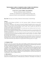
The current activities in <str<strong>on</strong>g>the</str<strong>on</strong>g> city <str<strong>on</strong>g>Baalbek</str<strong>on</strong>g> are being c<strong>on</strong>ducted in<br />
different areas <str<strong>on</strong>g>of</str<strong>on</strong>g> <str<strong>on</strong>g>the</str<strong>on</strong>g> Roman town <str<strong>on</strong>g>of</str<strong>on</strong>g> <str<strong>on</strong>g>Baalbek</str<strong>on</strong>g>. In this c<strong>on</strong>text,<br />
basically, different documentati<strong>on</strong>s, drawings and stratigraphic<br />
analyses <str<strong>on</strong>g>of</str<strong>on</strong>g> areas and buildings were achieved and discussed.<br />
The projects could be classified as following (according to Van<br />
Ess et al. 2003):<br />
- Bustan el Khan in <str<strong>on</strong>g>the</str<strong>on</strong>g> 1960s, 1970s and 2001-2004<br />
- Area <str<strong>on</strong>g>of</str<strong>on</strong>g> <str<strong>on</strong>g>the</str<strong>on</strong>g> Venus temple since 2002<br />
- Qala’a in 1960s and Sheikh Abdullah since 2002<br />
The results <str<strong>on</strong>g>of</str<strong>on</strong>g> <str<strong>on</strong>g>the</str<strong>on</strong>g> abovementi<strong>on</strong>ed works based <strong>on</strong> <str<strong>on</strong>g>the</str<strong>on</strong>g> town<br />
history and geodesy indicated some new important assumpti<strong>on</strong>s<br />
c<strong>on</strong>cerning <str<strong>on</strong>g>the</str<strong>on</strong>g> chr<strong>on</strong>ological sequences <str<strong>on</strong>g>of</str<strong>on</strong>g> <str<strong>on</strong>g>the</str<strong>on</strong>g> w<strong>on</strong>derful<br />
c<strong>on</strong>structi<strong>on</strong>s <str<strong>on</strong>g>of</str<strong>on</strong>g> <str<strong>on</strong>g>the</str<strong>on</strong>g> temples and <str<strong>on</strong>g>the</str<strong>on</strong>g>ir interrelati<strong>on</strong>ships.<br />
In <str<strong>on</strong>g>the</str<strong>on</strong>g> years (2005 and 2006) A. Klotz and M. Gessner worked<br />
<strong>on</strong>ly with <str<strong>on</strong>g>the</str<strong>on</strong>g> aerial vertical images <str<strong>on</strong>g>of</str<strong>on</strong>g> <str<strong>on</strong>g>Baalbek</str<strong>on</strong>g> to create<br />
orthophotos and rectified 2D plans. Although <str<strong>on</strong>g>the</str<strong>on</strong>g> scientific<br />
works and <str<strong>on</strong>g>the</str<strong>on</strong>g> researches in <str<strong>on</strong>g>Baalbek</str<strong>on</strong>g> started in <str<strong>on</strong>g>the</str<strong>on</strong>g> 18 th century,<br />
<str<strong>on</strong>g>the</str<strong>on</strong>g>re are many unexplained questi<strong>on</strong>s which are posed<br />
c<strong>on</strong>cerning <str<strong>on</strong>g>the</str<strong>on</strong>g> town planning and its urban progress. These<br />
questi<strong>on</strong>s are c<strong>on</strong>sidered as additi<strong>on</strong>al motivati<strong>on</strong>s for this work<br />
especially with using <str<strong>on</strong>g>the</str<strong>on</strong>g> oblique and terrestrial photos <str<strong>on</strong>g>of</str<strong>on</strong>g><br />
<str<strong>on</strong>g>Baalbek</str<strong>on</strong>g>, which could be given more informati<strong>on</strong> about <str<strong>on</strong>g>the</str<strong>on</strong>g> city.<br />
3. WORK FLOW AND RESULTS<br />
3.1. Creati<strong>on</strong> <str<strong>on</strong>g>of</str<strong>on</strong>g> Digital Terrain Model (DTM) <str<strong>on</strong>g>of</str<strong>on</strong>g> <str<strong>on</strong>g>Baalbek</str<strong>on</strong>g><br />
According to (Kö<str<strong>on</strong>g>the</str<strong>on</strong>g>, 04/2000): “Digital Elevati<strong>on</strong> Model<br />
(DEM) is <str<strong>on</strong>g>the</str<strong>on</strong>g> digital stored XYZ-triples <str<strong>on</strong>g>of</str<strong>on</strong>g> a surface. It is very<br />
necessary to menti<strong>on</strong> which surface is meant by using <str<strong>on</strong>g>the</str<strong>on</strong>g> DEM<br />
(for example: DEM <str<strong>on</strong>g>of</str<strong>on</strong>g> <str<strong>on</strong>g>the</str<strong>on</strong>g> vegetati<strong>on</strong> surface, DEM <str<strong>on</strong>g>of</str<strong>on</strong>g> <str<strong>on</strong>g>the</str<strong>on</strong>g><br />
ground water surface, DEM <str<strong>on</strong>g>of</str<strong>on</strong>g> <str<strong>on</strong>g>the</str<strong>on</strong>g> earth surface, etc.). On <str<strong>on</strong>g>the</str<strong>on</strong>g><br />
o<str<strong>on</strong>g>the</str<strong>on</strong>g>r hand <str<strong>on</strong>g>the</str<strong>on</strong>g> DTM is <str<strong>on</strong>g>the</str<strong>on</strong>g> digital stored XYZ-triples <str<strong>on</strong>g>of</str<strong>on</strong>g> <str<strong>on</strong>g>the</str<strong>on</strong>g><br />
earth surface, <str<strong>on</strong>g>the</str<strong>on</strong>g>refore <str<strong>on</strong>g>the</str<strong>on</strong>g> DTM is c<strong>on</strong>sidered, in practice, as<br />
<strong>on</strong>e special case <str<strong>on</strong>g>of</str<strong>on</strong>g> <str<strong>on</strong>g>the</str<strong>on</strong>g> DEM; that means DTM = DEM <str<strong>on</strong>g>of</str<strong>on</strong>g> <str<strong>on</strong>g>the</str<strong>on</strong>g><br />
earth surface”.<br />
Basically, we c<strong>on</strong>cern <str<strong>on</strong>g>the</str<strong>on</strong>g> height values <str<strong>on</strong>g>of</str<strong>on</strong>g> <str<strong>on</strong>g>the</str<strong>on</strong>g> ground by using a<br />
DTM. In <str<strong>on</strong>g>the</str<strong>on</strong>g> case <str<strong>on</strong>g>of</str<strong>on</strong>g> evaluati<strong>on</strong> <str<strong>on</strong>g>of</str<strong>on</strong>g> digital images <str<strong>on</strong>g>the</str<strong>on</strong>g> height<br />
differences <str<strong>on</strong>g>of</str<strong>on</strong>g> <str<strong>on</strong>g>the</str<strong>on</strong>g> earth surface will lead to radial distorti<strong>on</strong>s.<br />
These distorti<strong>on</strong>s could be minimized in <str<strong>on</strong>g>the</str<strong>on</strong>g> digital images by<br />
using a DTM.<br />
2<br />
In practice, a generati<strong>on</strong> <str<strong>on</strong>g>of</str<strong>on</strong>g> DTMs depends mainly <strong>on</strong> <str<strong>on</strong>g>the</str<strong>on</strong>g> input<br />
data (e.g. oriented digital images, topographical maps which<br />
should cover <str<strong>on</strong>g>the</str<strong>on</strong>g> whole area <str<strong>on</strong>g>of</str<strong>on</strong>g> interest, etc.). Depending <strong>on</strong> <str<strong>on</strong>g>the</str<strong>on</strong>g><br />
<str<strong>on</strong>g>Baalbek</str<strong>on</strong>g>’s aerial images (vertical images type) it was difficult to<br />
create a well quality DTM from <str<strong>on</strong>g>the</str<strong>on</strong>g> oriented images, because<br />
<str<strong>on</strong>g>the</str<strong>on</strong>g>y do not have a good state due to <str<strong>on</strong>g>the</str<strong>on</strong>g>ir poor properties.<br />
Therefore, a DTM was generated using topographical maps <str<strong>on</strong>g>of</str<strong>on</strong>g><br />
<str<strong>on</strong>g>Baalbek</str<strong>on</strong>g>. However, <str<strong>on</strong>g>the</str<strong>on</strong>g>re are two topographical maps <str<strong>on</strong>g>of</str<strong>on</strong>g><br />
<str<strong>on</strong>g>Baalbek</str<strong>on</strong>g> which were obtained from <str<strong>on</strong>g>the</str<strong>on</strong>g> institute <str<strong>on</strong>g>of</str<strong>on</strong>g> Francais du<br />
Proche Orient (IFPO) in Damascus. Both maps were scanned<br />
with <str<strong>on</strong>g>the</str<strong>on</strong>g> scan resoluti<strong>on</strong> (300 dpi). The Properties <str<strong>on</strong>g>of</str<strong>on</strong>g> <str<strong>on</strong>g>Baalbek</str<strong>on</strong>g>’s<br />
maps implemented can be expressed as following:<br />
• Emissi<strong>on</strong> date is in <str<strong>on</strong>g>the</str<strong>on</strong>g> year 1962<br />
• The maps cover <str<strong>on</strong>g>the</str<strong>on</strong>g> whole area <str<strong>on</strong>g>of</str<strong>on</strong>g> <str<strong>on</strong>g>Baalbek</str<strong>on</strong>g><br />
• They have <str<strong>on</strong>g>the</str<strong>on</strong>g> scale (1: 20 000)<br />
• Ground resoluti<strong>on</strong> is ca. 1.7 m (with respect to pixel size)<br />
• Ellipsoid used is Clark 1880<br />
• Maps’ projecti<strong>on</strong> is stereographic<br />
• The interval <str<strong>on</strong>g>of</str<strong>on</strong>g> c<strong>on</strong>tour lines is 10 m<br />
• L<strong>on</strong>gitude line is 38°<br />
• Latitude line is 43° 50´<br />
In order to focus <strong>on</strong>ly <strong>on</strong> <str<strong>on</strong>g>the</str<strong>on</strong>g> same area appearing in <str<strong>on</strong>g>the</str<strong>on</strong>g> vertical<br />
images type <str<strong>on</strong>g>of</str<strong>on</strong>g> <str<strong>on</strong>g>Baalbek</str<strong>on</strong>g> a new map was derived based <strong>on</strong> <str<strong>on</strong>g>the</str<strong>on</strong>g><br />
abovementi<strong>on</strong>ed topographic maps. This map is indicated with<br />
<str<strong>on</strong>g>the</str<strong>on</strong>g> name submap_baalbek. The derived map should be<br />
georeferenced <strong>on</strong>to <str<strong>on</strong>g>the</str<strong>on</strong>g> local system <str<strong>on</strong>g>of</str<strong>on</strong>g> <str<strong>on</strong>g>Baalbek</str<strong>on</strong>g>’s vertical<br />
images; that means <str<strong>on</strong>g>the</str<strong>on</strong>g> new map should be associated with <str<strong>on</strong>g>the</str<strong>on</strong>g><br />
vertical image coordinate system (<str<strong>on</strong>g>Baalbek</str<strong>on</strong>g>’s local system).<br />
Geometric C<strong>on</strong>trol Points (GCPs) take an important role in <str<strong>on</strong>g>the</str<strong>on</strong>g><br />
georeference process in order to enforce <str<strong>on</strong>g>the</str<strong>on</strong>g> transformati<strong>on</strong><br />
between <str<strong>on</strong>g>the</str<strong>on</strong>g> map and <str<strong>on</strong>g>the</str<strong>on</strong>g> images. The critic number (n) <str<strong>on</strong>g>of</str<strong>on</strong>g> GCPs<br />
requested depends <strong>on</strong> <str<strong>on</strong>g>the</str<strong>on</strong>g> order <str<strong>on</strong>g>of</str<strong>on</strong>g> <str<strong>on</strong>g>the</str<strong>on</strong>g> transformati<strong>on</strong>. This<br />
number is given (Leica Geosystems, 2005):<br />
( t + 1)(<br />
t + 2)<br />
n =<br />
(1)<br />
2<br />
where: t is <str<strong>on</strong>g>the</str<strong>on</strong>g> order <str<strong>on</strong>g>of</str<strong>on</strong>g> <str<strong>on</strong>g>the</str<strong>on</strong>g> transformati<strong>on</strong><br />
If <str<strong>on</strong>g>the</str<strong>on</strong>g> minimum number <str<strong>on</strong>g>of</str<strong>on</strong>g> <str<strong>on</strong>g>the</str<strong>on</strong>g> GCPs is not satisfied, it will not<br />
be possible to resample <str<strong>on</strong>g>the</str<strong>on</strong>g> input data (<str<strong>on</strong>g>Baalbek</str<strong>on</strong>g>’s map); this<br />
means <str<strong>on</strong>g>the</str<strong>on</strong>g> georeference process will not be executed. In our<br />
case eight GCPs were applied into <str<strong>on</strong>g>the</str<strong>on</strong>g> process and <str<strong>on</strong>g>the</str<strong>on</strong>g> resample<br />
method selected was “Nearest Neighbour”. The map resulted<br />
has <str<strong>on</strong>g>the</str<strong>on</strong>g> output cell size ca. (0.98 m) for X and Y. The next step<br />
is <str<strong>on</strong>g>the</str<strong>on</strong>g> vector process with it <str<strong>on</strong>g>the</str<strong>on</strong>g> c<strong>on</strong>tour lines were digitalized<br />
using <str<strong>on</strong>g>the</str<strong>on</strong>g> vector tools which are based <strong>on</strong> <str<strong>on</strong>g>the</str<strong>on</strong>g> ESRI 1 data<br />
models. Through <str<strong>on</strong>g>the</str<strong>on</strong>g> digitalizati<strong>on</strong> process <str<strong>on</strong>g>the</str<strong>on</strong>g> c<strong>on</strong>tour lines<br />
interval was preserved as (10) m. The height values <str<strong>on</strong>g>of</str<strong>on</strong>g> <str<strong>on</strong>g>the</str<strong>on</strong>g><br />
c<strong>on</strong>tour lines (regard to <str<strong>on</strong>g>the</str<strong>on</strong>g> new resampled map) are in <str<strong>on</strong>g>the</str<strong>on</strong>g><br />
range (1080-1450 m).<br />
The surfacing process was performed successfully and <str<strong>on</strong>g>the</str<strong>on</strong>g> DTM<br />
<str<strong>on</strong>g>of</str<strong>on</strong>g> <str<strong>on</strong>g>Baalbek</str<strong>on</strong>g> was generated (a secti<strong>on</strong> <str<strong>on</strong>g>of</str<strong>on</strong>g> <str<strong>on</strong>g>Baalbek</str<strong>on</strong>g>’s DTM created<br />
is shown in <str<strong>on</strong>g>the</str<strong>on</strong>g> Figure 1). The DTM properties could be<br />
summarized as following:<br />
• Output file name: dgm_karte_lokal<br />
• Cell size for X and Y is 9.00 m<br />
1 ESRI: Envir<strong>on</strong>mental Systems Research Institute
• The coordinates <str<strong>on</strong>g>of</str<strong>on</strong>g> <str<strong>on</strong>g>the</str<strong>on</strong>g> upper left point: X=7605.35 m and<br />
Y=12298.39 m (in <str<strong>on</strong>g>Baalbek</str<strong>on</strong>g>’s local system)<br />
• The coordinates <str<strong>on</strong>g>of</str<strong>on</strong>g> <str<strong>on</strong>g>the</str<strong>on</strong>g> lower right point: X=12534.97 m and<br />
Y=8313.97 m (in <str<strong>on</strong>g>Baalbek</str<strong>on</strong>g>’s local system)<br />
Fig. 1: A secti<strong>on</strong> <str<strong>on</strong>g>of</str<strong>on</strong>g> <str<strong>on</strong>g>Baalbek</str<strong>on</strong>g>’s DTM (Height values in m)<br />
3.2. <str<strong>on</strong>g>Baalbek</str<strong>on</strong>g> orthophotos’ generati<strong>on</strong><br />
3.2.1. Definiti<strong>on</strong><br />
An orthophoto is an image transformed geometrically; this<br />
transformati<strong>on</strong> c<strong>on</strong>verts <str<strong>on</strong>g>the</str<strong>on</strong>g> original photo, which is in general<br />
distorted, into orthog<strong>on</strong>al projecti<strong>on</strong>. The orthog<strong>on</strong>al projecti<strong>on</strong><br />
<str<strong>on</strong>g>of</str<strong>on</strong>g> an image enables to display <str<strong>on</strong>g>the</str<strong>on</strong>g> object surface included in<br />
this image in an orthog<strong>on</strong>al view.<br />
The aforementi<strong>on</strong>ed transformati<strong>on</strong> process is called “image<br />
rectificati<strong>on</strong>”. The rectificati<strong>on</strong> process could be classified into<br />
planar or differential rectificati<strong>on</strong>. In our case <str<strong>on</strong>g>the</str<strong>on</strong>g> sec<strong>on</strong>d <strong>on</strong>e is<br />
requested, because <str<strong>on</strong>g>the</str<strong>on</strong>g> height differences <str<strong>on</strong>g>of</str<strong>on</strong>g> <str<strong>on</strong>g>the</str<strong>on</strong>g> object points (or<br />
c<strong>on</strong>trol points) exceed <str<strong>on</strong>g>the</str<strong>on</strong>g> critic value ∆hmax which is calculated<br />
as following (Wiedemann, 2004):<br />
∆h max =<br />
ck ∆r max (2)<br />
r'max<br />
where: ∆rmax …. maximal distorti<strong>on</strong><br />
max r′ …….maximal radius <str<strong>on</strong>g>of</str<strong>on</strong>g> <str<strong>on</strong>g>the</str<strong>on</strong>g> image<br />
……... focal length<br />
3.2.2. Orthophotos creati<strong>on</strong> using LPS<br />
Leica Photogrammetry Suite (LPS) is defined as a collecti<strong>on</strong> <str<strong>on</strong>g>of</str<strong>on</strong>g><br />
integrated s<str<strong>on</strong>g>of</str<strong>on</strong>g>tware tools which <str<strong>on</strong>g>of</str<strong>on</strong>g>fer different photogrammetric<br />
processes (e.g. an orthophoto creati<strong>on</strong>, etc.) for <str<strong>on</strong>g>the</str<strong>on</strong>g> geospatial<br />
imaging applicati<strong>on</strong>s. The primary comp<strong>on</strong>ent <str<strong>on</strong>g>of</str<strong>on</strong>g> LPS is “LPS<br />
Project Manager” which reduces <str<strong>on</strong>g>the</str<strong>on</strong>g> cost and time associated<br />
with different photogrammetrical procedures (more details are<br />
presented in LPS user’s guide, Leica Geosystems, 2005).<br />
The vertical images used (in this step, seven vertical images)<br />
were saved in <str<strong>on</strong>g>the</str<strong>on</strong>g> block file “<str<strong>on</strong>g>Baalbek</str<strong>on</strong>g>.blk”. Orthophotos <str<strong>on</strong>g>of</str<strong>on</strong>g> <str<strong>on</strong>g>the</str<strong>on</strong>g><br />
oriented images - associated with <str<strong>on</strong>g>the</str<strong>on</strong>g> block file “<str<strong>on</strong>g>Baalbek</str<strong>on</strong>g>.blk”-<br />
were generated with respect to <str<strong>on</strong>g>the</str<strong>on</strong>g> orientati<strong>on</strong> parameters<br />
estimated <strong>on</strong> <strong>on</strong>e hand (Alamouri et al., 2008) and to <str<strong>on</strong>g>the</str<strong>on</strong>g><br />
generated DTM in o<str<strong>on</strong>g>the</str<strong>on</strong>g>r hand. The cell size <str<strong>on</strong>g>of</str<strong>on</strong>g> <str<strong>on</strong>g>the</str<strong>on</strong>g> orthophotos<br />
was computed automatically based <strong>on</strong> <str<strong>on</strong>g>the</str<strong>on</strong>g> scale and resoluti<strong>on</strong><br />
<str<strong>on</strong>g>of</str<strong>on</strong>g> <str<strong>on</strong>g>the</str<strong>on</strong>g> images; in this c<strong>on</strong>text, <str<strong>on</strong>g>the</str<strong>on</strong>g> cell size is approximately<br />
bounded to 0.13 m for X and Y. The resample method “Bilinear<br />
3<br />
Interpolati<strong>on</strong>” was implemented due to <str<strong>on</strong>g>the</str<strong>on</strong>g> well quality <str<strong>on</strong>g>of</str<strong>on</strong>g> <str<strong>on</strong>g>the</str<strong>on</strong>g><br />
gray values’ calculati<strong>on</strong>. By this method <str<strong>on</strong>g>the</str<strong>on</strong>g> requested gray<br />
value <str<strong>on</strong>g>of</str<strong>on</strong>g> a pixel in <str<strong>on</strong>g>the</str<strong>on</strong>g> output image is computed building <strong>on</strong> <str<strong>on</strong>g>the</str<strong>on</strong>g><br />
four nearest neighbours (four nearest pixels, Fig. 2). The new<br />
gray value (g) is calculated based <strong>on</strong> <str<strong>on</strong>g>the</str<strong>on</strong>g> gray values g 1, g 2, g 3<br />
and g 4. It is given (Pum, 2003 & Luhmann, 2003):<br />
g = g1<br />
+ dx(<br />
g2<br />
− g1)<br />
+ dy(<br />
g3<br />
− g1)<br />
+ dx ⋅dy<br />
g − g − g + g )<br />
(3)<br />
( 4 2 3 1<br />
Fig. 2: The principle <str<strong>on</strong>g>of</str<strong>on</strong>g> <str<strong>on</strong>g>the</str<strong>on</strong>g> bilinear interpolati<strong>on</strong><br />
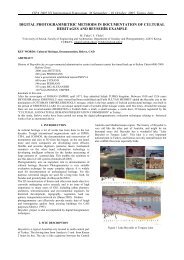
The Figure (3) shows two original vertical images and <str<strong>on</strong>g>the</str<strong>on</strong>g>ir<br />
orthophotos created; (a: original image 1981, b: orthophoto<br />
1981, c: original image 2025 and d: orthophoto 2025).<br />
Fig. 3: Two original vertical images <str<strong>on</strong>g>of</str<strong>on</strong>g> <str<strong>on</strong>g>Baalbek</str<strong>on</strong>g> (left) and <str<strong>on</strong>g>the</str<strong>on</strong>g>ir<br />
orthophotos generated (right)<br />
3.3. Regi<strong>on</strong> mosaic creati<strong>on</strong><br />
“The term mosaic can be defined as <str<strong>on</strong>g>the</str<strong>on</strong>g> m<strong>on</strong>tage process <str<strong>on</strong>g>of</str<strong>on</strong>g><br />
multiple rectified images (multi-orthophotos) in order to merge<br />
<str<strong>on</strong>g>the</str<strong>on</strong>g>m in uniform image” (Wiedemann, 2004). In this c<strong>on</strong>text;<br />
<str<strong>on</strong>g>the</str<strong>on</strong>g> geometric and radiometric adjustment <str<strong>on</strong>g>of</str<strong>on</strong>g> orthophotos has to<br />
be taken into <str<strong>on</strong>g>the</str<strong>on</strong>g> c<strong>on</strong>siderati<strong>on</strong>.<br />
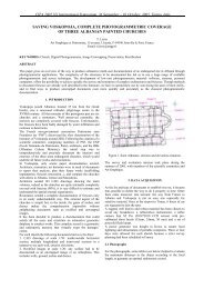
The main task in this step is <str<strong>on</strong>g>the</str<strong>on</strong>g> generati<strong>on</strong> <str<strong>on</strong>g>of</str<strong>on</strong>g> <str<strong>on</strong>g>the</str<strong>on</strong>g> cut lines<br />
between <str<strong>on</strong>g>the</str<strong>on</strong>g> orthophotos used. Cut lines performance depends<br />
<strong>on</strong> <str<strong>on</strong>g>the</str<strong>on</strong>g> overlaying between <str<strong>on</strong>g>the</str<strong>on</strong>g> images. N<strong>on</strong>-planar objects in <str<strong>on</strong>g>the</str<strong>on</strong>g><br />
rectified images, in additi<strong>on</strong>, <str<strong>on</strong>g>the</str<strong>on</strong>g> image noise led to challenges<br />
through <str<strong>on</strong>g>the</str<strong>on</strong>g> overlaying between <str<strong>on</strong>g>the</str<strong>on</strong>g> historical images (e.g.<br />
objects matching and recogniti<strong>on</strong>, etc.). To define cut lines in an<br />
optimal way, a digitizing approach (semi-automatic) was used.<br />
An example <str<strong>on</strong>g>of</str<strong>on</strong>g> adjusted cut lines is presented in <str<strong>on</strong>g>the</str<strong>on</strong>g> Figure (4).
On <str<strong>on</strong>g>the</str<strong>on</strong>g> o<str<strong>on</strong>g>the</str<strong>on</strong>g>r hhand<br />
<str<strong>on</strong>g>the</str<strong>on</strong>g> histogrram<br />
matching aapproach<br />
was ussed<br />
to<br />
adjust <str<strong>on</strong>g>the</str<strong>on</strong>g> radiiometric<br />
failurees<br />
(noise, c<strong>on</strong>traast,<br />
brightness, etc.);<br />
so that <str<strong>on</strong>g>the</str<strong>on</strong>g> (orrthophoto<br />
-19855)<br />
was implemeented<br />
as a mustter<br />
for<br />
<str<strong>on</strong>g>the</str<strong>on</strong>g> gray valuees<br />
transformatii<strong>on</strong><br />
<str<strong>on</strong>g>of</str<strong>on</strong>g> orthophootos<br />
into <str<strong>on</strong>g>the</str<strong>on</strong>g> rregi<strong>on</strong><br />
mosaic (gray values adjustmment).<br />
An illusttrati<strong>on</strong><br />
<str<strong>on</strong>g>of</str<strong>on</strong>g> Baallbek’s<br />
mosaic based <strong>on</strong> <str<strong>on</strong>g>the</str<strong>on</strong>g> orthophootos<br />
is shown inn<br />
(Figure 5).<br />
Fig. 4: A secti<strong>on</strong> <str<strong>on</strong>g>of</str<strong>on</strong>g> threee<br />
cut lines creaated<br />
between 3<br />
orthophootos<br />
<str<strong>on</strong>g>of</str<strong>on</strong>g> <str<strong>on</strong>g>Baalbek</str<strong>on</strong>g>k<br />
Fig. 5: B<str<strong>on</strong>g>Baalbek</str<strong>on</strong>g>’s<br />
mosaaic<br />
based <strong>on</strong> sevven<br />
orthophos<br />
3.4. Features acquisiti<strong>on</strong> annd<br />
fusi<strong>on</strong><br />
3.4.1. Extractti<strong>on</strong><br />
<str<strong>on</strong>g>of</str<strong>on</strong>g> 2D objeects<br />
<str<strong>on</strong>g>Baalbek</str<strong>on</strong>g>’s mossaic<br />
created waas<br />
regarded a baasic<br />
source to extract<br />
2D coordinatees<br />
<str<strong>on</strong>g>of</str<strong>on</strong>g> requested objects. In ourr<br />
project <str<strong>on</strong>g>the</str<strong>on</strong>g> moost<br />
<str<strong>on</strong>g>of</str<strong>on</strong>g><br />
objects (incluuded<br />
in imagess)<br />
are buildinggs,<br />
<str<strong>on</strong>g>the</str<strong>on</strong>g>refore itt<br />
was<br />
easier to exprress<br />
<str<strong>on</strong>g>the</str<strong>on</strong>g>se buildings<br />
(also soome<br />
streets, rooutes)<br />
through polygg<strong>on</strong><br />
(or multiplle<br />
polyg<strong>on</strong>s) annd<br />
save it as vvector<br />
data (Figure 6). The vectoor<br />
tools are baased<br />
<strong>on</strong> ESRI data<br />
models, <str<strong>on</strong>g>the</str<strong>on</strong>g>reefore<br />
ESRI shaape<br />
files can bbe<br />
used for fuur<str<strong>on</strong>g>the</str<strong>on</strong>g>r<br />
works withouut<br />
c<strong>on</strong>versi<strong>on</strong>. Each vector layer has attriibutes<br />
which includee<br />
different paraameters<br />
(for e. .g. area <str<strong>on</strong>g>of</str<strong>on</strong>g> polyg<strong>on</strong>,<br />
perimeter <str<strong>on</strong>g>of</str<strong>on</strong>g> a polyg<strong>on</strong>). Thhe<br />
n<strong>on</strong>-buildingg<br />
objects (e.g. trees,<br />
vegetati<strong>on</strong>) caan<br />
be modelledd<br />
as discrete pooints.<br />
The distinncti<strong>on</strong><br />
4<br />
<str<strong>on</strong>g>of</str<strong>on</strong>g> ob bjects in <str<strong>on</strong>g>the</str<strong>on</strong>g> mosaic<br />
was <str<strong>on</strong>g>the</str<strong>on</strong>g> mmain<br />
problem in i <str<strong>on</strong>g>the</str<strong>on</strong>g> features’<br />
acqu uisiti<strong>on</strong> process because <str<strong>on</strong>g>of</str<strong>on</strong>g> <str<strong>on</strong>g>the</str<strong>on</strong>g> high noise and d c<strong>on</strong>trast in <str<strong>on</strong>g>the</str<strong>on</strong>g>e<br />
imag ges <str<strong>on</strong>g>of</str<strong>on</strong>g> <str<strong>on</strong>g>Baalbek</str<strong>on</strong>g>.<br />
Fig. 6: 2D daata<br />
<str<strong>on</strong>g>of</str<strong>on</strong>g> extractedd<br />
buildings (shap pe-data)<br />
3.4.2 2. Integrati<strong>on</strong> o<str<strong>on</strong>g>of</str<strong>on</strong>g><br />
height valuees<br />
For each e 2D object extracted <str<strong>on</strong>g>the</str<strong>on</strong>g>ree<br />
is a Z-value associated a with. .<br />
In ot <str<strong>on</strong>g>the</str<strong>on</strong>g>r words, eacch<br />
Z-value is ggiven<br />
as a func cti<strong>on</strong> <str<strong>on</strong>g>of</str<strong>on</strong>g> <str<strong>on</strong>g>the</str<strong>on</strong>g> 2DD<br />
posit ti<strong>on</strong> with <str<strong>on</strong>g>the</str<strong>on</strong>g> assumpti<strong>on</strong><br />
thatt<br />
a polyg<strong>on</strong> (i) has <str<strong>on</strong>g>the</str<strong>on</strong>g> heightt<br />
value e Zci related to t<str<strong>on</strong>g>the</str<strong>on</strong>g><br />
polyg<strong>on</strong> cenntroid<br />
(Xci, Yci) ):<br />
ZZc<br />
i = Z(<br />
Xci<br />
, Yc i )<br />
How wever, two apprroaches<br />
were uused<br />
to determ mine <str<strong>on</strong>g>the</str<strong>on</strong>g> heightt<br />
value es. The first is bbased<br />
<strong>on</strong> <str<strong>on</strong>g>the</str<strong>on</strong>g> orriented<br />
model <str<strong>on</strong>g>of</str<strong>on</strong>g> o <str<strong>on</strong>g>the</str<strong>on</strong>g> terrestriall<br />
and oblique o images <str<strong>on</strong>g>of</str<strong>on</strong>g> <str<strong>on</strong>g>Baalbek</str<strong>on</strong>g>, whhereas<br />
a geome etric positi<strong>on</strong> <str<strong>on</strong>g>of</str<strong>on</strong>g>f<br />
an im mage point exissting<br />
at least inn<br />
two oriented images can bee<br />
deter rmined using thhe<br />
Epipolar Geoometry<br />
(Rodeho orst, 2004). Ann<br />
intersecti<strong>on</strong><br />
<str<strong>on</strong>g>of</str<strong>on</strong>g> at least two EEpipolar<br />
lines in an imagee<br />
deter rmines <str<strong>on</strong>g>the</str<strong>on</strong>g> positti<strong>on</strong><br />
<str<strong>on</strong>g>of</str<strong>on</strong>g> a requessted<br />
image poin nt as well as <str<strong>on</strong>g>the</str<strong>on</strong>g>e<br />
<str<strong>on</strong>g>3D</str<strong>on</strong>g> coordinates c assoociated<br />
with (Fiig.<br />
7).<br />
The sec<strong>on</strong>d <strong>on</strong>e is t<str<strong>on</strong>g>the</str<strong>on</strong>g><br />
stereoscopicc<br />
analysis which<br />
enables us too<br />
obtai in height valuees<br />
using a pair images oriented.<br />
Due to <str<strong>on</strong>g>the</str<strong>on</strong>g>e<br />
poor properties <str<strong>on</strong>g>of</str<strong>on</strong>g> B<str<strong>on</strong>g>Baalbek</str<strong>on</strong>g>’s<br />
imagges<br />
it was diffic cult to certain a<br />
point t positi<strong>on</strong> in ann<br />
image pair sellected<br />
exactly. This challengee<br />
led to t a point displlacement<br />
whichh<br />
affects <str<strong>on</strong>g>the</str<strong>on</strong>g> de eterminati<strong>on</strong> <str<strong>on</strong>g>of</str<strong>on</strong>g>f<br />
heigh ht values. Figuure<br />
(8) displayys<br />
<str<strong>on</strong>g>the</str<strong>on</strong>g> Digital Stereo Modell<br />
(DSM M) created baseed<br />
<strong>on</strong> a selected<br />
oriented pair r <str<strong>on</strong>g>of</str<strong>on</strong>g> <str<strong>on</strong>g>the</str<strong>on</strong>g> verticall<br />
imag ges <str<strong>on</strong>g>of</str<strong>on</strong>g> <str<strong>on</strong>g>Baalbek</str<strong>on</strong>g>.<br />
Fig. F 7: Determiinati<strong>on</strong><br />
<str<strong>on</strong>g>of</str<strong>on</strong>g> <str<strong>on</strong>g>the</str<strong>on</strong>g> pooint<br />
positi<strong>on</strong> ba ased <strong>on</strong> <str<strong>on</strong>g>the</str<strong>on</strong>g><br />
inntersecti<strong>on</strong><br />
<str<strong>on</strong>g>of</str<strong>on</strong>g> Eppipolar<br />
lines<br />
(4)
Fig. 8: Digital Stereo Model based <strong>on</strong> pair images <str<strong>on</strong>g>of</str<strong>on</strong>g> <str<strong>on</strong>g>Baalbek</str<strong>on</strong>g><br />
3.5. Classificati<strong>on</strong> <str<strong>on</strong>g>of</str<strong>on</strong>g> applicable <str<strong>on</strong>g>3D</str<strong>on</strong>g> object points<br />
An important task <str<strong>on</strong>g>of</str<strong>on</strong>g> this work is a creati<strong>on</strong> <str<strong>on</strong>g>of</str<strong>on</strong>g> applicable <str<strong>on</strong>g>3D</str<strong>on</strong>g><br />
points’ classificati<strong>on</strong>. It will enable us to know: from which<br />
camera an object point is taken as well as from which photo this<br />
point is optimal shown. This classificati<strong>on</strong> is necessary for o<str<strong>on</strong>g>the</str<strong>on</strong>g>r<br />
applicati<strong>on</strong>s (e.g. GIS, architecture, etc.).<br />
The principle <str<strong>on</strong>g>of</str<strong>on</strong>g> this classificati<strong>on</strong> intended could be classified<br />
into following steps:<br />
• Identificati<strong>on</strong> <str<strong>on</strong>g>of</str<strong>on</strong>g> a <str<strong>on</strong>g>3D</str<strong>on</strong>g> object point locati<strong>on</strong>; that means in<br />
which image/s <str<strong>on</strong>g>the</str<strong>on</strong>g> point requested exists (Figure 9, a).<br />
• Estimati<strong>on</strong> <str<strong>on</strong>g>of</str<strong>on</strong>g> <str<strong>on</strong>g>the</str<strong>on</strong>g> standard deviati<strong>on</strong>s ( , and ) for<br />
<str<strong>on</strong>g>the</str<strong>on</strong>g> object point coordinates (Xi, Y i and Z i). The General<br />
Estimated Standard Deviati<strong>on</strong>s (GESDi = S i, Fig. 9, b) can<br />
be expressed:<br />
<br />
(5)<br />
where: i=1,…n; n number <str<strong>on</strong>g>of</str<strong>on</strong>g> applicable object points<br />
Fig. 9: classificati<strong>on</strong> principle <str<strong>on</strong>g>of</str<strong>on</strong>g> <str<strong>on</strong>g>3D</str<strong>on</strong>g> applicable points<br />
5<br />
The image index (ID) as well as image types (in this case: V =<br />
vertical, O = oblique and T= terrestrial) should be taken into <str<strong>on</strong>g>the</str<strong>on</strong>g><br />
account. Therefore, <str<strong>on</strong>g>the</str<strong>on</strong>g> formula (5) could be given:<br />
<br />
(6)<br />
where: j is <str<strong>on</strong>g>the</str<strong>on</strong>g> image_ID and k is <str<strong>on</strong>g>the</str<strong>on</strong>g> image type<br />
• <str<strong>on</strong>g>Based</str<strong>on</strong>g> <strong>on</strong> <str<strong>on</strong>g>the</str<strong>on</strong>g> minimum value <str<strong>on</strong>g>of</str<strong>on</strong>g> <str<strong>on</strong>g>the</str<strong>on</strong>g> S i(kj) we can know that<br />
<str<strong>on</strong>g>the</str<strong>on</strong>g> object point (Pi) is optimally shown in <str<strong>on</strong>g>the</str<strong>on</strong>g> image which<br />
has an ID = j as well as <str<strong>on</strong>g>the</str<strong>on</strong>g> type (k).<br />
4. RESULTS QUALITY AND INTERPRETATION<br />
4.1. <str<strong>on</strong>g>Baalbek</str<strong>on</strong>g> DTM quality<br />
“The grid cell size is <str<strong>on</strong>g>the</str<strong>on</strong>g> most comm<strong>on</strong> criteri<strong>on</strong> c<strong>on</strong>cerning <str<strong>on</strong>g>the</str<strong>on</strong>g><br />
quality <str<strong>on</strong>g>of</str<strong>on</strong>g> <str<strong>on</strong>g>the</str<strong>on</strong>g> DTM. An increasing <str<strong>on</strong>g>of</str<strong>on</strong>g> <str<strong>on</strong>g>the</str<strong>on</strong>g> grid cell size leads to a<br />
decreasing <str<strong>on</strong>g>of</str<strong>on</strong>g> DTM resoluti<strong>on</strong> that means an increasing <str<strong>on</strong>g>of</str<strong>on</strong>g> <str<strong>on</strong>g>the</str<strong>on</strong>g><br />
generalizati<strong>on</strong> <str<strong>on</strong>g>of</str<strong>on</strong>g> <str<strong>on</strong>g>the</str<strong>on</strong>g> real surface. The DTM precisi<strong>on</strong> with<br />
respect to <str<strong>on</strong>g>the</str<strong>on</strong>g> grid cell size and its altitude depends <strong>on</strong> <str<strong>on</strong>g>the</str<strong>on</strong>g> slope<br />
gradient <str<strong>on</strong>g>of</str<strong>on</strong>g> <str<strong>on</strong>g>the</str<strong>on</strong>g> real surface and <str<strong>on</strong>g>the</str<strong>on</strong>g> size <str<strong>on</strong>g>of</str<strong>on</strong>g> <str<strong>on</strong>g>the</str<strong>on</strong>g> terrain unit. The<br />
DTM will be accurate created, if <str<strong>on</strong>g>the</str<strong>on</strong>g> real surface is steep and <str<strong>on</strong>g>the</str<strong>on</strong>g><br />
terrain units are small. Units smaller than <str<strong>on</strong>g>the</str<strong>on</strong>g> grid cell size will<br />
not visible in <str<strong>on</strong>g>the</str<strong>on</strong>g> DTM because <str<strong>on</strong>g>the</str<strong>on</strong>g>y just slip through <str<strong>on</strong>g>the</str<strong>on</strong>g> grid”<br />
(Kö<str<strong>on</strong>g>the</str<strong>on</strong>g>, 04/2000). The ground resoluti<strong>on</strong> <str<strong>on</strong>g>of</str<strong>on</strong>g> <str<strong>on</strong>g>the</str<strong>on</strong>g> input data<br />
(map/image) takes an important role in <str<strong>on</strong>g>the</str<strong>on</strong>g> calculati<strong>on</strong> <str<strong>on</strong>g>of</str<strong>on</strong>g> <str<strong>on</strong>g>the</str<strong>on</strong>g><br />
DTM grid cell size. With respect to <str<strong>on</strong>g>the</str<strong>on</strong>g> assumpti<strong>on</strong> that <str<strong>on</strong>g>the</str<strong>on</strong>g> grid<br />
cell size computati<strong>on</strong> based <strong>on</strong> a 1 pixel to 10 pixels in <str<strong>on</strong>g>the</str<strong>on</strong>g><br />
DTM, that means <str<strong>on</strong>g>the</str<strong>on</strong>g> ground resoluti<strong>on</strong> <str<strong>on</strong>g>of</str<strong>on</strong>g> 1 meter leads to cell<br />
size for <str<strong>on</strong>g>the</str<strong>on</strong>g> DTM <str<strong>on</strong>g>of</str<strong>on</strong>g> 10 meters. The ground resoluti<strong>on</strong> <str<strong>on</strong>g>of</str<strong>on</strong>g><br />
<str<strong>on</strong>g>Baalbek</str<strong>on</strong>g>’s map is ca. <str<strong>on</strong>g>of</str<strong>on</strong>g> (1.7) m which leads to an appropriate<br />
critic cell size <str<strong>on</strong>g>of</str<strong>on</strong>g> (17) m, <str<strong>on</strong>g>the</str<strong>on</strong>g>refore <str<strong>on</strong>g>the</str<strong>on</strong>g> assumed cell size <str<strong>on</strong>g>of</str<strong>on</strong>g> <str<strong>on</strong>g>the</str<strong>on</strong>g><br />
DTM has not to exceed <str<strong>on</strong>g>the</str<strong>on</strong>g> critic value (17) m. In our case, <str<strong>on</strong>g>the</str<strong>on</strong>g><br />
applied cell size is (9) m and this reveals that <str<strong>on</strong>g>the</str<strong>on</strong>g> generalizati<strong>on</strong><br />
<str<strong>on</strong>g>of</str<strong>on</strong>g> <str<strong>on</strong>g>the</str<strong>on</strong>g> real surface throughout <str<strong>on</strong>g>the</str<strong>on</strong>g> model was relative decreased.<br />
O<str<strong>on</strong>g>the</str<strong>on</strong>g>r c<strong>on</strong>trol <str<strong>on</strong>g>of</str<strong>on</strong>g> <str<strong>on</strong>g>the</str<strong>on</strong>g> generated DTM quality is <str<strong>on</strong>g>the</str<strong>on</strong>g> creati<strong>on</strong> <str<strong>on</strong>g>of</str<strong>on</strong>g> a<br />
new c<strong>on</strong>tour map as (Point Status Output Image PSOI, shape<br />
file) using <str<strong>on</strong>g>the</str<strong>on</strong>g> DTM created. The PSOI illustrates <str<strong>on</strong>g>the</str<strong>on</strong>g> quality<br />
associated with <str<strong>on</strong>g>the</str<strong>on</strong>g> correlated DTM postings which are<br />
classified in: Excellent, Good, Fair, Isolated or Suspicious. By<br />
comparing between <str<strong>on</strong>g>the</str<strong>on</strong>g> PSOI and <str<strong>on</strong>g>the</str<strong>on</strong>g> digitized c<strong>on</strong>tour lines, we<br />
could be accepted that <str<strong>on</strong>g>the</str<strong>on</strong>g> both are approximately well matched<br />
(Figure 10); that means <str<strong>on</strong>g>the</str<strong>on</strong>g> DTM posting can be categorized as<br />
good, <str<strong>on</strong>g>the</str<strong>on</strong>g>refore it was possible to use it in orthophotos creati<strong>on</strong>.<br />
Fig. 10: Comparing between digitized c<strong>on</strong>tour lines and <str<strong>on</strong>g>the</str<strong>on</strong>g> new<br />
<strong>on</strong>e created using <str<strong>on</strong>g>the</str<strong>on</strong>g> DTM-status image points
4.2. <str<strong>on</strong>g>Baalbek</str<strong>on</strong>g>’s orthophotos check<br />
The quality <str<strong>on</strong>g>of</str<strong>on</strong>g> <str<strong>on</strong>g>the</str<strong>on</strong>g> differential rectificati<strong>on</strong> could be discussed<br />
based <strong>on</strong> <str<strong>on</strong>g>the</str<strong>on</strong>g> following aspects (Kraus, 2003):<br />
• Input data (e.g. image resoluti<strong>on</strong>, c<strong>on</strong>trol points accuracy)<br />
• Image distorti<strong>on</strong> (radial and decentring distorti<strong>on</strong>s)<br />
• The approximati<strong>on</strong> <str<strong>on</strong>g>of</str<strong>on</strong>g> <str<strong>on</strong>g>the</str<strong>on</strong>g> surface curvature in <str<strong>on</strong>g>the</str<strong>on</strong>g> DTM grid<br />
• Interior and exterior orientati<strong>on</strong> parameters, etc.<br />
An important criteri<strong>on</strong> c<strong>on</strong>cerning <str<strong>on</strong>g>the</str<strong>on</strong>g> orthophoto quality is <str<strong>on</strong>g>the</str<strong>on</strong>g><br />
positi<strong>on</strong> error ∆ in <str<strong>on</strong>g>the</str<strong>on</strong>g> orthophoto, which is given based <strong>on</strong> <str<strong>on</strong>g>the</str<strong>on</strong>g><br />
positi<strong>on</strong> error ∆ in <str<strong>on</strong>g>the</str<strong>on</strong>g> reality as following (Kraus, 2003):<br />
∆ 1<br />
·∆<br />
1<br />
∆<br />
· 7<br />
<br />
<br />
·<br />
image scale number (it is 4000 in our project)<br />
camera focal length (ca. 200 mm)<br />
r <str<strong>on</strong>g>the</str<strong>on</strong>g> distance in orthophoto between <str<strong>on</strong>g>the</str<strong>on</strong>g> both footprints for<br />
object point P i and <str<strong>on</strong>g>the</str<strong>on</strong>g> Nadir point<br />
<str<strong>on</strong>g>the</str<strong>on</strong>g> angle <str<strong>on</strong>g>of</str<strong>on</strong>g> terrain slope<br />
<str<strong>on</strong>g>the</str<strong>on</strong>g> horiz<strong>on</strong>tal angle between <str<strong>on</strong>g>the</str<strong>on</strong>g> line <str<strong>on</strong>g>of</str<strong>on</strong>g> greatest slope and<br />
<str<strong>on</strong>g>the</str<strong>on</strong>g> optic axis passing through <str<strong>on</strong>g>the</str<strong>on</strong>g> object point P i<br />
∆Z <str<strong>on</strong>g>the</str<strong>on</strong>g> error <str<strong>on</strong>g>of</str<strong>on</strong>g> <str<strong>on</strong>g>the</str<strong>on</strong>g> height; which is defined as a treble <str<strong>on</strong>g>of</str<strong>on</strong>g> <str<strong>on</strong>g>the</str<strong>on</strong>g><br />
precisi<strong>on</strong> related to <str<strong>on</strong>g>the</str<strong>on</strong>g> c<strong>on</strong>tour lines in <str<strong>on</strong>g>the</str<strong>on</strong>g> raster image. It<br />
can be given as:<br />
∆ 30.00015 8<br />
An object point associated with <str<strong>on</strong>g>the</str<strong>on</strong>g> image radius ca. 95 mm in<br />
orthophotos was checked. With respect that <str<strong>on</strong>g>the</str<strong>on</strong>g> flying height<br />
800 m, <str<strong>on</strong>g>the</str<strong>on</strong>g> terrain curvature is ca. 10% and<br />
50 g<strong>on</strong>; <str<strong>on</strong>g>the</str<strong>on</strong>g> positi<strong>on</strong> error ∆ will be ca. 0.04 mm<br />
4.3. Evaluati<strong>on</strong> <str<strong>on</strong>g>of</str<strong>on</strong>g> <str<strong>on</strong>g>3D</str<strong>on</strong>g> feature acquisiti<strong>on</strong><br />
“CityGML supports different Levels <str<strong>on</strong>g>of</str<strong>on</strong>g> Detail (LODs) by <str<strong>on</strong>g>the</str<strong>on</strong>g>m<br />
we can represent different data collecti<strong>on</strong>s. Basically, <str<strong>on</strong>g>the</str<strong>on</strong>g>re are<br />
five LODs. LOD0 is essentially a 2.5D DTM. LOD1 is <str<strong>on</strong>g>the</str<strong>on</strong>g><br />
well-known blocks model <str<strong>on</strong>g>of</str<strong>on</strong>g> <str<strong>on</strong>g>the</str<strong>on</strong>g> buildings with flat ro<str<strong>on</strong>g>of</str<strong>on</strong>g>s<br />
structures. Additi<strong>on</strong>ally, LOD2 has more details about <str<strong>on</strong>g>the</str<strong>on</strong>g> ro<str<strong>on</strong>g>of</str<strong>on</strong>g>s’<br />
structures. LOD3 denotes architectural models with detailed<br />
walls and ro<str<strong>on</strong>g>of</str<strong>on</strong>g>s. The last type is LOD4 which represents <str<strong>on</strong>g>the</str<strong>on</strong>g><br />
interior structures <str<strong>on</strong>g>of</str<strong>on</strong>g> <str<strong>on</strong>g>the</str<strong>on</strong>g> objects” (Kolbe, 2009).<br />
The quality <str<strong>on</strong>g>of</str<strong>on</strong>g> <str<strong>on</strong>g>3D</str<strong>on</strong>g> object points extracted should be checked to<br />
know in which LODs <str<strong>on</strong>g>the</str<strong>on</strong>g> applicable object points can be<br />
modelled. According to (Gröger et al., 2008), <str<strong>on</strong>g>the</str<strong>on</strong>g> <str<strong>on</strong>g>3D</str<strong>on</strong>g> feature<br />
accuracy for CityGML is described as standard deviati<strong>on</strong> <str<strong>on</strong>g>of</str<strong>on</strong>g> <str<strong>on</strong>g>the</str<strong>on</strong>g><br />
absolute <str<strong>on</strong>g>3D</str<strong>on</strong>g> points. In LOD1 <str<strong>on</strong>g>the</str<strong>on</strong>g> positi<strong>on</strong>al and height accuracy<br />
<str<strong>on</strong>g>of</str<strong>on</strong>g> <str<strong>on</strong>g>the</str<strong>on</strong>g> <str<strong>on</strong>g>3D</str<strong>on</strong>g> points should be 5m or less. In c<strong>on</strong>trast, by LOD2 <str<strong>on</strong>g>the</str<strong>on</strong>g><br />
positi<strong>on</strong>al and height precisi<strong>on</strong> <str<strong>on</strong>g>of</str<strong>on</strong>g> object points should be 2m or<br />
better. In our project, <str<strong>on</strong>g>the</str<strong>on</strong>g> achievable accuracy <str<strong>on</strong>g>of</str<strong>on</strong>g> <str<strong>on</strong>g>the</str<strong>on</strong>g> applicable<br />
<str<strong>on</strong>g>3D</str<strong>on</strong>g> object points based <strong>on</strong> <str<strong>on</strong>g>the</str<strong>on</strong>g> oriented model <str<strong>on</strong>g>of</str<strong>on</strong>g> <str<strong>on</strong>g>the</str<strong>on</strong>g> images is<br />
smaller than 2/2 m (for <str<strong>on</strong>g>the</str<strong>on</strong>g> positi<strong>on</strong> and height); <str<strong>on</strong>g>the</str<strong>on</strong>g>refore, it<br />
will be possible to use <str<strong>on</strong>g>the</str<strong>on</strong>g> <str<strong>on</strong>g>3D</str<strong>on</strong>g> features derived to create a <str<strong>on</strong>g>3D</str<strong>on</strong>g><br />
city model <str<strong>on</strong>g>of</str<strong>on</strong>g> <str<strong>on</strong>g>Baalbek</str<strong>on</strong>g> in LOD2. This model provides <strong>on</strong> <strong>on</strong>e<br />
hand an important document for <str<strong>on</strong>g>the</str<strong>on</strong>g> city and <strong>on</strong> <str<strong>on</strong>g>the</str<strong>on</strong>g> o<str<strong>on</strong>g>the</str<strong>on</strong>g>r hand<br />
to understand <str<strong>on</strong>g>the</str<strong>on</strong>g> historical development <str<strong>on</strong>g>of</str<strong>on</strong>g> <str<strong>on</strong>g>Baalbek</str<strong>on</strong>g>’s buildings<br />
remains from <str<strong>on</strong>g>the</str<strong>on</strong>g> prehistoric date until 20 th century.<br />
6<br />
5. CONCLUSION<br />
<str<strong>on</strong>g>3D</str<strong>on</strong>g> re-c<strong>on</strong>structi<strong>on</strong> process <str<strong>on</strong>g>of</str<strong>on</strong>g> object points was achieved based<br />
<strong>on</strong> oriented historical images <str<strong>on</strong>g>of</str<strong>on</strong>g> <str<strong>on</strong>g>Baalbek</str<strong>on</strong>g>. The 1 st step <str<strong>on</strong>g>of</str<strong>on</strong>g> this<br />
process is a creati<strong>on</strong> <str<strong>on</strong>g>of</str<strong>on</strong>g> <str<strong>on</strong>g>Baalbek</str<strong>on</strong>g> orthophotos using <str<strong>on</strong>g>the</str<strong>on</strong>g> oriented<br />
images (in this step a DTM <str<strong>on</strong>g>of</str<strong>on</strong>g> <str<strong>on</strong>g>the</str<strong>on</strong>g> studied area was necessary).<br />
2D object points depending <strong>on</strong> <str<strong>on</strong>g>the</str<strong>on</strong>g> created mosaic were derived.<br />
The 3 rd dimensi<strong>on</strong> (Z) <str<strong>on</strong>g>of</str<strong>on</strong>g> measured 2D points was integrated<br />
using oblique and terrestrial photos as well as <str<strong>on</strong>g>the</str<strong>on</strong>g> stereoscopic<br />
analysis. <str<strong>on</strong>g>3D</str<strong>on</strong>g> object points extracted have to be modelled, so that<br />
a classificati<strong>on</strong> <str<strong>on</strong>g>of</str<strong>on</strong>g> applicable points can be enforced to know<br />
from which camera a point is taken, moreover, from which<br />
image this point will be optimal recorded. The achievable<br />
accuracy <str<strong>on</strong>g>of</str<strong>on</strong>g> <str<strong>on</strong>g>3D</str<strong>on</strong>g> features acquired allows using <str<strong>on</strong>g>the</str<strong>on</strong>g>m to create a<br />
<str<strong>on</strong>g>3D</str<strong>on</strong>g> CityGML model <str<strong>on</strong>g>of</str<strong>on</strong>g> <str<strong>on</strong>g>Baalbek</str<strong>on</strong>g> in LOD2 which includes<br />
geometric and semantic data. This step is c<strong>on</strong>sidered as a fur<str<strong>on</strong>g>the</str<strong>on</strong>g>r<br />
task <str<strong>on</strong>g>of</str<strong>on</strong>g> this work.<br />
REFERENCES<br />
Alamouri, A., Gründig, L., Kolbe, T. H., (2008): A new<br />
approach for relative orientati<strong>on</strong> <str<strong>on</strong>g>of</str<strong>on</strong>g> n<strong>on</strong>-calibrated historical<br />
photos <str<strong>on</strong>g>of</str<strong>on</strong>g> <str<strong>on</strong>g>Baalbek</str<strong>on</strong>g>/Liban<strong>on</strong>. Internati<strong>on</strong>al Archives <str<strong>on</strong>g>of</str<strong>on</strong>g><br />
Photogrammetry and Remote Sensing. Volume XXXVII. Part<br />
B5-1. Commissi<strong>on</strong> V. pp. 279-284<br />
Gröger, G., Kolbe, T. H., Czerwinski, A., Nagel, C., (2008):<br />
OpenGIS City Geography Markup Language (CityGML)<br />
Implementati<strong>on</strong> Specificati<strong>on</strong>. Versi<strong>on</strong> 1.0.0., OGC 08 - 007,<br />
Open Geospatial C<strong>on</strong>sortium.<br />
Kolbe, T. H., (2009): Representing and Exchanging <str<strong>on</strong>g>3D</str<strong>on</strong>g> City<br />
Models with CityGML. In: <str<strong>on</strong>g>3D</str<strong>on</strong>g> Geo-Informati<strong>on</strong> Sciences.<br />
Chapter 2, pp. 15-31, Springer, Seoul, Korea.<br />
Kö<str<strong>on</strong>g>the</str<strong>on</strong>g>, R., (04/2000): http://www.scilands.de/e_index.htm.<br />
Göttingen, scilands GmbH - Gesellschaft zur Bearbeitung<br />
digitaler Landschaften.<br />
Kraus, K., (2003): Photogrammetrie. Band 1.Wien, pp. 425-<br />
440, Walter de Gruyter & Berlin·New York<br />
Leica Geosystems Geospatial Imaging (2005): Erdas Imagine<br />
User's Guide. pp. 145-175. Norcross, Georgia.<br />
Luhmann, T. (2003): Nahbereichsphotogrammetrie. Oldenburg,<br />
Wichmann.<br />
Pum, D., (2003): Digitale Bildverarbeitung in der Lebensmittel<br />
und Biotechnologie. pp.4-7. Wien.<br />
Rodehorst, V., (2004): Photogrammetrische <str<strong>on</strong>g>3D</str<strong>on</strong>g>-Rek<strong>on</strong>strukti<strong>on</strong>.<br />
Berlin, Wissenschaftlicher Verlag Berlin<br />
Van Ess, M., Bunk, T., Daiber, V., Fischer-Genz, B., Henze, F.,<br />
Hitzl, K., Hoebel, F., Ritter, B., Wienholz, H., (2003):<br />
"Archaeological Research in <str<strong>on</strong>g>Baalbek</str<strong>on</strong>g>. A preliminary report <strong>on</strong><br />
<str<strong>on</strong>g>the</str<strong>on</strong>g> 2001-2003 seas<strong>on</strong>s", Bulletin d'Archeologie et<br />
d'Architecture Libanaise (BAAL) 7: 109-144.<br />
Van Ess, M., (1998): Heliopolis- <str<strong>on</strong>g>Baalbek</str<strong>on</strong>g>, Forschen in Ruinen<br />
1898-1998, Verlag: Shiler, H., Beirut.<br />
Wiedemann, A. (2004): Handbuch Bauwerksvermessung.<br />
Geodäsie-Photogrammetrie-Laserscanning. Berlin, Birkhäuser.