The Influence of Alumina on the Performance of FCC Catalysts ...
The Influence of Alumina on the Performance of FCC Catalysts ...
The Influence of Alumina on the Performance of FCC Catalysts ...

Create successful ePaper yourself
Turn your PDF publications into a flip-book with our unique Google optimized e-Paper software.
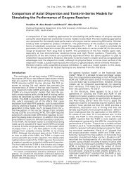
<strong>Performance</strong> <str<strong>on</strong>g>of</str<strong>on</strong>g> <strong>FCC</strong> <strong>Catalysts</strong> Energy & Fuels, Vol. 17, No. 1, 2003 63<br />
more coke, dry gas, and less gasoline than inactive<br />
matrix. 16-18 <str<strong>on</strong>g>The</str<strong>on</strong>g> effect <str<strong>on</strong>g>of</str<strong>on</strong>g> alumina additi<strong>on</strong> to <strong>FCC</strong><br />
catalyst matrix <strong>on</strong> processing different kinds <str<strong>on</strong>g>of</str<strong>on</strong>g> VGO<br />
feedstock was studied by Otterstedt et al. 17 <str<strong>on</strong>g>The</str<strong>on</strong>g>y<br />
observed that alumina additi<strong>on</strong> to <strong>the</strong> catalyst matrix<br />
had increased <strong>the</strong> c<strong>on</strong>versi<strong>on</strong> <str<strong>on</strong>g>of</str<strong>on</strong>g> <strong>the</strong> heavier feed oil but<br />
at <strong>the</strong> same time increased coke selectivity and decreased<br />
gasoline selectivity. However, alumina additi<strong>on</strong><br />
did not have a significant effect during lighter feed oil<br />
processing. Coke and gasoline selectivities were found<br />
to have similar behavior to those <str<strong>on</strong>g>of</str<strong>on</strong>g> heavier feed oil.<br />
It has been reported that <strong>the</strong> olefin/paraffin ratio<br />
decreases by increasing zeolitic c<strong>on</strong>tent and decreasing<br />
matrix activity. 19 Moreover, Scherzer 15 claimed that<br />
increasing matrix activity (by adding alumina) would<br />
increase both olefin/paraffin ratio and gasoline octane.<br />
This was attributed to lower hydrogen transfer reacti<strong>on</strong><br />
rate versus cracking reacti<strong>on</strong> rate over amorphous<br />
matrix comp<strong>on</strong>ent.<br />
Thus, it is clearly known that alumina additi<strong>on</strong> to a<br />
<strong>FCC</strong> catalyst matrix can influence <strong>the</strong> catalyst performance<br />
by increasing catalyst acidity and surface area.<br />
C<strong>on</strong>sequently, <strong>the</strong> VGO catalytic cracking might be<br />
enhanced by alumina additi<strong>on</strong> to <strong>the</strong> matrix without<br />
changing <strong>the</strong> USY-zeolite structure.<br />
In <strong>the</strong> present study, a thorough investigati<strong>on</strong> for <strong>the</strong><br />
role <str<strong>on</strong>g>of</str<strong>on</strong>g> active matrix <strong>on</strong> catalytic cracking <str<strong>on</strong>g>of</str<strong>on</strong>g> hydrotreated<br />
VGO has been c<strong>on</strong>ducted. Systematic additi<strong>on</strong><br />
<str<strong>on</strong>g>of</str<strong>on</strong>g> alumina to both matrix samples and <strong>FCC</strong> catalysts<br />
c<strong>on</strong>taining USY-zeolite has been studied. Testing both<br />
catalyst systems under standard MAT c<strong>on</strong>diti<strong>on</strong>s has<br />
been carried out. <str<strong>on</strong>g>The</str<strong>on</strong>g> activity <str<strong>on</strong>g>of</str<strong>on</strong>g> matrix with alumina<br />
and catalyst c<strong>on</strong>taining alumina is determined. Fur<strong>the</strong>rmore,<br />
<strong>the</strong> effect <str<strong>on</strong>g>of</str<strong>on</strong>g> alumina additi<strong>on</strong> <strong>on</strong> product<br />
selectivity is highlighted.<br />
2. Experimental Secti<strong>on</strong><br />
2.1. Catalyst Preparati<strong>on</strong>. USY-zeolite was mixed with<br />
kaolin clay and stabilized silica sol (SI-550) supplied by<br />
Catalyst and Chemicals Industries Co. <str<strong>on</strong>g>The</str<strong>on</strong>g> resulting slurry<br />
was heated over a sand bath with c<strong>on</strong>tinuous stirring. <str<strong>on</strong>g>The</str<strong>on</strong>g><br />
dried product was crushed and sieved to <strong>the</strong> proper particle<br />
size (520-710 µm). <str<strong>on</strong>g>The</str<strong>on</strong>g> base catalyst, <strong>the</strong> <strong>on</strong>e with inactive<br />
matrix (CAT0), c<strong>on</strong>tained 30% zeolite, 50% kaolin, and 20%<br />
silica sol binder. <str<strong>on</strong>g>The</str<strong>on</strong>g> prepared catalysts were calcined in air<br />
at 600 °C for 2 h. Finally <strong>the</strong> catalysts were treated with 100%<br />
steam at 810 °C for 6 h.<br />
<str<strong>on</strong>g>The</str<strong>on</strong>g> series <str<strong>on</strong>g>of</str<strong>on</strong>g> catalysts c<strong>on</strong>taining <strong>the</strong> active matrices were<br />
prepared in <strong>the</strong> same manner as <strong>the</strong> <strong>on</strong>e c<strong>on</strong>taining inactive<br />
matrix with <strong>the</strong> excepti<strong>on</strong> that part <str<strong>on</strong>g>of</str<strong>on</strong>g> <strong>the</strong> kaolin was replaced<br />
by boehmite. <str<strong>on</strong>g>The</str<strong>on</strong>g> amount <str<strong>on</strong>g>of</str<strong>on</strong>g> boehmite used in <strong>the</strong>se preparati<strong>on</strong>s<br />
corresp<strong>on</strong>ded to 5 wt % (CAT5), 10 wt % (CAT10), and<br />
20 wt % (CAT20). <str<strong>on</strong>g>The</str<strong>on</strong>g> three catalysts CAT5, CAT10 and<br />
CAT20 all c<strong>on</strong>tained 30 wt % USY-zeolite and 20 wt % silica<br />
sol. <str<strong>on</strong>g>The</str<strong>on</strong>g> o<strong>the</strong>r comp<strong>on</strong>ent is <strong>the</strong> kaolin as shown Table 1.<br />
<str<strong>on</strong>g>The</str<strong>on</strong>g> series <str<strong>on</strong>g>of</str<strong>on</strong>g> matrix samples are prepared as follows;<br />
inactive matrix c<strong>on</strong>tains <strong>on</strong>ly kaolin (M0). Active matrices were<br />
prepared in <strong>the</strong> same manner as <strong>the</strong> <strong>FCC</strong> catalysts with active<br />
matrix except that in <strong>the</strong>se series no zeolite is present. Part<br />
(16) Van de Gander, P.; Penslay, R. M.; Chuang, K. C.; Cormier,<br />
W. E.; Walterman, G. M.; Boldingh, E. P. Advanced Fluid Catalytic<br />
Cracking Technology; AIChE Symposium Series vol. 88, no. 291;<br />
AIChE: New York; pp 21-29.<br />
(17) Otterstedt, J. E.; Zhu, Y.; Sterte, J. Appl. Catal. 1988, 38, 143.<br />
(18) Sterte, J.; Otterstedt, J. E. Appl. Catal. 1988, 38, 131.<br />
(19) de J<strong>on</strong>g, J. I. Ketjen Catalysis. Symposium 1986, Scheveningen,<br />
<str<strong>on</strong>g>The</str<strong>on</strong>g> Ne<strong>the</strong>rlands, Paper F-2.<br />
catalyst<br />
Table 1. Catalyst Compositi<strong>on</strong> C<strong>on</strong>tent<br />
Y-zeolite<br />
(wt %)<br />
silica sol<br />
(wt %)<br />
kaolin<br />
(wt %)<br />
alumina<br />
(wt %)<br />
CAT0 30 20 50 0<br />
CAT5 30 20 45 5<br />
CAT10 30 20 40 10<br />
CAT20 30 20 30 20<br />
M0 0 0 100 0<br />
M5 0 20 75 5<br />
M10 0 20 70 10<br />
M20 0 20 60 20<br />
Table 2. Treatment and Characterizati<strong>on</strong> <str<strong>on</strong>g>of</str<strong>on</strong>g> <strong>Catalysts</strong><br />
catalyst treatment<br />
unit cell<br />
size (Å)<br />
surface<br />
area<br />
(m 2 /g)<br />
Al<br />
(wt %)<br />
acidity<br />
(mmol/g)<br />
CAT0 steaming, 810 °C 24.206 123 0 0.0190<br />
CAT5 steaming, 810 °C 24.206 177 5 0.0296<br />
CAT10 steaming, 810 °C 24.206 180 10 0.0311<br />
CAT20 steaming, 810 °C 24.206 196 20 0.0377<br />
M0 steaming, 810 °C - 22 0 0.006<br />
M5 steaming, 810°C - 25 5 0.0088<br />
M10 steaming, 810 °C - 31.7 10 0.0114<br />
M20 steaming, 810 °C - 60 20 0.0227<br />
<str<strong>on</strong>g>of</str<strong>on</strong>g> kaolin was substituted by boehmite. <str<strong>on</strong>g>The</str<strong>on</strong>g> amount <str<strong>on</strong>g>of</str<strong>on</strong>g> boehmite<br />
used in <strong>the</strong>se preparati<strong>on</strong>s corresp<strong>on</strong>ded to 5 wt % (M5), 10<br />
wt % (M10), and 20 wt % (M20) see Table 1. All matrices were<br />
calcined in air at 600 °C for 2 h. <str<strong>on</strong>g>The</str<strong>on</strong>g>n <strong>the</strong>y were treated with<br />
100% steam at 810 °C for 6 h (see Table 2).<br />
2.2. Catalyst Characterizati<strong>on</strong>. <str<strong>on</strong>g>The</str<strong>on</strong>g> unit cell size was<br />
determined by X-ray diffracti<strong>on</strong> following ASTM D-3942-80.<br />
High purity silic<strong>on</strong> powder (99.999%) was used as <strong>the</strong> calibrati<strong>on</strong><br />
standard. Surface area <str<strong>on</strong>g>of</str<strong>on</strong>g> <strong>the</strong> sample catalyst were<br />
measured by nitrogen adsorpti<strong>on</strong> at -196 °C. <str<strong>on</strong>g>The</str<strong>on</strong>g> zeolite used<br />
has 75.9 m 2 /g surface area (this surface area is for <strong>the</strong> zeolite<br />
which is steamed at 810 °C for 8 h) and negligible Na c<strong>on</strong>tent.<br />
Moreover, <strong>the</strong> unit cell size is 24.206 Å. Hence its silica/<br />
alumina ratio can be found from this unit cell size.<br />
<str<strong>on</strong>g>The</str<strong>on</strong>g> acid property <str<strong>on</strong>g>of</str<strong>on</strong>g> <strong>the</strong> catalyst was characterized by<br />
pyridine temperature programmed desorpti<strong>on</strong> (TPD). In all<br />
experiments, 50 mg <str<strong>on</strong>g>of</str<strong>on</strong>g> sample was charged in a tubular cell.<br />
Prior to obtaining TPD spectra, <strong>the</strong> sample was outgassed at<br />
400 °C for 30 min in flowing helium and <strong>the</strong>n cooled to 150<br />
°C. At that temperature, pyridine was adsorbed <strong>on</strong> <strong>the</strong> sample<br />
by injecting pulses <str<strong>on</strong>g>of</str<strong>on</strong>g> pyridine (2ul/ pulse). <str<strong>on</strong>g>The</str<strong>on</strong>g> injecti<strong>on</strong> <str<strong>on</strong>g>of</str<strong>on</strong>g><br />
pyridine was repeated until <strong>the</strong> amount <str<strong>on</strong>g>of</str<strong>on</strong>g> pyridine detected<br />
was <strong>the</strong> same for <strong>the</strong> last two injecti<strong>on</strong>s. After <strong>the</strong> adsorpti<strong>on</strong><br />
<str<strong>on</strong>g>of</str<strong>on</strong>g> pyridine was saturated, <strong>the</strong> sample was flushed at 150 °C<br />
for 1 h with helium to remove excess pyridine and <strong>the</strong>n<br />
temperature programmed at 30 °C/min to 1000 °C in flowing<br />
helium at 30 mL/min. An FID detector was used to m<strong>on</strong>itor<br />
<strong>the</strong> desorbed pyridine. <str<strong>on</strong>g>The</str<strong>on</strong>g> properties <str<strong>on</strong>g>of</str<strong>on</strong>g> <strong>the</strong> catalysts used in<br />
<strong>the</strong> present study are presented in Table 2.<br />
2.3. Catalyst Evaluati<strong>on</strong>. Catalytic experiments were<br />
carried out in a microactivity test (MAT) unit (fixed bed), which<br />
had been designed according to <strong>the</strong> ASTM D-3907 method with<br />
minor modificati<strong>on</strong>s. <str<strong>on</strong>g>The</str<strong>on</strong>g> reactor was operated at atmospheric<br />
pressure and 520 °C. For a given catalyst, <strong>the</strong> c<strong>on</strong>versi<strong>on</strong> was<br />
varied by varying <strong>the</strong> catalyst-to-oil ratio (C/O) in <strong>the</strong> range<br />
<str<strong>on</strong>g>of</str<strong>on</strong>g> 0.5-3.0. <str<strong>on</strong>g>The</str<strong>on</strong>g> C/O ratio is defined as <strong>the</strong> amount <str<strong>on</strong>g>of</str<strong>on</strong>g> catalyst<br />
divided by <strong>the</strong> total amount <str<strong>on</strong>g>of</str<strong>on</strong>g> oil fed in a given time <strong>on</strong> stream<br />
and was varied by changing <strong>the</strong> weight <str<strong>on</strong>g>of</str<strong>on</strong>g> <strong>the</strong> catalyst while<br />
<strong>the</strong> total amount <str<strong>on</strong>g>of</str<strong>on</strong>g> oil fed and <strong>the</strong> time were kept c<strong>on</strong>stant,<br />
i.e., 1g<str<strong>on</strong>g>of</str<strong>on</strong>g><strong>the</strong>oilwascharged to <strong>the</strong> reactor in 30 s (see Table<br />
3). <str<strong>on</strong>g>The</str<strong>on</strong>g>rmal effects and changes in <strong>the</strong> bed volume were<br />
minimized by diluting <strong>the</strong> catalyst with kaolin particles<br />
(having <strong>the</strong> same size as <strong>the</strong> catalyst particle), and <strong>the</strong> total<br />
weight <str<strong>on</strong>g>of</str<strong>on</strong>g> <strong>the</strong> catalyst bed was kept at 3 g. <str<strong>on</strong>g>The</str<strong>on</strong>g> distributi<strong>on</strong> <str<strong>on</strong>g>of</str<strong>on</strong>g><br />
gaseous products was analyzed by gas chromatographies. <str<strong>on</strong>g>The</str<strong>on</strong>g><br />
boiling point range <str<strong>on</strong>g>of</str<strong>on</strong>g> <strong>the</strong> liquid products was determined by