DTA Desk Call Station with Call Signal
DTA Desk Call Station with Call Signal
DTA Desk Call Station with Call Signal

You also want an ePaper? Increase the reach of your titles
YUMPU automatically turns print PDFs into web optimized ePapers that Google loves.
Data Sheet<br />
<strong>DTA</strong>-012 / 030 / 048 / 066 / 084 / 114<br />
<strong>Desk</strong> <strong>Call</strong> <strong>Station</strong> <strong>with</strong> <strong>Call</strong> <strong>Signal</strong> www.dvs-21.de<br />
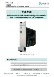
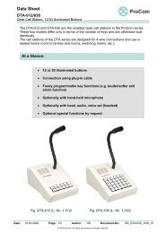
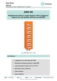
<strong>DTA</strong>-048 as call station<br />
<strong>with</strong> call signal<br />
At a Glance:<br />
<strong>DTA</strong><br />
<strong>Desk</strong> <strong>Call</strong> <strong>Station</strong> <strong>with</strong> <strong>Call</strong> <strong>Signal</strong><br />
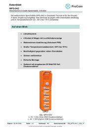
<strong>DTA</strong>-030 as malfunction alert<br />
panel (product example)<br />
Fig. 1 Fig. 2<br />
• Model as call station <strong>with</strong> call signal (standard) or purely as malfunction al<br />
panel for interior rooms (control centres and rooms, switching rooms,<br />
etc.)<br />
• Scaleable housing <strong>with</strong> 12, 30, 48, 66, 84 or 114 illuminated buttons,<br />
electronics constructed identically<br />
• Large range thanks to analogue voice transmission, control and signal<br />
data over a robust modem connection<br />
• Freely programmable key functions (e.g. PA/intercom operation <strong>with</strong><br />
acknowledge function, louder/softer, and alarm display and<br />
acknowledge function)<br />
• Connection through plug-in cable <strong>with</strong> 4 or 6-wire technology<br />
• Internal function and connection test<br />
• Optionally <strong>with</strong>out gooseneck microphone/ <strong>with</strong> hand microphone<br />
/<strong>with</strong> head, audio, voice set (headset)<br />
Date: 13.03.2009 Page: 1/6 Author: VS Document-No.: DB_<strong>DTA</strong>-12-114_1059_01<br />
© 2008 ProCom, All rights and technical changes reserved
Data Sheet<br />
<strong>DTA</strong>-012 / 030 / 048 / 066 / 084 / 114<br />
<strong>Desk</strong> <strong>Call</strong> <strong>Station</strong> <strong>with</strong> <strong>Call</strong> <strong>Signal</strong> www.dvs-21.de<br />
Mechanical Data:<br />
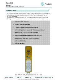
Fig. 2: Housing design 1<br />
<strong>DTA</strong>-012 / 030<br />
Fig 3: Housing design 2<br />
<strong>DTA</strong>-048 / 066<br />
Housing: Material: ABS (UL 94 HB), colour grey-white (RAL 9002)<br />
Accessories: Connecting cable 2.5 m / 15-pin D-sub connector, wall<br />
connection socket<br />
Weight: Approx. 2.5 kg (model 1) / approx. 3.5 kg (model 2)<br />
including accessories and packaging<br />
Date: 13.03.2009 Page: 2/6 Author: VS Document-No.: DB_<strong>DTA</strong>-12-114_1059_01<br />
© 2008 ProCom, All rights and technical changes reserved
Data Sheet<br />
<strong>DTA</strong>-012 / 030 / 048 / 066 / 084 / 114<br />
<strong>Desk</strong> <strong>Call</strong> <strong>Station</strong> <strong>with</strong> <strong>Call</strong> <strong>Signal</strong> www.dvs-21.de<br />
The <strong>DTA</strong> desk call station consists of the following components:<br />
o The three-part grey-white desk housing made of ABS<br />
o The aluminium mounting plate<br />
o The electrical components:<br />
- Gooseneck microphone (standard part for call station <strong>with</strong> call signal,<br />
mounted in top)<br />
- 4 W/6 W loudspeaker (mounted on aluminium plate)<br />
- Motherboard <strong>with</strong> 4 W call station amplifier (mounted in housing base)<br />
- Keypad circuit board <strong>with</strong> 30 keys (mounted on aluminium plate)<br />
- Keypad circuit board <strong>with</strong> 18/36/54 keys (mounted on aluminium plate)<br />
Included <strong>with</strong> the product are:<br />
- <strong>DTA</strong> connecting cable 2.5 m<br />
- Wall connection socket<br />
A 4NSA module is required in the system in order to connect the call stations to the<br />
DVS-21.<br />
The analogue interface module 4NSA is connected to the wall connection socket by<br />
4 or 6-wire cable and configured there according to the corresponding plug contacts.<br />
The <strong>DTA</strong> connecting cable is plugged into the 15-pin D-sub connector of the <strong>DTA</strong><br />
and configured according to the corresponding plug contacts of the wall connection<br />
socket.<br />
Order Data:<br />
Quantity of Illuminated<br />
Buttons<br />
<strong>DTA</strong>-012<br />
<strong>DTA</strong>-030<br />
<strong>DTA</strong>-048<br />
<strong>DTA</strong>-054<br />
<strong>DTA</strong>-066<br />
<strong>DTA</strong>-084<br />
<strong>DTA</strong>-114<br />
Model as <strong>Call</strong><br />
<strong>Station</strong> <strong>with</strong> <strong>Call</strong><br />
<strong>Signal</strong><br />
1.012<br />
1.030<br />
1.048<br />
-<br />
1.066<br />
1.084<br />
1.114<br />
Model as<br />
Malfunction Alert<br />
Panel<br />
-<br />
1.039<br />
1.049<br />
1.059<br />
1.069<br />
1.089<br />
1.119<br />
Date: 13.03.2009 Page: 3/6 Author: VS Document-No.: DB_<strong>DTA</strong>-12-114_1059_01<br />
© 2008 ProCom, All rights and technical changes reserved
Data Sheet<br />
<strong>DTA</strong>-012 / 030 / 048 / 066 / 084 / 114<br />
<strong>Desk</strong> <strong>Call</strong> <strong>Station</strong> <strong>with</strong> <strong>Call</strong> <strong>Signal</strong> www.dvs-21.de<br />
Technical Data:<br />
Operating Voltage: 48 V DC<br />
Power, Intercom Amplifier: 4 W<br />
Power, Booster Amplifier: 25 W (optional, external)<br />
Idle Current: 25 mA<br />
Current Consumption (Sending): 35 mA<br />
Current Consumption (Receiving)<br />
Without Booster Amplifier: Max. 200 mA<br />
Current Consumption (Receiving)<br />
With Booster Amplifier: Max. 1200 mA<br />
Nominal Impedance: 600 Ω<br />
Frequency Range: 300 - 8,000 Hz<br />
Microphone: Dynamic, directional<br />
Control Range<br />
Volume Compressor: 20 dB (speaking distance 10 - 30 cm)<br />
Sound Pressure Level: >94 dB (distance 1 m)<br />
Date: 13.03.2009 Page: 4/6 Author: VS Document-No.: DB_<strong>DTA</strong>-12-114_1059_01<br />
© 2008 ProCom, All rights and technical changes reserved
Data Sheet<br />
<strong>DTA</strong>-012 / 030 / 048 / 066 / 084 / 114<br />
<strong>Desk</strong> <strong>Call</strong> <strong>Station</strong> <strong>with</strong> <strong>Call</strong> <strong>Signal</strong> www.dvs-21.de<br />
Model as Malfunction Alert Panel:<br />
The following describes the functionality of the <strong>DTA</strong> purely as malfunction alert panel,<br />
i.e. <strong>with</strong>out PA/intercom functionality:<br />
Programming is done <strong>with</strong> the help of the ICS software.<br />
For this a block of keys (the start and end keys of the block are inputted) is<br />
established, which handles a line-on and line-off frame differently than normal line<br />
keys.<br />
If a special model of the <strong>DTA</strong> is used as malfunction alert panel then the physical start and end<br />
keys can be different than those of the standard model. If a basis housing has more than 30 keys<br />
then it is always a case of a special model. Thus the following applies<br />
(<strong>with</strong> 36-54 keys in the basis housing): Start key = 31, end key = 66 ... 84<br />
All status changes inside this block (on → off as well as off → on) are indicated<br />
optically by different blinking lights on the associated line key. Also an audio signal<br />
sounds <strong>with</strong> every status change.<br />
The blinking line keys and the audio signal are a request to the user to acknowledge<br />
the status change event by pressing the respective line key. After acknowledging, the<br />
way the line key is illuminated changes to correspond to the current status of the<br />
change.<br />
If all status changes have been acknowledged then the audio signal goes silent and<br />
is switched on again only when the next status change occurs.<br />
All line keys in a defined block work independently of one another and can be used at<br />
the same time. The audio signal sounds as soon as a status change occurs which<br />
has not yet been acknowledged.<br />
Only when all status changes have been acknowledged does the audio signal go<br />
silent.<br />
All line keys of the <strong>DTA</strong> call station can be operated simultaneously and<br />
independently of one another and also be evaluated in the DVS-21 central system<br />
simultaneously and independently of one another.<br />
Manual check and self-test:<br />
To check all optical and audio elements a separate key can be defined as lamp and<br />
signal test key.<br />
When the lamp test is activated all LEDs of the line keys are turned on to manually<br />
check the proper functioning of the display elements.<br />
The switching on or off of the display elements using the lamp test only has an effect on the<br />
regular condition of the display elements during the active lamp test function.<br />
It overrides the LED illumination only for test purposes and switches all display elements back to<br />
their original condition after the lamp test is deactivated.<br />
Date: 13.03.2009 Page: 5/6 Author: VS Document-No.: DB_<strong>DTA</strong>-12-114_1059_01<br />
© 2008 ProCom, All rights and technical changes reserved
Data Sheet<br />
<strong>DTA</strong>-012 / 030 / 048 / 066 / 084 / 114<br />
<strong>Desk</strong> <strong>Call</strong> <strong>Station</strong> <strong>with</strong> <strong>Call</strong> <strong>Signal</strong> www.dvs-21.de<br />
After the call station operating voltage is switched on or after a reset of the DVS-21<br />
central system (at the soonest 7 sec. after switching on) the call station illumination<br />
shows the availability of the key processors in use for 3 seconds.<br />
The number of illuminated LEDs shows here the respective number and the start key<br />
of the keypad block allocated to each processor.<br />
After 3 seconds the motherboard of the <strong>DTA</strong> call station carries out a preliminary<br />
initialization of all keys. When this happens the illumination of the call station keys,<br />
which indicates availability goes off, and all keys in use are queried in sequence for<br />
100 ms and tested. If this test is not completed successfully or if the start illumination<br />
does not go off then the call station is defective and should be exchanged.<br />
Application example:<br />
Original condition: illumination of all the line keys is in inactive condition<br />
(switched off).<br />
When a status change occurs (on) the LED of the respective line key begins to blink<br />
<strong>with</strong> a quick rhythm and the audio signal sounds.<br />
The change Off → On is indicated by quick blinking and an audio signal.<br />
The operator acknowledges this incoming signal by pressing the blinking line key.<br />
After that the audio signal goes off and the line key takes on the active status.<br />
The acknowledged line key is now continuously lit and the audio signal is off.<br />
When a status change occurs again (switching off of the previously switched-on line<br />
key) the LED of the line key begins to blink <strong>with</strong> a slow rhythm and the audio signal<br />
sounds again.<br />
The change Off → On is indicated by slow blinking and an audio signal.<br />
The operator acknowledges this incoming signal again by pressing the blinking line<br />
key. After that the audio signal goes off and the line key takes on the active status.<br />
The acknowledged line key is now not illuminated and the audio signal is off.<br />
All line keys in a defined block work independently of one another and can be used at<br />
the same time. The audio signal sounds as soon as a status change occurs which<br />
has not yet been acknowledged. Only when all status changes have been<br />
acknowledged does the audio signal go silent.<br />
To check all optical and audio elements a separate key can be defined as lamp and<br />
signal test key.<br />
Date: 13.03.2009 Page: 6/6 Author: VS Document-No.: DB_<strong>DTA</strong>-12-114_1059_01<br />
© 2008 ProCom, All rights and technical changes reserved