TDMA, FDMA, and CDMA
TDMA, FDMA, and CDMA
TDMA, FDMA, and CDMA

You also want an ePaper? Increase the reach of your titles
YUMPU automatically turns print PDFs into web optimized ePapers that Google loves.
<strong>TDMA</strong>, <strong>FDMA</strong>, <strong>and</strong> <strong>CDMA</strong><br />
Telecomunicazioni<br />
Undergraduate course in Electrical Engineering<br />
University of Rome La Sapienza<br />
Rome, Italy<br />
2007-2008<br />
NB --> I "case study" non sono parte delle dom<strong>and</strong>e d'esame.
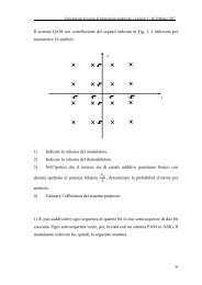
Time ime Division ivision Multiple ultiple Access ccess (<strong>TDMA</strong>)<br />
Each user is allowed to transmit only within specified time<br />
intervals (Time Slots). Different users transmit in differents Time<br />
Slots.<br />
When users transmit, they occupy the whole frequency b<strong>and</strong>width<br />
(separation among users is performed in the time domain).<br />
2
<strong>TDMA</strong> : Frame Structure<br />
<strong>TDMA</strong> requires a centralized control node, whose primary function is<br />
to transmit a periodic reference burst that defines a frame <strong>and</strong><br />
forces a measure of synchronization of all the users.<br />
The frame so-defined is divided into time slots, <strong>and</strong> each user is<br />
assigned a Time Slot in which to transmit its information.<br />
Reference<br />
Burst<br />
Frame<br />
T F<br />
T S<br />
Time Slot<br />
3
<strong>TDMA</strong> : Frame Structure<br />
User 1 User 2 User 3<br />
4
<strong>TDMA</strong> : guard times<br />
Since there are significant delays between users, each user receives<br />
the reference burst with a different phase, <strong>and</strong> its traffic burst is<br />
transmitted with a correspondingly different phase within the time slot.<br />
There is therefore a need for guard times to take account of this<br />
uncertainty.<br />
Each Time Slot is therefore longer than the period needed for the<br />
actual traffic burst, thereby avoiding the overlap of traffic burst even in<br />
the presence of these propagation delays.<br />
with guard time<br />
misalignment misalignment<br />
without guard time<br />
5
<strong>TDMA</strong> : preamble<br />
Since each traffic burst is transmitted independently with an uncertain<br />
phase relaive to the reference burst, there is the need for a preamble<br />
at the beginning of each traffic burst.<br />
The preamble allows the receiver to acquire on top of the coarse<br />
synchronization provided by the reference burst a fine estimate of<br />
timing <strong>and</strong> carrier phase.<br />
preamble information<br />
6
S<br />
Digital<br />
signal<br />
<strong>TDMA</strong>: reference transmitter scheme<br />
SLOW IN<br />
FAST OUT<br />
BUFFER<br />
Code<br />
generator<br />
<strong>TDMA</strong><br />
coder<br />
Pulse<br />
Shaper<br />
Carrier<br />
generator<br />
Mod<br />
f P<br />
S TX<br />
7
s<br />
() j () <br />
() j<br />
t = a (<br />
)<br />
k t kT<br />
Digital signal of user j<br />
Sequence of equally spaced<br />
binary antipodal symbols<br />
a k (j) : k-th binary antipodal<br />
symbol generated by user j<br />
k<br />
T : time period between symbols<br />
<strong>TDMA</strong>: a case study<br />
User<br />
j<br />
s (j) (t)<br />
1<br />
0.8<br />
0.6<br />
0.4<br />
0.2<br />
0<br />
-0.2<br />
-0.4<br />
-0.6<br />
-0.8<br />
-1<br />
0 1 2 3 4 5 6 7 8 9 10<br />
x 10 -3<br />
8
() j<br />
s () t<br />
1<br />
0.8<br />
0.6<br />
0.4<br />
0.2<br />
0<br />
-0.2<br />
-0.4<br />
-0.6<br />
-0.8<br />
-1<br />
SLOW IN<br />
FAST OUT<br />
BUFFER<br />
0 1 2 3 4 5 6 7 8 9 10<br />
x 10 -3<br />
<strong>TDMA</strong>: a case study<br />
() () t<br />
j<br />
sC Compressed signal<br />
The symbols of the original signal<br />
are organized in groups of N bps<br />
symbols. Each group is transmitted<br />
in a single Time Slot of duration T S .<br />
Time Slots are organized in frames<br />
of duration T F .<br />
9
1<br />
0.8<br />
0.6<br />
0.4<br />
0.2<br />
0<br />
-0.2<br />
-0.4<br />
-0.6<br />
-0.8<br />
-1<br />
s<br />
s<br />
j<br />
k<br />
N<br />
0 1 2 3 4 5 6 7 8 9 10<br />
x 10 -3<br />
<strong>TDMA</strong>: a case study<br />
() j () ()<br />
t = a (<br />
t kT)<br />
() j () () j<br />
t = a (<br />
t kT mT )<br />
C<br />
k<br />
bps<br />
m<br />
k=<br />
1<br />
k+<br />
mN<br />
bps<br />
T C : time interval between symbols<br />
after compression<br />
C<br />
F<br />
10
from the<br />
buffer<br />
() () t<br />
j<br />
sC Code<br />
generator<br />
<strong>TDMA</strong>: a case study<br />
<strong>TDMA</strong><br />
coder<br />
() ()<br />
s t<br />
<strong>TDMA</strong> Coded Signal<br />
j<br />
<strong>TDMA</strong><br />
The position in time of each group is<br />
modified according to the <strong>TDMA</strong> code,<br />
which is assigned to the user.<br />
In other words, the <strong>TDMA</strong> code indicates<br />
which slot inside each frame must be<br />
occupied by the user.<br />
1<br />
0.8<br />
0.6<br />
0.4<br />
0.2<br />
0<br />
-0.2<br />
-0.4<br />
-0.6<br />
-0.8<br />
-1<br />
0 1 2 3 4 5 6 7 8 9 10<br />
x 10 -3<br />
11
s<br />
s<br />
<strong>TDMA</strong>: a case study<br />
( t kT c T mT )<br />
() j () () j<br />
() j<br />
<strong>TDMA</strong><br />
() j () () j<br />
t = a (<br />
t kT mT )<br />
C<br />
t<br />
=<br />
N<br />
N<br />
m<br />
=<br />
k<br />
bps<br />
m<br />
k=<br />
1<br />
bps<br />
1<br />
a<br />
k+<br />
mN<br />
k+<br />
mN<br />
bps<br />
bps<br />
<br />
c m (j) : <strong>TDMA</strong> code assigned to<br />
user j for the m-th frame<br />
C<br />
C<br />
1<br />
0.8<br />
0.6<br />
0.4<br />
0.2<br />
0<br />
-0.2<br />
-0.4<br />
-0.6<br />
-0.8<br />
-1<br />
m<br />
F<br />
S<br />
F<br />
0 1 2 3 4 5 6 7 8 9 10<br />
x 10 -3<br />
12
from the<br />
<strong>TDMA</strong> coder<br />
1<br />
0.8<br />
0.6<br />
0.4<br />
0.2<br />
0<br />
-0.2<br />
-0.4<br />
-0.6<br />
-0.8<br />
-1<br />
() () t<br />
s j<br />
<strong>TDMA</strong><br />
0 1 2 3 4 5 6 7 8 9 10<br />
x 10 -3<br />
Pulse<br />
Shaper<br />
Carrier<br />
generator<br />
<strong>TDMA</strong>: a case study<br />
100<br />
50<br />
0<br />
-50<br />
-100<br />
Mod<br />
f P<br />
() () t<br />
j<br />
s bb<br />
0 0.002 0.004 0.006 0.008 0.01 0.012 0.014<br />
S (j) TX (t)<br />
Base-b<strong>and</strong><br />
signal<br />
100<br />
50<br />
0<br />
-50<br />
-100<br />
Transmitted signal<br />
at Radio<br />
Frequencies<br />
All users adopt the same<br />
carrier frequency f p for<br />
modulating the baseb<strong>and</strong><br />
signal<br />
0 0.002 0.004 0.006 0.008 0.01 0.012 0.014<br />
13
s<br />
<strong>TDMA</strong>: a case study<br />
( t kT c T mT )<br />
() j () () j<br />
() j<br />
<strong>TDMA</strong><br />
t<br />
=<br />
N<br />
bps<br />
m<br />
k=<br />
1<br />
a<br />
k+<br />
mN<br />
bps<br />
() j () () j<br />
t = 2P<br />
s () t<br />
TX<br />
For the sake of simplifying the notation,<br />
let us consider the simple case of BPSK<br />
(in phase carrier modulation)<br />
TX<br />
<br />
( ) ( () ) j<br />
g<br />
( t)<br />
sin 2f<br />
t +<br />
s <br />
<strong>TDMA</strong><br />
g 0 (t) : energy-normalized<br />
impulse response of the<br />
Pulse Shaper. It has<br />
unitary energy.<br />
0<br />
C<br />
m<br />
P TX : transmitted power<br />
f P : carrier frequency<br />
(j) : istantaneous phase<br />
P<br />
S<br />
F<br />
14
100<br />
50<br />
0<br />
-50<br />
-100<br />
() () t<br />
j<br />
sTX 0 0.002 0.004 0.006 0.008 0.01 0.012 0.014<br />
<strong>TDMA</strong>: a case study<br />
BEWARE!<br />
]<br />
V<br />
[<br />
e<br />
d<br />
u<br />
t<br />
i<br />
l<br />
p<br />
m<br />
A<br />
15<br />
10<br />
5<br />
0<br />
-5<br />
-10<br />
-15<br />
At risk for multi user<br />
interference!<br />
() () t<br />
s j<br />
RX<br />
0 0.002 0.004 0.006 0.008 0.01 0.012 0.014 0.016<br />
Time [s]<br />
Received signal after<br />
propagation over a<br />
two-paths channel<br />
15
Front-end filtering<br />
Demodulation<br />
Sampling<br />
Threshold detection<br />
<strong>TDMA</strong>: a case study<br />
004 0.006 0.008 0.01 0.012 0.014 0.016<br />
Time [s]<br />
1 2 3 4 5 6 7 8 9 10<br />
x 10<br />
Received<br />
waveform<br />
Received<br />
binary<br />
antipodal<br />
signal<br />
16
Frequency requency Division ivision Multiple ultiple Access ccess (<strong>FDMA</strong>)<br />
Each user transmits with no limitations in time, but using only a<br />
portion of the whole available frequency b<strong>and</strong>width.<br />
Different users are separated in the frequency domain.<br />
17
<strong>FDMA</strong> vs. <strong>TDMA</strong><br />
Frequency division is very simple: all transmitters sharing the<br />
medium have output power spectra in non-overlapping b<strong>and</strong>s.<br />
Many of the problems experienced in <strong>TDMA</strong> due to different<br />
propagation delays are eliminated in <strong>FDMA</strong>.<br />
The major disadvantage of <strong>FDMA</strong> is the relatively expensive <strong>and</strong><br />
complicated b<strong>and</strong>pass filters required.<br />
<strong>TDMA</strong> is realized primarily with much cheaper logic functions.<br />
Another disadvantage of <strong>FDMA</strong> is the rather strict linearity<br />
requirement of the medium.<br />
18
S<br />
Digital<br />
signal<br />
<strong>FDMA</strong>: reference scheme<br />
Pulse<br />
Shaper<br />
Code<br />
generator<br />
Mod<br />
Carrier<br />
generator<br />
S TX<br />
19
Generated bit stream for each user<br />
1<br />
0.5<br />
0<br />
-0.5<br />
-1<br />
0 5 10<br />
x 10 -3<br />
<strong>FDMA</strong>: a case study<br />
() j<br />
s () t<br />
() j<br />
s () bb t<br />
()<br />
s () t<br />
j<br />
Digital binary signal Base-b<strong>and</strong> signal <strong>FDMA</strong>-coded signal<br />
<strong>FDMA</strong><br />
60<br />
40<br />
20<br />
0<br />
-20<br />
-40<br />
Signal after Pulse Shaping<br />
-60<br />
0 0.005 0.01 0.015<br />
60<br />
40<br />
20<br />
0<br />
-20<br />
-40<br />
Signal after <strong>FDMA</strong> coding<br />
-60<br />
0 0.005 0.01 0.015<br />
20
s<br />
<strong>FDMA</strong>: a case study<br />
() j () <br />
() j<br />
t = a (<br />
)<br />
k t kT<br />
k<br />
() j () () j<br />
t = s () t g<br />
() t<br />
s bb<br />
0<br />
( ( ) () ) j<br />
f<br />
t +<br />
() () () () () j<br />
j<br />
j<br />
t = 2P<br />
s ( t)<br />
sin 2<br />
f + c t<br />
s <br />
<strong>FDMA</strong><br />
S TX (j) (t)<br />
TX<br />
Digital binary signal<br />
Base-b<strong>and</strong> signal<br />
<strong>FDMA</strong>-coded signal<br />
bb<br />
f : frequency spacing between adjacent users<br />
c (j) : <strong>FDMA</strong> code assigned to user j<br />
P<br />
21
Propagation<br />
Demodulation<br />
(Decoding Decoding)<br />
Sampling<br />
Threshold<br />
detection<br />
]<br />
V<br />
[<br />
e<br />
d<br />
u<br />
t<br />
i<br />
l<br />
p<br />
m<br />
A<br />
]<br />
V<br />
[<br />
e<br />
d<br />
u<br />
t<br />
i<br />
l<br />
p<br />
m<br />
A<br />
8<br />
6<br />
4<br />
2<br />
0<br />
-2<br />
-4<br />
-6<br />
40<br />
20<br />
0<br />
-20<br />
<strong>FDMA</strong>: a case study<br />
-8<br />
0 0.005 0.01<br />
Time [s]<br />
0.015 0.02<br />
Received Signal after Demodulation (Decoding)<br />
-40<br />
Transmitted<br />
-60<br />
Received<br />
0 0.002 0.004 0.006 0.008 0.01 0.012 0.014 0.016 0.018<br />
4<br />
2<br />
0<br />
-2<br />
-4<br />
-6<br />
1.5<br />
x 10 -3 Samples of the received waveform<br />
-4 -2 0 2 4 6 8 10 12 14 16<br />
1<br />
0.5<br />
0<br />
-0.5<br />
-4 -2 0 2 4 6 8 10 12 14 16<br />
Transmitted<br />
signal at RF<br />
Received<br />
base-b<strong>and</strong><br />
waveform<br />
Samples at<br />
the receiver<br />
output<br />
Received<br />
binary<br />
stream<br />
22
<strong>TDMA</strong> + <strong>FDMA</strong><br />
<strong>FDMA</strong> <strong>TDMA</strong> + <strong>FDMA</strong><br />
23
<strong>TDMA</strong> + <strong>FDMA</strong> in GSM900 st<strong>and</strong>ard<br />
24
Code ode Division ivision Multiple ultiple Access ccess (<strong>CDMA</strong>)<br />
25
<strong>CDMA</strong>: basic principles<br />
In <strong>CDMA</strong> each user is assigned a unique code sequence (spreading<br />
code), which it uses to encode its data signal.<br />
The receiver, knowing the code sequence of the user, decodes the<br />
received signal <strong>and</strong> recovers the original data.<br />
The b<strong>and</strong>width of the coded data signal is chosen to be much larger<br />
than the b<strong>and</strong>width of the original data signal, that is, the encoding<br />
process enlarges (spreads) the spectrum of the data signal.<br />
<strong>CDMA</strong> is based on spread-spectrum modulation.<br />
If multiple users transmit a spread-spectrum signal at the same time,<br />
the receiver will still be able to distinguish between users, provided<br />
that each user has a unique code that has a sufficiently low crosscorrelation<br />
with the other codes.<br />
26
<strong>CDMA</strong> schemes<br />
Direct Sequence <strong>CDMA</strong> (DS-<strong>CDMA</strong>)<br />
The original data signal is multiplied directly by the high chip rate<br />
spreading code.<br />
Frequency Hopping <strong>CDMA</strong> (FH-<strong>CDMA</strong>)<br />
The carrier frequency at which the original data signal is transmitted is<br />
rapidly changed according to the spreading code.<br />
Time Hopping <strong>CDMA</strong> (TH-<strong>CDMA</strong>)<br />
The original data signal is not transmitted continuously. Instead, the<br />
signal is transmitted in short bursts where the times of the bursts are<br />
decided by the spreading code.<br />
27
C x<br />
x(t) s(t)<br />
CODING<br />
B<strong>and</strong> of the original<br />
signal<br />
Direct Sequence Spread Spectrum<br />
frequency<br />
b<strong>and</strong> of the coded signal<br />
frequency<br />
28
Direct Sequence Spread Spectrum<br />
Original signal<br />
(b<strong>and</strong> related to the bit rate)<br />
Spreading sequence composed by<br />
chips, with chip rate >> bit rate<br />
Coded signal<br />
(b<strong>and</strong> related to the chip rate)<br />
29
Signal 1<br />
Signal 2<br />
Direct Sequence Spread Spectrum<br />
Coded signal<br />
1<br />
Coded signal<br />
2<br />
Sum of coded<br />
signals 1 <strong>and</strong> 2<br />
30
Received signal<br />
signal 1<br />
Direct Sequence Spread Spectrum<br />
code used for signal 1<br />
multiplier<br />
decoded signal<br />
31
Frequency Hopping Spread Spectrum<br />
In FH-SS, the transmitter spreads the spectrum by continuously<br />
jumping from one frequency channel to another<br />
A larger number of intervals leads to a better spreading<br />
Each user selectees the next frequency hop according to a code<br />
(FH code)<br />
32
Frequency Hopping Spread Spectrum<br />
Time-frequency occupation for a FH-SS signal<br />
Dwell time<br />
f<br />
f9<br />
f8<br />
f7<br />
f6<br />
f5<br />
f4<br />
f3<br />
f2<br />
f1<br />
f0<br />
FH code period<br />
t<br />
33
Frequency Hopping Spread Spectrum<br />
FH-SS signal robustness to a interferers at constant frequency<br />
Interference limited<br />
a un dwell time<br />
f<br />
f9<br />
f8<br />
f7<br />
f6<br />
f5<br />
f4<br />
f3<br />
f2<br />
f1<br />
f0<br />
Interferer at<br />
constant frequency<br />
t<br />
34
Frequency Hopping Spread Spectrum<br />
Coexistence of different FH-SS signals<br />
Signal 1<br />
Signal 2<br />
f<br />
f9<br />
f8<br />
f7<br />
f6<br />
f5<br />
f4<br />
f3<br />
f2<br />
f1<br />
f0<br />
If codes are well chosen (orthogonal) No interference!!<br />
t<br />
35
<strong>CDMA</strong> : the partial correlation problem<br />
Partial correlations among encoded signals arise when no attempt<br />
is made to synchronize the transmitters sharing the channel, or<br />
when propagation delays cause misalignment even when<br />
transmitters are synchronized.<br />
Partial correlations impede the receiver to totally cancel the<br />
contributions of other users even in the presence of spreading<br />
codes having low cross-correlation.<br />
In presence of partial correlations, the received signal is therefore<br />
affected by Multi User Interference.<br />
The partial correlations can be reduced by proper choice of the<br />
spreading codes, but cannot be totally eliminated.<br />
<strong>CDMA</strong> system capacity is thus tipically limited by the<br />
interference from other users, users,<br />
rather than by thermal noise.<br />
noise<br />
36
<strong>CDMA</strong> : the near-far problem<br />
If all the users transmit at the same power level, then the received<br />
power is higher for transmitters closer to the receiving antenna.<br />
Thus, transmitters that are far from the receiving antenna are at a<br />
disadvantage with respect to interference from other users.<br />
This inequity can be compensated by using power control. control<br />
Each transmitter can accept central control of its transmitted power,<br />
such that the power arriving at the common receiving antenna is the<br />
same for all transmitters.<br />
In other words, the nearby transmitters are assigned a lower<br />
transmit power level than the far away transmitters.<br />
Power control can be easily achieved in centralized access<br />
schemes (e.g. third generation cellular networks), but is a<br />
challenging issue in distributed systems.<br />
37
S<br />
Digital<br />
signal<br />
DS-<strong>CDMA</strong>: reference scheme<br />
<strong>CDMA</strong> coder<br />
(multiplier)<br />
Code<br />
generator<br />
Transmitter<br />
Pulse<br />
Shaper<br />
Carrier<br />
generator<br />
Mod<br />
f P<br />
S TX<br />
38
DS-<strong>CDMA</strong>: reference scheme<br />
Front-End<br />
filter <strong>and</strong> Multiplier Integrator<br />
the<br />
S to<br />
RX<br />
demodulator<br />
Received<br />
signal<br />
Code<br />
generator<br />
Receiver<br />
decisor<br />
39
1<br />
0.8<br />
0.6<br />
0.4<br />
0.2<br />
0<br />
-0.2<br />
-0.4<br />
-0.6<br />
-0.8<br />
Generated bit stream for each user<br />
-1<br />
0 5 10<br />
x 10 -3<br />
DS-<strong>CDMA</strong>: a case study<br />
() j<br />
s () t<br />
() j<br />
c [] k<br />
()<br />
s () t<br />
j<br />
binary data signal Codeword DS-<strong>CDMA</strong>-coded signal<br />
DS<strong>CDMA</strong><br />
1<br />
0.5<br />
0<br />
-0.5<br />
-1<br />
Assigned Codeword<br />
0 2 4 6 8<br />
Binary signal after coding for each user<br />
1<br />
0.8<br />
0.6<br />
0.4<br />
0.2<br />
0<br />
-0.2<br />
-0.4<br />
-0.6<br />
-0.8<br />
-1<br />
0 0.005 0.01<br />
40
s<br />
DS-<strong>CDMA</strong>: a case study<br />
s<br />
Digital binary signal<br />
t =<br />
j<br />
a<br />
k k t<br />
() j () <br />
() ( kT)<br />
DS-<strong>CDMA</strong>-coded signal<br />
N<br />
() j () () j () j<br />
t = a c [ m]<br />
(<br />
t mT kT)<br />
DS<strong>CDMA</strong><br />
N DS : length of the codeword<br />
T C : chip time<br />
() j () () j<br />
t = 2P<br />
s () t<br />
TX<br />
TX<br />
k k<br />
=<br />
m<br />
DS<br />
1<br />
( ) ( () ) j<br />
g<br />
( t)<br />
sin 2f<br />
t +<br />
s <br />
DS<strong>CDMA</strong><br />
() j () () j () () j () () j () j () j<br />
s RX<br />
t<br />
=<br />
s<br />
TX<br />
t<br />
h<br />
t<br />
=<br />
L<br />
<br />
l=<br />
1<br />
<br />
0<br />
l<br />
s<br />
TX<br />
Spreading Signal<br />
P<br />
( t )<br />
l<br />
C<br />
Transmitted<br />
signal<br />
Signal after<br />
propagation over a<br />
multipath channel<br />
41
V<br />
[<br />
e<br />
d<br />
u<br />
t<br />
i<br />
l<br />
p<br />
m<br />
A<br />
]<br />
V<br />
[<br />
e<br />
d<br />
u<br />
t<br />
i<br />
l<br />
p<br />
m<br />
A<br />
]<br />
V<br />
[<br />
e<br />
d<br />
u<br />
t<br />
i<br />
l<br />
p<br />
m<br />
A<br />
1<br />
0<br />
-1<br />
1<br />
0<br />
-1<br />
5<br />
0<br />
-5<br />
x 10 -4 Received Signal after Demodulation<br />
DS-<strong>CDMA</strong>: a case study<br />
0 0.001 0.002 0.003 0.004 0.005 0.006 0.007 0.008 0.009 0.01<br />
x 10 -4 Received Signal after Code Multiplication<br />
0 0.001 0.002 0.003 0.004 0.005 0.006 0.007 0.008 0.009 0.01<br />
x 10 -4 Received Signal after Integration<br />
0 0.001 0.002 0.003 0.004 0.005 0.006 0.007 0.008 0.009 0.01<br />
Received signal after<br />
Front-End filtering <strong>and</strong><br />
demodulation<br />
Signal obtained by direct<br />
multiplication of the baseb<strong>and</strong><br />
signal with the<br />
spreading signal<br />
Received sequence<br />
after integration of the<br />
above samples<br />
42