Operating Manual - SCHNIER Elektrostatik GmbH
Operating Manual - SCHNIER Elektrostatik GmbH
Operating Manual - SCHNIER Elektrostatik GmbH

You also want an ePaper? Increase the reach of your titles
YUMPU automatically turns print PDFs into web optimized ePapers that Google loves.
1<br />
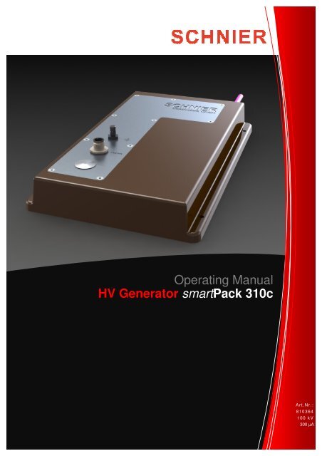
<strong>Operating</strong> <strong>Manual</strong><br />
HV Generator smartPack 310c<br />
Art.Nr.:<br />
810364<br />
100 kV<br />
300 µA
Contents<br />
1. Product and Manufacturer 3<br />
1.1. Product Identification 3<br />
1.2. Marking 3<br />
1.3. Warranty 3<br />
1.4. Manufacturer 3<br />
2. About this operating manual 4<br />
2.1. Accessibility of the manual 4<br />
2.1. Work safety icons and expressions 4<br />
3. Intended Use 5<br />
3.1. Further Requirements for the Stationary Equipment 5<br />
3.2. Particular Notes 6<br />
4. Installation 7<br />
4.1. Description 7<br />
4.2. Dimensional Drawing 9<br />
4.3. Electrical Installation / Connectors 10<br />
Grounding 10<br />
High Voltage Connector 11<br />
M12 Bus and Power Connector 11<br />
5. Normal Operation 12<br />
5.1. Safe shut down of the high voltage before access to live parts 13<br />
6. Repair and Maintenance 13<br />
7. Functional Description 14<br />
7.1. General 14<br />
7.2. Safety 14<br />
7.3. Block Diagram 15<br />
7.4. Specification 15<br />
8. Description of the CANopen Interface using PDOs 16<br />
8.1. Description of Control Word 19<br />
8.2. Description of Status Word 20<br />
8.3. Additional Parameter Settings using SDOs 22<br />
8.4. Interface Description File EDS 22<br />
8.5. Overview Control and Status Word 23<br />
8.6. Object Dictionary 24<br />
9. Declaration of Conformity 25<br />
<strong>Operating</strong> Instructions 810364_BAL_EN120302 Stand 02.03.2012 Seite 2 von 25
1. Product and Manufacturer<br />
1.1. Product Identification<br />
This <strong>Operating</strong> <strong>Manual</strong> is part of the device:<br />
Product: High Voltage Generator<br />
Type: smartPack 310c<br />
Part Number: 810364<br />
1.2. Marking<br />
1.3. Warranty<br />
Any warranty is void if the device is opened and/or modified, if parts were replaced by<br />
others than the original ones or if this operating manual is not observed.<br />
1.4. Manufacturer<br />
<strong>SCHNIER</strong> <strong>Elektrostatik</strong> <strong>GmbH</strong><br />
Bayernstr. 13<br />
72768 Reutlingen<br />
Germany<br />
Fon: +49 (0) 71 21 / 90 973 -60<br />
Fax: +49 (0) 71 21 / 90 973 -99<br />
www.schnier-elektrostatik.de<br />
mail@schnier-elektrostatik.de<br />
Headquarters: Reutlingen HBR 354 531<br />
USt.-IdNr.: DE 146 481 986<br />
General Manager: Olav Schnier<br />
<strong>Operating</strong> Instructions 810364_BAL_EN120302 Stand 02.03.2012 Seite 3 von 25
2. About this operating manual<br />
This operating <strong>Manual</strong> has to be read, understood and observed in all items by all persons<br />
who are responsible for the devices and the electrostatic plant. Only with the<br />
knowledge of this operating manual faults can be avoided and a trouble free operations<br />
be guaranteed. <strong>SCHNIER</strong> does not assume any liability for damage resulting from the<br />
non-observance of these operating instructions. Therefore it is important that the <strong>Manual</strong><br />
is known to all people involved.<br />
This operating instructions are intended for:<br />
Installation and maintenance personnel (e.g. machine setters, IT professionals,<br />
electrically qualified people) who have been trained by the manufacturer or operator<br />
using the manual and the relevant safety regulations.<br />
Operation personnel (e.g. machine setters, IT professionals, electrically qualified<br />
people) who have been trained by the manufacturer or operator using the manual and<br />
the relevant safety regulations.<br />
2.1. Accessibility of the manual<br />
This operating manual should be available and within reach to the involved operating,<br />
maintenance and service personal at all times.<br />
The operating company has to keep this manual over the whole lifetime of the installation.<br />
Since it is part of the installation this manual has to be handed over to the new owner in<br />
case of resale of the installation or the resale of parts of it.<br />
2.1.Work safety icons and expressions<br />
Icon Impact<br />
This icon indicates a warning of a potentially hazardous situation which, if not<br />
avoided, could result in death or injury.<br />
This icon indicates a warning of a potentially hazardous electrical shock situa-<br />
tion which, if not avoided, could result in death or injury.<br />
Warning of damage to equipment or malfunction<br />
Efficient Approach<br />
The expression „live parts“ or “active parts” is used in this operating manual for „parts<br />
that are at High Voltage potential during normal operation.<br />
<strong>Operating</strong> Instructions 810364_BAL_EN120302 Stand 02.03.2012 Seite 4 von 25
3. Intended Use<br />
This Product is dedicated for the use in stationary installations which comply with the<br />
safety requirements of at least one of this harmonized standards:<br />
EN 50176:2009,<br />
EN 50177:2009,<br />
EN 50223:2010 or<br />
EN 50348 :2010<br />
This high voltage generator is classified as category 3G and/or 3D equipment for use in<br />
Zone 2 and/or Zone 22 in potentially explosive atmospheres.<br />
Permitted is only the use in potentially explosive atmospheres which are caused by the<br />
spray cloud of the processed coating material itself.<br />
WARNING<br />
any other or extended use is strictly prohibited and lead to a potentially<br />
hazardous situation which could result in death or injury<br />
This device must not be used stand-alone. It has to be fully installed in stationary<br />
equipment that complies in total with the product standards mentioned above.<br />
3.1.Further Requirements for the Stationary Equipment<br />
This HV-generator must be used only in electrostatic units within a temperature<br />
range of 15 °C to 40 °C and a relative humidity between 10%<br />
and 70%.(non-condensing)<br />
This HV-generator is intended for incorporation in a given fixed<br />
installation in industrial environments. There may be difficulties to ensure<br />
electromagnetic compability (EMC) in other environments.<br />
To avoid potentially hazardous situations it is necessary to do a risk analysis<br />
of the installation in total. Particularly with regard to safety categories<br />
and/or performance levels stated in the relevant product standards this is<br />
mandatory*<br />
* Since the spray system is connected via a high voltage cable to the high voltage generator,<br />
a performance level cannot be ensured by the high voltage generator alone. For<br />
this, a second high voltage cable from the spray system returned to a redundant measurement<br />
path in the high voltage generator would be necessary.<br />
<strong>Operating</strong> Instructions 810364_BAL_EN120302 Stand 02.03.2012 Seite 5 von 25
3.2.Particular Notes<br />
The hamonized standards mentioned under „intended use“ specify safety requirements<br />
for stationary electrostatical coating equipment. For safety benefit particular sections<br />
are listed here for your information:<br />
Section<br />
5.2.1<br />
(5.3.1)<br />
5.2.3<br />
5.2.4<br />
(5.3.3)<br />
(5.3.4)<br />
[5.2.3]<br />
5.4.5<br />
(5.5.2.3)<br />
[5.3.2]<br />
5.5.<br />
[(5.4)]<br />
5.6.<br />
(5.5.2.1)<br />
[5.5]<br />
5.7.<br />
(5.5.2.2)<br />
[5.6.1]<br />
The distance between the workpieces and the parts of the<br />
spraying system under high voltage shall be large enough to<br />
prevent an electrical discharge during normal operation.<br />
After switching off the high voltage all active parts shall be<br />
discharged to a discharge energy of less than 350 mJ before<br />
these parts can be reached.<br />
If ignitable liquids are used for cleaning purposes the remaining<br />
discharge energy has to be less than 0.24 mJ before<br />
these parts can be reached.<br />
When using walls, enclosures, signs and labels made of nonconductive<br />
material the occurence of propagating brush discharges<br />
shall be prevented.<br />
Thin sheets of plastic material less than 9mm thick in contact<br />
with large areas of earthed conductors (e.g. metal) can cause<br />
brush discharges. The breakdown voltage of such sheets<br />
shall not exceed 4kV<br />
Describes all of the requirements for the high voltage supply<br />
Before any access to live parts the high voltage must be<br />
switched off and the life parts be discharged to a safe level.<br />
The electric equipment that is not part of the high voltage<br />
supply shall comply with EN 60204-1<br />
All conductive components of the installation like floors, containers<br />
etc within the spraying area except for parts under<br />
high voltage for operational reasons shall be connected to<br />
the grounding system with not more than 1 MΩ<br />
Section numbers refer to the standards EN50176/EN50177 - (EN50223) - [EN 50348].<br />
Note: This extract does not replace the fulfillment of all of the safety requirements in<br />
these standards.<br />
<strong>Operating</strong> Instructions 810364_BAL_EN120302 Stand 02.03.2012 Seite 6 von 25
4. Installation<br />
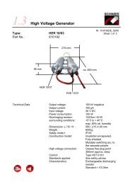
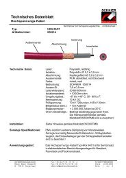
4.1. Description<br />
1 M12 5-pin-connector (24V and CAN)<br />
2 Ground connector M4 Screw or POAG (see 4.4.)<br />
3 Aluminium front panel<br />
4 Epoxy housing<br />
5 HV cable<br />
1<br />
2<br />
<strong>Operating</strong> Instructions 810364_BAL_EN120302 Stand 02.03.2012 Seite 7 von 25<br />
3<br />
4<br />
5
Abb.1<br />
Mounting<br />
This HV generator is designed to be mounted on a plate.<br />
Use hexagon socket screws M5x16mm.<br />
WARNING<br />
Excessive tightening of the screws will possibly cause<br />
cracks<br />
<strong>Operating</strong> Instructions 810364_BAL_EN120302 Stand 02.03.2012 Seite 8 von 25
4.2. Dimensional Drawing<br />
<strong>Operating</strong> Instructions 810364_BAL_EN120302 Stand 02.03.2012 Seite 9 von 25
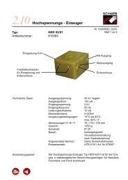
4.3. Electrical Installation / Connectors<br />
Grounding<br />
Bus and power connector<br />
With the ground connector the high voltage circuit is closed between the generator and<br />
the work piece.<br />
HV-Generator<br />
HV Ground Screw (M4)<br />
WARNING<br />
Ground wiring should be done as short as possible and at least<br />
with 4 mm 2 (AWG 11) wire.<br />
Do not place this wiring in parallel to supply or bus lines.<br />
If a POAG Connector is built in instead of a M4 Screw the<br />
following connector is needed:<br />
Designation: Winkelbuchse für<br />
Potenzialausgleich POAG<br />
Crimp connector<br />
<strong>SCHNIER</strong> Part.-No.: 260066<br />
Ground connector<br />
Spraying System Workpiece<br />
As short as possible<br />
<strong>Operating</strong> Instructions 810364_BAL_EN120302 Stand 02.03.2012 Seite 10 von 25
High Voltage Connector<br />
The 4mm HV Pin of the HV cable has to be inserted completely in<br />
the HV jack inside the generator. The cable gland has to be tightened<br />
properly<br />
ATTENTION<br />
If shielded HV cable is used the shield has to be grounded<br />
ATTENTION<br />
To avoid the appearance of ozone and oxidation it is recommended<br />
to grease the contact pin.<br />
If High voltage cable is used which contains inner conductors<br />
made of plastic the cable must not be greased.<br />
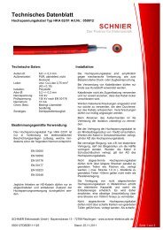
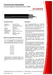
M12 Bus and Power Connector<br />
Power supply and bus interface is done in this connector<br />
Pin Description Signal<br />
1 Shield GND<br />
2 V+ 24 V DC<br />
3 V- 0 V DC / GND<br />
4 CAN_H CAN High<br />
5 Can_L CAN Low<br />
Screw Shield<br />
ATTENTION<br />
The connected cable has to be shielded<br />
Screw has to be tightened for operation.<br />
ATTENTION<br />
Connection of CAN_H and/or CAN_L to other signals than CAN<br />
bus may damage the unit. Don’t connect the CAN-Bus to 24V !<br />
A IP 54 protected female connector has to be used<br />
<strong>Operating</strong> Instructions 810364_BAL_EN120302 Stand 02.03.2012 Seite 11 von 25<br />
4<br />
5<br />
3 2<br />
1
5. Normal Operation<br />
The terms for the intended use as specified above are mandatory. Furthermore the<br />
operating instructions of the surrounding installation have to be observed.<br />
The operation of the installation has to be performed by a trained service team. The<br />
staff must be informed at reasonable intervals about accident prevention regulations<br />
and operation instructions.<br />
ATTENTION<br />
High voltage has to be switched off prior to disconnecting the 24V<br />
Power Line. Exception: emergency situations<br />
WARNING<br />
At working situations where active HV parts can be reached it is<br />
mandatory that:<br />
High Voltage is switched off !<br />
The active parts have to be discharged to less than 350 mJ<br />
If ignitable liquids are used for cleaning purposes the active<br />
parts havde to be discharged to less than 0.24 mJ<br />
24V power line is safely disconnected and secured against<br />
reconnecting.<br />
The active parts are grounded with a suitable earth rod<br />
The housing of the high voltage generator is also used for cooling.<br />
For this purpose the housing should be kept clean.<br />
Never operate a broken or opened device.<br />
During repair and maintenance of the surrounding installation the terms for the normal<br />
use of this HV generator apply. Do NOT work at installations under high tension<br />
<strong>Operating</strong> Instructions 810364_BAL_EN120302 Stand 02.03.2012 Seite 12 von 25
5.1. Safe shut down of the high voltage before access to live parts<br />
In order to ensure the safety it is mandatory to follow the steps 1-5 mentioned below<br />
before and during a release of access to live electrical components. This has also to be<br />
ensured by technical means:<br />
1. Switch off high voltage via CAN bus command<br />
2. Wait until generator sets the bit „High voltage is off safely“. This should occur after<br />
10 to 60 seconds. For safety reasons this duration should be observed over<br />
life time to recognize changes of the electical capacity of the installation.<br />
3. Switch off 24V supply (safe)<br />
4. Take measures to secure 24V supply against reconnecting<br />
5. Ground active parts with earth stick<br />
6. Repair and Maintenance<br />
The terms for the normal use as specified above apply also during repair and maintenance<br />
situations. Furthermore the operating instructions of the surrounding installation<br />
have to be observed.<br />
This HV generator does not contain any user repairable parts. It can only be repaired<br />
by the manufacturer.<br />
If the generator has to be uninstalled for repair the following order of disconnecting the<br />
Signals is recommended:<br />
1. Check if parts carrying HV during normal operation are grounded<br />
2. Remove M12 connector<br />
3. Unplug HV connector<br />
4. Remove ground<br />
WARNING<br />
If a HV generator is uninstalled avoid to touch metallic parts,<br />
that are active during operation without grounding them with an<br />
earth stick BEFORE the ground connector of the HV generator<br />
is disconnected !<br />
Observe this in particular when a generator is defect !<br />
Any warranty is void if the HV generator is opened and/or<br />
modified, if parts were replaced by others than the original<br />
ones.<br />
<strong>Operating</strong> Instructions 810364_BAL_EN120302 Stand 02.03.2012 Seite 13 von 25
7. Functional Description<br />
7.1. General<br />
The high voltage generator is built as a compact design. The control, power amplifier,<br />
the transformer and the HV multiplier are combined in one device. Supply Voltage is<br />
24 V DC. The built-in microcontroller provides a very accurate and fast control of the<br />
HV output.<br />
7.2. Safety<br />
The voltage (U) at the HV connector is measured permanently even after switching off<br />
the high voltage. With a given capacity (C) one can calculate the discharging energy<br />
(E) that remains in the spraying system and the high voltage supply system:<br />
E=1/2C* U 2<br />
E: remaining discharging energy after switch off in Joule<br />
C: total capacity of the whole HV supply system in Farad<br />
U: Voltage level in Volt<br />
Factory preset for the calculation by the HV generator is 3nF. This value can be<br />
changed via CAN bus to the actual capacity of the installation (not yet implemented).<br />
Based on the limit of 0.24mJ (EN 50176,50177,50223) for the discharge energy to be<br />
safe the hv generator sets the bit “high voltage is off safely” in the status word if E is<br />
below this limit. Otherwise the bit is reset. For 3nF and 0.24mJ the voltage limit is about<br />
400V.<br />
WARNING<br />
If a Generator has to be removed for repair –<br />
especially after the occurence of failures of selftests –<br />
Observe Section 6 of this manual.<br />
<strong>Operating</strong> Instructions 810364_BAL_EN120302 Stand 02.03.2012 Seite 14 von 25
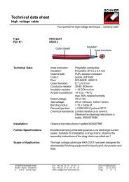
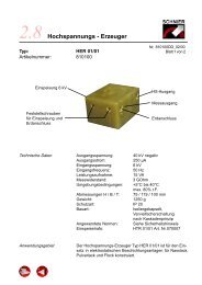
7.3. Block Diagram<br />
24 VDC<br />
CANopen<br />
Power<br />
Stagel<br />
7.4. Specification<br />
Micro<br />
Controller<br />
Transformer<br />
I-Measurement<br />
U-Measurement<br />
HV Multiplier Protection HS-<br />
Resistor Ausgang<br />
Measurement<br />
Resistor<br />
Supply Voltage 24 V DC max. 2A<br />
Output Voltage 10-100 kV negative<br />
Output Current 300uA<br />
Max. installation capacity 2 nF<br />
Environment +15°C bis 40°C max. 70% rel . humidity non condensing.<br />
Storage Temperature -20°C - +70°C<br />
Dimensions see 4.3.<br />
Weight Max 3,5 kg<br />
Protection IP 65<br />
HV Connector Anode tube with 4mm hv connector<br />
Bus Interface Based on CAN Open<br />
Operation Modes Constant U (Voltage) and Constant I (current)<br />
<strong>Operating</strong> Instructions 810364_BAL_EN120302 Stand 02.03.2012 Seite 15 von 25
8. Description of the CANopen Interface using PDOs<br />
ATTENTION:<br />
Node Guarding has to be activated. This is needed to<br />
recognize a communication loss between the HV unit<br />
and the master control unit to switch off HV !<br />
Node Guarding has to be activated using the<br />
CANopen objects 0x100C and 0x100D.<br />
1. This high voltage generator is controlled via the CAN interface, which uses a protocol<br />
based on CAN Open with default baud rate 250 kbit/s and default node-ID 02. The<br />
baud rates 50 kbits/s and 125 kbit/s are also available. The baud rate and the node-<br />
ID can be set by SDO. But the new settings will take effect only after a reset. After<br />
power on, a boot up message will be sent over the CAN interface when the high voltage<br />
generator is ready to operate.<br />
The high voltage generator is controlled by the receive-PDO „RXPDO1“ with the<br />
COB-ID „0x200+Node-ID“. The state of the high voltage generator is saved in the<br />
Send-PDO „TXPDO1“ with the COB-ID „0x180+NODE-ID“ and can be requested by<br />
SYN-Objekt.<br />
The content of the RXPDO1 consists of three objects from the object dictionary. The<br />
three objects are arranged fixed. (See figure 8.1.)<br />
Figure 8.1 The content of RXPDO1<br />
The content of the TXPDO1 consists of three objects defined in the object dictionary.<br />
The three objects are also arranged fixed. (See figure 8.2.)<br />
Figure 8.2 The content of TXPDO1<br />
2. If the high voltage generator is not in the state of failure, it can be switched on for<br />
example 10 kV in U-mode by RXPDO1. (See figure 8.3.) The set value of voltage<br />
must be higher than 10 kV, otherwise the high voltage will not be generated. In Umode<br />
a constant output voltage (U-set) is wanted, while the value of I-set is used to<br />
limit the voltage. The set value of current „I set“ is in this example given by 100 uA. If<br />
the output voltage reaches 10 kV and the output current lower than 100 uA, the out-<br />
<strong>Operating</strong> Instructions 810364_BAL_EN120302 Stand 02.03.2012 Seite 16 von 25
put voltage will be hold constantly. If e.g. the output current is over 100 uA before the<br />
output voltage reaches 10 kV, the output voltage will be limited in the actual level.<br />
(The high voltage generator behaves like in I-mode). To reach 10 kV in this case the<br />
current could be set by a higher value.<br />
Figure 8.3 RXPDO1 for 10 kV and 100 uA in U-mode<br />
Figure 8.4 RXPDO1 for 20 kV and 100 uA in I-mode<br />
In I-mode a constant output current (I-set) is wanted, while the value of U-set is used<br />
to limit the current. If the high voltage generator is switched on e.g. for 100 uA und 20<br />
kV in I-mode, the output current will rise to 100 uA and hold constantly, as long as the<br />
output voltage is lower than 20 kV (See figure 8.4.). If the output voltage reaches 20<br />
kV, the output current will be limited or reduced. (The high voltage generator behaves<br />
like in U-mode.)<br />
3. If the high voltage generator detects a failure during the operation, the high voltage will<br />
be switched off and a corresponding bit in the statusword will be set. The bit „Centralized<br />
failure“ will be set too, if any failure appears. The high voltage generator enters<br />
the state of failure. The states of the high voltage generator can be determined from<br />
the TXPDO1 by SYN-Object. Figure 8.5 shows the TXPDO1, as the high voltage is<br />
switched off e.g. due to exceeding of Imax in U-mode.<br />
Figure 8.5 TXPDO1 for Imax switch off in U-mode<br />
The output voltage and current will fall back to zero in ideal case. The falling speed is<br />
dependent on capacitance of the plant.<br />
4. The high voltage generator can come out of the state of failure, only if the failure is<br />
quitted and the high voltage is switched off. After that the high voltage can be<br />
switched on again. The failure should be quitted by RXPDO1 e.g. showed in figure<br />
8.6.<br />
<strong>Operating</strong> Instructions 810364_BAL_EN120302 Stand 02.03.2012 Seite 17 von 25
Figure 8.6 RXPDO1 for quitting failure.<br />
If the failure is quitted and the high voltage is switched off and the output voltage is<br />
lower than the safety level, the bit „Device is off safely“ will be set as showed in figure<br />
8.7.<br />
Figure 8.7 TXPDO1 shows the state of safety in I-mode<br />
If the high voltage is switched off, but the output voltage is higher than the safety<br />
level, the TXPDO1 could show like figure 8.8 (output voltage is 10 kV). That means,<br />
the high voltage generator is unsafe although the high voltage is already switched off.<br />
Figure 8.8 TXPDO1 shows unsafe status<br />
<strong>Operating</strong> Instructions 810364_BAL_EN120302 Stand 02.03.2012 Seite 18 von 25
8.1.Description of Control Word<br />
Byte Bit Statusbit Description<br />
0 0 Highvoltage on 1: turn on the Highvoltage<br />
0: turn off the Highvoltage<br />
1 Reset Fault 1: acknowledge failure<br />
0: no action<br />
2 Reserve<br />
3 Reserve<br />
4 Reserve<br />
5 Reserve<br />
6 Reserve<br />
7 Reserve<br />
1 0 Operation Mode 1: constant U mode:<br />
Output Voltage is regulated to the value<br />
defined in “Voltage set value”. Current is<br />
limited to the value defined in “Current set<br />
value”<br />
0: constant I mode:<br />
Output is regulated to the value defined in<br />
“Current set value”.Voltage is limited hereby<br />
to the value defined in “Voltage set value”.<br />
1 Reserve<br />
2 Reserve<br />
3 Reserve<br />
4 Reserve<br />
5 Reserve<br />
6 Reserve<br />
7 Reserve<br />
2 0 Reserve<br />
1 Reserve<br />
2 Reserve<br />
3 Reserve<br />
4 Reserve<br />
5 Reserve<br />
6 Reserve<br />
7 Reserve<br />
3 0 Reserve<br />
1 Reserve<br />
2 Reserve<br />
3 Reserve<br />
4 Reserve<br />
5 Reserve<br />
6 Reserve<br />
7 Reserve<br />
<strong>Operating</strong> Instructions 810364_BAL_EN120302 Stand 02.03.2012 Seite 19 von 25
8.2. Description of Status Word<br />
Byte Bit Statusbit Description<br />
0 0 Highvoltage is on 1: If the bit „Highvoltage on“<br />
in controlword is set and the<br />
voltage set value is higher<br />
than 10 kV.<br />
0: If the bit „Highvoltage on“<br />
in controlword is cleared<br />
and the internal regulator<br />
output is zero<br />
1 Centralized Fault 1: If any failure appears.<br />
0: No failure.<br />
2 Centralized Warning 1: If any warning appears.<br />
0: No warning<br />
3 High Voltage is off<br />
safely<br />
4 Reserve<br />
5 Reserve<br />
6 Reserve<br />
7 Reserve<br />
1 0 Operation Mode 1: U-mode.<br />
0: I-mode.<br />
1 Reserve<br />
2 Reserve<br />
3 Reserve<br />
4 Reserve<br />
5 Reserve<br />
6 Reserve<br />
7 Reserve<br />
2 0 Reserve<br />
1 Umax warning in I-<br />
Mode<br />
2 Umin switchoff in I-<br />
Mode<br />
1: If the highvoltage is<br />
switched off and the output<br />
voltage is lower than 300 V<br />
and no failure exists.<br />
0: If the highvoltage is<br />
switched on or the output<br />
voltage is higher than 400 V<br />
or any failure exists.<br />
1: If the output voltage in Imode<br />
is higher than the<br />
threshold value in object -<br />
dictionary.<br />
0: If this warning does not<br />
exist or is quitted.<br />
1: If the output voltage in Imode<br />
is lower than the<br />
threshold value in object -<br />
dictionary.<br />
0: If this failure does not<br />
exist or is quitted.<br />
If high voltage has<br />
been switched off by<br />
a fault (i.e. Imax,<br />
Umin) the fault has<br />
to be acknowledged<br />
before this bit will<br />
return to zero.<br />
See 7.2<br />
<strong>Operating</strong> Instructions 810364_BAL_EN120302 Stand 02.03.2012 Seite 20 von 25
3 Imax switchoff in Umode<br />
1: If the output current in Umode<br />
is higher than the<br />
threshold value in object -<br />
dictionary.<br />
0: If this failure does not<br />
exist or is quitted.<br />
4 Sparkover switchoff 1: If a sparkover happens.<br />
0: If this failure does not<br />
exist or is quitted.<br />
5 Reserve<br />
6 Reserve<br />
7 Node Guarding Failure<br />
1: If Nodeguarding signal is<br />
broken.<br />
0: If this failure does not<br />
exist or is quitted.<br />
3 0 Invalid Parameter 1: If any Parameter in the<br />
Object dictionary is set by<br />
an invalid value.<br />
0: If this failure does not<br />
exist or is quitted.<br />
1 U Measurement<br />
Failure<br />
2 I Measurement<br />
Failure<br />
3 Internal Power<br />
Failure<br />
4 Reserve<br />
5 Reserve<br />
6 Reserve<br />
7 Reserve<br />
1: If the voltage measurement<br />
circuit is defect.<br />
0: If this failure does not<br />
exist or is quitted.<br />
1: If the current measurement<br />
circuit is defect.<br />
0: If this failure does not<br />
exist or is quitted.<br />
1: If intern power controlling<br />
does not funktion.<br />
0: If this failure does not<br />
exist or is quitted.<br />
Check why CAN<br />
master does not<br />
send Nodeguard<br />
periodically as defined<br />
in the object<br />
0x100C<br />
Check value range<br />
of parameters sent<br />
to the HV controller<br />
Has to be checked<br />
by manufacturer if<br />
failure persists<br />
Has to be checked<br />
by manufacturer if<br />
failure persists<br />
Has to be checked<br />
by manufacturer if<br />
failure persists<br />
<strong>Operating</strong> Instructions 810364_BAL_EN120302 Stand 02.03.2012 Seite 21 von 25
8.3. Additional Parameter Settings using SDOs<br />
The following parameters are set using SDOs:<br />
Threshold of Umin-switchoff<br />
HV generator is switched off if, during<br />
constant-I-mode, output voltage drops<br />
below this value<br />
Threshold of Umax-warning During constant-I-mode the output<br />
voltage is limited to this value. A warning<br />
wil be issued if Umax is reached.<br />
Threshold of Imax-switchoff HV generator is switched off if, during<br />
constant-U-mode, output current reaches<br />
this value<br />
Sensitivity of sparkover detection This value defines the sensitivity of spark<br />
detection. Do not change!<br />
Voltage run up ramp Output voltage ramp up speed after HV<br />
is switched on<br />
8.4. Interface Description File EDS<br />
EDS files are simple text files used by network configuration tools to help you identify<br />
products and easily commission them on a network.<br />
<strong>SCHNIER</strong> provides a eds-File with all parameter and format information of the HV generator.<br />
<strong>Operating</strong> Instructions 810364_BAL_EN120302 Stand 02.03.2012 Seite 22 von 25
8.5. Overview Control and Status Word<br />
<strong>Operating</strong> Instructions 810364_BAL_EN120302 Stand 02.03.2012 Seite 23 von 25
8.6. Object Dictionary<br />
<strong>Operating</strong> Instructions 810364_BAL_EN120302 Stand 02.03.2012 Seite 24 von 25
9. Declaration of Conformity<br />
Hersteller:<br />
<strong>SCHNIER</strong> <strong>Elektrostatik</strong> <strong>GmbH</strong><br />
Bayernstrasse 13<br />
D-72768 Reutlingen<br />
Product: High Voltage Generator<br />
Type / <strong>SCHNIER</strong> Art.-Nr.: smartPACK310c / 810364<br />
Marking: II 3G/D T6 X<br />
We declare that the product named above is in conformity with the following EU directives:<br />
Applied harmonized standards:<br />
Directive 94/9/EG (ATEX)<br />
Directive 2006/42/EG (Machinery)<br />
Directive 2004/108/EG (EMC)<br />
The Directive 2006/95/EG (Low Voltage) is observed<br />
regarding their safety objectives (s. Appendix I Nr 1.5.1<br />
Directive 2006/42/EG)<br />
EN 50176:2009 Stationary electrostatic application equipment for ignitable liquid coating material - Safety requirements<br />
EN 50177:2009 Stationary electrostatic application equipment for ignitable coating powders - Safety requirements<br />
EN 50223:2010 Stationary electrostatic application equipment for ignitable flock material - Safety requirements<br />
EN 50348:2010 Stationary electrostatic application equipment for non-ignitable liquid coating material - Safety<br />
requirements<br />
EN ISO 12100-1:2003/A1:2009 Safety of machinery - General principles for design -<br />
Part 1: Basic terminology, methodology (ISO 12100-1:2003) + Amendment 1<br />
EN ISO 12100-2:2003/A1:2009 Safety of machinery - General principles for design –<br />
Part 2: Technical principles - (ISO 12100-2:2003)+ Amendment 1<br />
EN 60204-1:2006/A1:2009 Safety of machinery - Electrical equipment of machines -<br />
Part 1: General requirements (IEC 60204-1:2005, modified + Amendment 1<br />
EN 61000-6-2:2005 Electromagnetic compatibility (EMC) - Part 6-2: Generic standards - Immunity for industrial<br />
environments<br />
EN 61000-6-4:2007 Electromagnetic compatibility (EMC) – Part 6-4: Generic standards - Emission standard<br />
for industrial environments<br />
Rommelsbach 20.05.2011<br />
Olav Schnier (Geschäftsführer)<br />
<strong>Operating</strong> Instructions 810364_BAL_EN120302 Stand 02.03.2012 Seite 25 von 25