PCA9517 Level translating I2C-bus repeater - NXP Semiconductors
PCA9517 Level translating I2C-bus repeater - NXP Semiconductors
PCA9517 Level translating I2C-bus repeater - NXP Semiconductors

Create successful ePaper yourself
Turn your PDF publications into a flip-book with our unique Google optimized e-Paper software.
1. General description<br />
2. Features<br />
<strong>PCA9517</strong><br />
<strong>Level</strong> <strong>translating</strong> I 2 C-<strong>bus</strong> <strong>repeater</strong><br />
Rev. 03 — 30 January 2007 Product data sheet<br />
The <strong>PCA9517</strong> is a CMOS integrated circuit that provides level shifting between low<br />
voltage (down to 0.9 V) and higher voltage (2.7 V to 5.5 V) I 2 C-<strong>bus</strong> or SMBus applications.<br />
While retaining all the operating modes and features of the I 2 C-<strong>bus</strong> system during the<br />
level shifts, it also permits extension of the I 2 C-<strong>bus</strong> by providing bidirectional buffering for<br />
both the data (SDA) and the clock (SCL) lines, thus enabling two <strong>bus</strong>es of 400 pF. Using<br />
the <strong>PCA9517</strong> enables the system designer to isolate two halves of a <strong>bus</strong> for both voltage<br />
and capacitance. The SDA and SCL pins are over voltage tolerant and are<br />
high-impedance when the <strong>PCA9517</strong> is unpowered.<br />
The 2.7 V to 5.5 V <strong>bus</strong> B-side drivers behave much like the drivers on the PCA9515A<br />
device, while the adjustable voltage <strong>bus</strong> A-side drivers drive more current and eliminate<br />
the static offset voltage. This results in a LOW on the B-side <strong>translating</strong> into a nearly 0 V<br />
LOW on the A-side which accommodates smaller voltage swings of lower voltage logic.<br />
The static offset design of the B-side <strong>PCA9517</strong> I/O drivers prevent them from being<br />
connected to another device that has rise time accelerator including the PCA9510,<br />
PCA9511, PCA9512, PCA9513, PCA9514, PCA9515A, PCA9516A, <strong>PCA9517</strong> (B-side),<br />
or PCA9518. The A-side of two or more <strong>PCA9517</strong>s can be connected together, however,<br />
to allow a star topography with the A-side on the common <strong>bus</strong>, and the A-side can be<br />
connected directly to any other buffer with static or dynamic offset voltage. Multiple<br />
<strong>PCA9517</strong>s can be connected in series, A-side to B-side, with no build-up in offset voltage<br />
with only time of flight delays to consider.<br />
The <strong>PCA9517</strong> drivers are not enabled unless VCCA is above 0.8 V and VCC is above 2.5 V.<br />
The EN pin can also be used to turn the drivers on and off under system control. Caution<br />
should be observed to only change the state of the enable pin when the <strong>bus</strong> is idle.<br />
The output pull-down on the B-side internal buffer LOW is set for approximately 0.5 V,<br />
while the input threshold of the internal buffer is set about 70 mV lower (0.43 V). When the<br />
B-side I/O is driven LOW internally, the LOW is not recognized as a LOW by the input.<br />
This prevents a lock-up condition from occurring. The output pull-down on the A-side<br />
drives a hard LOW and the input level is set at 0.3VCCA to accommodate the need for a<br />
lower LOW level in systems where the low voltage side supply voltage is as low as 0.9 V.<br />
■ 2 channel, bidirectional buffer isolates capacitance and allows 400 pF on either side of<br />
the device<br />
■ Voltage level translation from 0.9 V to 5.5 V and from 2.7 V to 5.5 V<br />
■ Footprint and functional replacement for PCA9515/15A<br />
■ I 2 C-<strong>bus</strong> and SMBus compatible
<strong>NXP</strong> <strong>Semiconductors</strong> <strong>PCA9517</strong><br />
3. Ordering information<br />
[1] Also known as MSOP8<br />
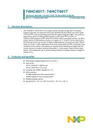
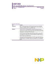
4. Functional diagram<br />
<strong>Level</strong> <strong>translating</strong> I 2 C-<strong>bus</strong> <strong>repeater</strong><br />
■ Active HIGH <strong>repeater</strong> enable input<br />
■ Open-drain input/outputs<br />
■ Lock-up free operation<br />
■ Supports arbitration and clock stretching across the <strong>repeater</strong><br />
■ Accommodates Standard mode and Fast mode I 2 C-<strong>bus</strong> devices and multiple masters<br />
■ Powered-off high-impedance I 2 C-<strong>bus</strong> pins<br />
■ A-side operating supply voltage range of 0.9 V to 5.5 V<br />
■ B-side operating supply voltage range of 2.7 V to 5.5 V<br />
■ 5 V tolerant I 2 C-<strong>bus</strong> and enable pins<br />
■ 0 Hz to 400 kHz clock frequency (the maximum system operating frequency may be<br />
less than 400 kHz because of the delays added by the <strong>repeater</strong>).<br />
■ ESD protection exceeds 2000 V HBM per JESD22-A114, 150 V MM per<br />
JESD22-A115, and 1000 V CDM per JESD22-C101<br />
■ Latch-up testing is done to JEDEC Standard JESD78 which exceeds 100 mA<br />
■ Packages offered: SO8 and TSSOP8<br />
Table 1. Ordering information<br />
Tamb = −40 °C to +85 °C<br />
Type number Topside Package<br />
mark<br />
Name Description Version<br />
<strong>PCA9517</strong>D <strong>PCA9517</strong> SO8 plastic small outline package; 8 leads; body width 3.9 mm SOT96-1<br />
<strong>PCA9517</strong>DP 9517 TSSOP8 [1] plastic thin shrink small outline package; 8 leads; body width 3 mm SOT505-1<br />
SDAA<br />
SCLA<br />
EN<br />
<strong>PCA9517</strong><br />
Fig 1. Functional diagram of <strong>PCA9517</strong><br />
002aac200<br />
<strong>PCA9517</strong>_3 © <strong>NXP</strong> B.V. 2007. All rights reserved.<br />
Product data sheet Rev. 03 — 30 January 2007 2 of 19<br />
VCCA<br />
VCCB<br />
pull-up<br />
resistor<br />
GND<br />
VCCB<br />
SDAB<br />
SCLB
<strong>NXP</strong> <strong>Semiconductors</strong> <strong>PCA9517</strong><br />
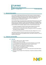
5. Pinning information<br />
5.1 Pinning<br />
VCCA<br />
5.2 Pin description<br />
6. Functional description<br />
1<br />
VCCB<br />
SCLA 2<br />
<strong>PCA9517</strong>D<br />
7 SCLB<br />
SDAA 3<br />
6 SDAB<br />
GND 4<br />
5 EN<br />
002aac198<br />
Refer to Figure 1 “Functional diagram of <strong>PCA9517</strong>”.<br />
8<br />
<strong>Level</strong> <strong>translating</strong> I 2 C-<strong>bus</strong> <strong>repeater</strong><br />
VCCA 1<br />
8 VCCB<br />
SCLA<br />
SDAA<br />
2<br />
3<br />
<strong>PCA9517</strong>DP<br />
7<br />
6<br />
SCLB<br />
SDAB<br />
GND 4<br />
5 EN<br />
002aac199<br />
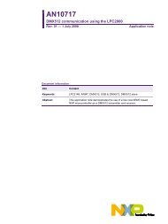
Fig 2. Pin configuration for SO8 Fig 3. Pin configuration for TSSOP8<br />
(MSOP8)<br />
Table 2. Pin description<br />
Symbol Pin Description<br />
VCCA 1 A-side supply voltage (0.9 V to 5.5 V)<br />
SCLA 2 serial clock A-side <strong>bus</strong><br />
SDAA 3 serial data A-side <strong>bus</strong><br />
GND 4 supply ground (0 V)<br />
EN 5 active HIGH <strong>repeater</strong> enable input<br />
SDAB 6 serial data B-side <strong>bus</strong><br />
SCLB 7 serial clock B-side <strong>bus</strong><br />
VCCB 8 B-side supply voltage (2.7 V to 5.5 V)<br />
The <strong>PCA9517</strong> enables I 2 C-<strong>bus</strong> or SMBus translation down to VCCA as low as 0.9 V<br />
without degradation of system performance. The <strong>PCA9517</strong> contains two bidirectional<br />
open-drain buffers specifically designed to support up-translation/down-translation<br />
between the low voltage (as low as 0.9 V) and a 3.3 V or 5 V I 2 C-<strong>bus</strong> or SMBus. All inputs<br />
and I/Os are overvoltage tolerant to 5.5 V even when the device is unpowered (VCCB<br />
and/or VCCA = 0 V). The <strong>PCA9517</strong> includes a power-up circuit that keeps the output<br />
drivers turned off until VCCB is above 2.5 V and the VCCA is above 0.8 V. VCCB and VCCA<br />
can be applied in any sequence at power-up. After power-up and with the enable (EN)<br />
HIGH, a LOW level on the A-side (below 0.3VCCA) turns the corresponding B-side driver<br />
(either SDA or SCL) on and drives the B-side down to about 0.5 V. When the A-side rises<br />
above 0.3VCCA the B-side pull-down driver is turned off and the external pull-up resistor<br />
pulls the pin HIGH. When the B-side falls first and goes below 0.3VCCB the A-side driver is<br />
turned on and the A-side pulls down to 0 V. The B-side pull-down is not enabled unless<br />
the B-side voltage goes below 0.4 V. If the B-side low voltage does not go below 0.5 V, the<br />
A-side driver will turn off when the B-side voltage is above 0.7VCCB. If the B-side low<br />
voltage goes below 0.4 V, the B-side pull-down driver is enabled and the B-side will only<br />
<strong>PCA9517</strong>_3 © <strong>NXP</strong> B.V. 2007. All rights reserved.<br />
Product data sheet Rev. 03 — 30 January 2007 3 of 19
<strong>NXP</strong> <strong>Semiconductors</strong> <strong>PCA9517</strong><br />
<strong>Level</strong> <strong>translating</strong> I 2 C-<strong>bus</strong> <strong>repeater</strong><br />
be able to rise to 0.5 V until the A-side rises above 0.3VCCA, then the B-side will continue<br />
to rise being pulled up by the external pull-up resistor. The VCCA is only used to provide<br />
the 0.3VCCA reference to the A-side input comparators and for the power good detect<br />
circuit. The <strong>PCA9517</strong> logic and all I/Os are powered by the VCCB pin.<br />
6.1 Enable<br />
The EN pin is active HIGH with an internal pull-up to VCCB and allows the user to select<br />
when the <strong>repeater</strong> is active. This can be used to isolate a badly behaved slave on<br />
power-up until after the system power-up reset. It should never change state during an<br />
I 2 C-<strong>bus</strong> operation because disabling during a <strong>bus</strong> operation will hang the <strong>bus</strong> and<br />
enabling part way through a <strong>bus</strong> cycle could confuse the I 2 C-<strong>bus</strong> parts being enabled.<br />
The enable pin should only change state when the global <strong>bus</strong> and the <strong>repeater</strong> port are in<br />
an idle state to prevent system failures.<br />
6.2 I 2 C-<strong>bus</strong> systems<br />
As with the standard I 2 C-<strong>bus</strong> system, pull-up resistors are required to provide the logic<br />
HIGH levels on the buffered <strong>bus</strong> (standard open-collector configuration of the I 2 C-<strong>bus</strong>).<br />
The size of these pull-up resistors depends on the system, but each side of the <strong>repeater</strong><br />
must have a pull-up resistor. This part designed to work with Standard mode and Fast<br />
mode I 2 C-<strong>bus</strong> devices in addition to SMBus devices. Standard mode I 2 C-<strong>bus</strong> devices only<br />
specify 3 mA output drive; this limits the termination current to 3 mA in a generic I 2 C-<strong>bus</strong><br />
system where Standard mode devices and multiple masters are possible. Under certain<br />
conditions higher termination currents can be used.<br />
Please see Application Note AN255, I 2 C/SMBus Repeaters, Hubs and Expanders for<br />
additional information on sizing resistors and precautions when using more than one<br />
<strong>PCA9517</strong> in a system or using the <strong>PCA9517</strong> in conjunction with other <strong>bus</strong> buffers.<br />
<strong>PCA9517</strong>_3 © <strong>NXP</strong> B.V. 2007. All rights reserved.<br />
Product data sheet Rev. 03 — 30 January 2007 4 of 19
<strong>NXP</strong> <strong>Semiconductors</strong> <strong>PCA9517</strong><br />
7. Application design-in information<br />
<strong>Level</strong> <strong>translating</strong> I 2 C-<strong>bus</strong> <strong>repeater</strong><br />
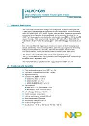
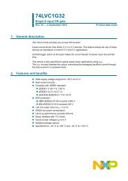
A typical application is shown in Figure 4. In this example, the system master is running<br />
on a 3.3 V I 2 C-<strong>bus</strong> while the slave is connected to a 1.2 V <strong>bus</strong>. Both <strong>bus</strong>es run at 400 kHz.<br />
Master devices can be placed on either <strong>bus</strong>.<br />
SDA<br />
SCL<br />
BUS<br />
MASTER<br />
400 kHz<br />
Fig 4. Typical application<br />
3.3 V<br />
10 kΩ 10 kΩ<br />
002aac201<br />
The <strong>PCA9517</strong> is 5 V tolerant, so it does not require any additional circuitry to translate<br />
between 0.9 V to 5.5 V <strong>bus</strong> voltages and 2.7 V to 5.5 V <strong>bus</strong> voltages.<br />
When the A-side of the <strong>PCA9517</strong> is pulled LOW by a driver on the I 2 C-<strong>bus</strong>, a comparator<br />
detects the falling edge when it goes below 0.3VCCA and causes the internal driver on the<br />
B-side to turn on, causing the B-side to pull down to about 0.5 V. When the B-side of the<br />
<strong>PCA9517</strong> falls, first a CMOS hysteresis type input detects the falling edge and causes the<br />
internal driver on the A-side to turn on and pull the A-side pin down to ground. In order to<br />
illustrate what would be seen in a typical application, refer to Figure 8 and Figure 9. If the<br />
<strong>bus</strong> master in Figure 4 were to write to the slave through the <strong>PCA9517</strong>, waveforms shown<br />
in Figure 8 would be observed on the A <strong>bus</strong>. This looks like a normal I 2 C-<strong>bus</strong> transmission<br />
except that the HIGH level may be as low as 0.9 V, and the turn on and turn off of the<br />
acknowledge signals are slightly delayed.<br />
On the B <strong>bus</strong> side of the <strong>PCA9517</strong>, the clock and data lines would have a positive offset<br />
from ground equal to the VOL of the <strong>PCA9517</strong>. After the 8th clock pulse, the data line will<br />
be pulled to the VOL of the slave device which is very close to ground in this example. At<br />
the end of the acknowledge, the level rises only to the LOW level set by the driver in the<br />
<strong>PCA9517</strong> for a short delay while the A <strong>bus</strong> side rises above 0.3VCCA then it continues<br />
HIGH. It is important to note that any arbitration or clock stretching events require that the<br />
LOW level on the B <strong>bus</strong> side at the input of the <strong>PCA9517</strong> (VIL) be at or below 0.4 V to be<br />
recognized by the <strong>PCA9517</strong> and then transmitted to the A <strong>bus</strong> side.<br />
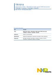
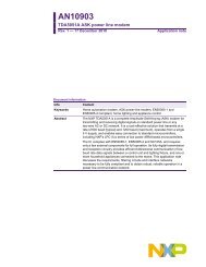
Multiple <strong>PCA9517</strong> A-sides can be connected in a star configuration (Figure 5), allowing all<br />
nodes to communicate with each other.<br />
Multiple <strong>PCA9517</strong>s can be connected in series (Figure 6) as long as the A-side is<br />
connected to the B-side. I 2 C-<strong>bus</strong> slave devices can be connected to any of the <strong>bus</strong><br />
segments. The number of devices that can be connected in series is limited by <strong>repeater</strong><br />
delay/time-of-flight considerations on the maximum <strong>bus</strong> speed requirements.<br />
<strong>PCA9517</strong>_3 © <strong>NXP</strong> B.V. 2007. All rights reserved.<br />
Product data sheet Rev. 03 — 30 January 2007 5 of 19<br />
VCCB<br />
VCCA<br />
SDAB SDAA<br />
SCLB SCLA<br />
EN<br />
<strong>PCA9517</strong><br />
1.2 V<br />
10 kΩ 10 kΩ<br />
<strong>bus</strong> B <strong>bus</strong> A<br />
SDA<br />
SCL<br />
SLAVE<br />
400 kHz
<strong>NXP</strong> <strong>Semiconductors</strong> <strong>PCA9517</strong><br />
SDA<br />
SCL<br />
10 kΩ 10 kΩ<br />
SDA<br />
SCL<br />
VCCA<br />
10 kΩ 10 kΩ<br />
Fig 5. Typical star application<br />
SDAA SDAB<br />
SCLA SCLB<br />
Fig 6. Typical series application<br />
<strong>Level</strong> <strong>translating</strong> I 2 C-<strong>bus</strong> <strong>repeater</strong><br />
<strong>PCA9517</strong>_3 © <strong>NXP</strong> B.V. 2007. All rights reserved.<br />
Product data sheet Rev. 03 — 30 January 2007 6 of 19<br />
VCCA<br />
VCCB<br />
SDAA SDAB<br />
SCLA SCLB<br />
VCCB<br />
10 kΩ 10 kΩ<br />
SDA<br />
SCL<br />
BUS<br />
MASTER<br />
<strong>PCA9517</strong><br />
SLAVE<br />
400 kHz<br />
EN<br />
VCC<br />
SDAA SDAB<br />
SCLA SCLB<br />
VCCA<br />
VCCB<br />
SDAA SDAB<br />
SCLA SCLB<br />
EN<br />
<strong>PCA9517</strong><br />
VCCA<br />
VCCB<br />
SDAA SDAB<br />
SCLA SCLB<br />
EN<br />
<strong>PCA9517</strong><br />
10 kΩ 10 kΩ<br />
10 kΩ 10 kΩ<br />
SDA<br />
SCL<br />
SLAVE<br />
400 kHz<br />
SDA<br />
SCL<br />
SLAVE<br />
400 kHz<br />
002aac202<br />
10 kΩ 10 kΩ 10 kΩ 10 kΩ 10 kΩ 10 kΩ<br />
SDAA SDAB<br />
SCLA SCLB<br />
BUS<br />
MASTER<br />
<strong>PCA9517</strong><br />
<strong>PCA9517</strong><br />
<strong>PCA9517</strong><br />
SLAVE<br />
400 kHz<br />
EN<br />
EN<br />
EN<br />
SDA<br />
SCL<br />
002aac203
<strong>NXP</strong> <strong>Semiconductors</strong> <strong>PCA9517</strong><br />
Fig 7. Typical application of <strong>PCA9517</strong> driving a short cable<br />
SCL<br />
SDA<br />
Fig 8. Bus A (0.9 V to 5.5 V <strong>bus</strong>) waveform<br />
SCL<br />
SDA<br />
CARD 2<br />
CARD 1<br />
RPU<br />
9th clock pulse<br />
acknowledge<br />
9th clock pulse<br />
acknowledge<br />
VOL of slave<br />
Fig 9. Bus B (2.7 V to 5.5 V) waveform<br />
<strong>Level</strong> <strong>translating</strong> I 2 C-<strong>bus</strong> <strong>repeater</strong><br />
002aac637<br />
<strong>PCA9517</strong>_3 © <strong>NXP</strong> B.V. 2007. All rights reserved.<br />
Product data sheet Rev. 03 — 30 January 2007 7 of 19<br />
RPU<br />
75 Ω<br />
75 Ω<br />
VCCA<br />
VCCA<br />
VCCB<br />
SDAA SDAB<br />
SCLA SCLB<br />
EN<br />
GND<br />
VCCB<br />
10 kΩ 10 kΩ<br />
VOL of <strong>PCA9517</strong><br />
10 kΩ<br />
(optional)<br />
MASTER<br />
OR<br />
SLAVE<br />
002aac775<br />
002aac205
<strong>NXP</strong> <strong>Semiconductors</strong> <strong>PCA9517</strong><br />
8. Limiting values<br />
Table 3. Limiting values<br />
In accordance with the Absolute Maximum Rating System (IEC 60134).<br />
<strong>Level</strong> <strong>translating</strong> I 2 C-<strong>bus</strong> <strong>repeater</strong><br />
Symbol Parameter Conditions Min Max Unit<br />
VCCB supply voltage, B-side <strong>bus</strong> 2.7 V to 5.5 V −0.5 +7 V<br />
VCCA supply voltage, A-side <strong>bus</strong> adjustable −0.5 +7 V<br />
V<strong>bus</strong> voltage on <strong>I2C</strong>-<strong>bus</strong> B-side, or enable (EN) −0.5 +7 V<br />
I DC current any pin - 50 mA<br />
Ptot total power dissipation - 100 mW<br />
Tstg storage temperature −55 +125 °C<br />
Tamb ambient temperature operating in free air −40 +85 °C<br />
Tj junction temperature - +125 °C<br />
<strong>PCA9517</strong>_3 © <strong>NXP</strong> B.V. 2007. All rights reserved.<br />
Product data sheet Rev. 03 — 30 January 2007 8 of 19
<strong>NXP</strong> <strong>Semiconductors</strong> <strong>PCA9517</strong><br />
9. Static characteristics<br />
Table 4. Static characteristics<br />
VCC =2.7V to 5.5V; GND=0V; Tamb = −40 °C to+85°C; unless otherwise specified.<br />
<strong>Level</strong> <strong>translating</strong> I 2 C-<strong>bus</strong> <strong>repeater</strong><br />
Symbol<br />
Supplies<br />
Parameter Conditions Min Typ Max Unit<br />
VCCB supply voltage, B-side <strong>bus</strong> 2.7 - 5.5 V<br />
VCCA supply voltage, A-side <strong>bus</strong> [1] 0.9 - 5.5 V<br />
ICC(VCCA) supply current on pin VCCA - - 1 mA<br />
ICCH HIGH-state supply current both channels HIGH;<br />
VCC = 5.5 V;<br />
SDAn = SCLn = VCC<br />
- 1.5 5 mA<br />
ICCL LOW-state supply current both channels LOW;<br />
VCC = 5.5 V;<br />
one SDA and one SCL = GND;<br />
other SDA and SCL open<br />
ICCAc quiescent supply current in<br />
contention<br />
Input and output SDAB and SCLB<br />
VCC = 5.5 V;<br />
SDAn = SCLn = VCC<br />
- 1.5 5 mA<br />
- 1.5 5 mA<br />
VIH HIGH-level input voltage 0.7VCCB - 5.5 V<br />
VIL LOW-level input voltage [2] −0.5 - +0.3VCCB V<br />
VILc LOW-level input voltage contention −0.5 0.4 - V<br />
VIK input clamping voltage II = −18 mA - - −1.2 V<br />
ILI input leakage current VI = 3.6 V - - ±1 μA<br />
IIL LOW-level input current SDA, SCL; VI = 0.2 V - - 10 μA<br />
VOL LOW-level output voltage IOL = 100 μA or 6 mA 0.47 0.52 0.6 V<br />
VOL−VILc LOW-level input voltage below<br />
output LOW-level voltage<br />
guaranteed by design - - 70 mV<br />
ILOH HIGH-level output leakage current VO = 3.6 V - - 10 μA<br />
Cio input/output capacitance VI = 3 V or 0 V; VCC = 3.3 V - 6 7 pF<br />
VI = 3 V or 0 V; VCC =0V - 6 7 pF<br />
Input and output SDAA and SCLA<br />
VIH HIGH-level input voltage 0.7VCCA - 5.5 V<br />
VIL LOW-level input voltage [3] −0.5 - +0.3VCCA V<br />
VIK input clamping voltage II = −18 mA - - −1.2 V<br />
ILI input leakage current VI = 3.6 V - - ±1 μA<br />
IIL LOW-level input current SDA, SCL; VI = 0.2 V - - 10 μA<br />
VOL LOW-level output voltage IOL = 6 mA - 0.1 0.2 V<br />
ILOH HIGH-level output leakage current VO = 3.6 V - - 10 μA<br />
Cio input/output capacitance VI = 3 V or 0 V; VCC = 3.3 V - 6 7 pF<br />
VI = 3 V or 0 V; VCC =0V - 6 7 pF<br />
<strong>PCA9517</strong>_3 © <strong>NXP</strong> B.V. 2007. All rights reserved.<br />
Product data sheet Rev. 03 — 30 January 2007 9 of 19
<strong>NXP</strong> <strong>Semiconductors</strong> <strong>PCA9517</strong><br />
<strong>Level</strong> <strong>translating</strong> I 2 C-<strong>bus</strong> <strong>repeater</strong><br />
Table 4. Static characteristics …continued<br />
VCC =2.7V to 5.5V; GND=0V; Tamb = −40 °C to+85°C; unless otherwise specified.<br />
Symbol<br />
Enable<br />
Parameter Conditions Min Typ Max Unit<br />
VIL LOW-level input voltage −0.5 - +0.3VCCB V<br />
VIH HIGH-level input voltage 0.7VCCB - 5.5 V<br />
IIL(EN) LOW-level input current on pin EN VI = 0.2 V, EN; VCC = 3.6 V - −10 −30 μA<br />
ILI input leakage current −1 - +1 μA<br />
Ci input capacitance VI = 3.0 V or 0 V - 6 7 pF<br />
[1] LOW-level supply voltage.<br />
[2] VIL specification is for the first LOW level seen by the SDAB/SCLB lines. VILc is for the second and subsequent LOW levels seen by the<br />
SDAB/SCLB lines.<br />
[3] VIL for A-side with envelope noise must be below 0.3VCCA for stable performance.<br />
10. Dynamic characteristics<br />
Table 5. Dynamic characteristics<br />
VCC =2.7V to 5.5V; GND=0V; Tamb = −40 °C to+85°C; unless otherwise specified. [1][2]<br />
Symbol Parameter Conditions Min Typ [3] Max Unit<br />
tPLH LOW-to-HIGH propagation delay B-side to A-side; Figure 12 [4] 100 170 250 ns<br />
tPHL HIGH-to-LOW propagation delay B-side to A-side; Figure 10<br />
VCCA ≤ 2.7 V [5] 30 80 110 ns<br />
VCCA ≥ 3 V 10 66 300 ns<br />
tt(LH) LOW-to-HIGH transition time A-side; Figure 10 10 20 30 ns<br />
tt(HL) HIGH-to-LOW transition time A-side; Figure 10<br />
VCCA ≤ 2.7 V [5] 1 77 105 ns<br />
VCCA ≥ 3 V 20 70 175 ns<br />
tPLH LOW-to-HIGH propagation delay A-side to B-side; Figure 11 [6] 25 53 110 ns<br />
tPHL HIGH-to-LOW propagation delay A-side to B-side; Figure 11 [6] 60 79 230 ns<br />
tt(LH) LOW-to-HIGH transition time B-side; Figure 11 120 140 170 ns<br />
tt(HL) HIGH-to-LOW transition time B-side; Figure 11 30 48 90 ns<br />
tsu set-up time EN HIGH before START condition [7] 100 - - ns<br />
th hold time EN HIGH after STOP condition [7] 100 - - ns<br />
[1] Times are specified with loads of 1.35 kΩ pull-up resistance and 57 pF load capacitance on the B-side, and 167 Ω pull-up resistance<br />
and 57 pF load capacitance on the A-side. Different load resistance and capacitance will alter the RC time constant, thereby changing<br />
the propagation delay and transition times.<br />
[2] Pull-up voltages are VCCA on the A-side and VCCB on the B-side.<br />
[3] Typical values were measured with VCCA = 3.3 V at Tamb =25°C, unless otherwise noted.<br />
[4] The tPLH delay data from B-side to A-side is measured at 0.5 V on the B-side to 0.5VCCA on the A-side when VCCA is less than 2 V, and<br />
1.5 V on the A-side if VCCA is greater than 2 V.<br />
[5] Typical value measured with VCCA = 2.7 V at Tamb =25°C.<br />
[6] The proportional delay data from A-side to B-side is measured at 0.3VCCA on the A-side to 1.5 V on the B-side.<br />
[7] The enable pin, EN, should only change state when the global <strong>bus</strong> and the <strong>repeater</strong> port are in an idle state.<br />
<strong>PCA9517</strong>_3 © <strong>NXP</strong> B.V. 2007. All rights reserved.<br />
Product data sheet Rev. 03 — 30 January 2007 10 of 19
<strong>NXP</strong> <strong>Semiconductors</strong> <strong>PCA9517</strong><br />
input<br />
output<br />
10.1 AC waveforms<br />
1.5 V 1.5 V<br />
tPHL<br />
80 %<br />
tt(HL)<br />
Fig 10. Propagation delay and transition times;<br />
B-side to A-side<br />
Fig 12. Propagation delay<br />
11. Test information<br />
tPLH<br />
0.6 V 0.6 V<br />
20 % 20 %<br />
80 %<br />
input<br />
SDAB, SCLB<br />
output<br />
SCLA, SDAA<br />
tt(LH)<br />
3.0 V<br />
0.1 V<br />
1.2 V<br />
VOL<br />
002aac207<br />
0.5 V<br />
tPLH<br />
0.3VCCA<br />
<strong>Level</strong> <strong>translating</strong> I 2 C-<strong>bus</strong> <strong>repeater</strong><br />
002aac208<br />
Fig 11. Propagation delay and transition times;<br />
A-side to B-side<br />
<strong>PCA9517</strong>_3 © <strong>NXP</strong> B.V. 2007. All rights reserved.<br />
Product data sheet Rev. 03 — 30 January 2007 11 of 19<br />
input<br />
output<br />
tPHL<br />
80 %<br />
50 % if VCCA is less than 2 V<br />
1.5 V if VCCA is greater than 2 V<br />
PULSE<br />
GENERATOR<br />
VI<br />
tt(HL)<br />
0.3VCCA<br />
tPLH<br />
1.5 V 1.5 V<br />
20 % 20 %<br />
002aac209<br />
VCC(B)<br />
VCC(A)<br />
RL = load resistor; 1.35 kΩ on B-side; 167 Ω on A-side (0.9 V to 2.7 V) and 450 Ω on A-side<br />
(3.0 V to 5.5 V).<br />
CL = load capacitance includes jig and probe capacitance; 57 pF<br />
RT = termination resistance should be equal to Zo of pulse generators<br />
Fig 13. Test circuit for open-drain outputs<br />
RT<br />
DUT<br />
VO<br />
VCC(B)<br />
RL<br />
CL<br />
002aab649<br />
80 %<br />
tt(LH)<br />
VCCA<br />
3.0 V
<strong>NXP</strong> <strong>Semiconductors</strong> <strong>PCA9517</strong><br />
12. Package outline<br />
UNIT<br />
mm<br />
inches<br />
A<br />
max.<br />
1.75<br />
OUTLINE<br />
VERSION<br />
Fig 14. Package outline SOT96-1 (SO8)<br />
<strong>Level</strong> <strong>translating</strong> I 2 C-<strong>bus</strong> <strong>repeater</strong><br />
SO8: plastic small outline package; 8 leads; body width 3.9 mm SOT96-1<br />
DIMENSIONS (inch dimensions are derived from the original mm dimensions)<br />
A1 A2 A3 bp c D (1) E (2) (1)<br />
e HE L LpQ v w y Z θ<br />
0.25<br />
0.10<br />
0.069 0.010<br />
0.004<br />
1.45<br />
1.25<br />
0.25<br />
0.49<br />
0.36<br />
0.25<br />
0.19<br />
Notes<br />
1. Plastic or metal protrusions of 0.15 mm (0.006 inch) maximum per side are not included.<br />
2. Plastic or metal protrusions of 0.25 mm (0.01 inch) maximum per side are not included.<br />
SOT96-1<br />
8<br />
1<br />
0.057<br />
0.049<br />
Z<br />
y<br />
pin 1 index<br />
e<br />
0.01<br />
D<br />
0.019<br />
0.014<br />
0.0100<br />
0.0075<br />
bp<br />
5.0<br />
4.8<br />
w M<br />
4.0<br />
3.8<br />
REFERENCES<br />
1.27<br />
IEC JEDEC JEITA<br />
076E03 MS-012<br />
5<br />
4<br />
c<br />
A2<br />
A1<br />
0 2.5<br />
scale<br />
5 mm<br />
0.20<br />
0.19<br />
0.16<br />
0.15<br />
0.05<br />
EUROPEAN<br />
PROJECTION<br />
ISSUE DATE<br />
<strong>PCA9517</strong>_3 © <strong>NXP</strong> B.V. 2007. All rights reserved.<br />
Product data sheet Rev. 03 — 30 January 2007 12 of 19<br />
6.2<br />
5.8<br />
0.244<br />
0.228<br />
E<br />
HE<br />
L<br />
detail X<br />
L p<br />
Q<br />
A<br />
(A )<br />
3<br />
θ<br />
A<br />
X<br />
v M A<br />
1.0 0.7<br />
0.7<br />
1.05<br />
0.25 0.25 0.1<br />
0.4 0.6<br />
0.3 o<br />
8<br />
o<br />
0.039 0.028<br />
0.028 0<br />
0.041 0.01 0.01 0.004<br />
0.016 0.024<br />
0.012<br />
99-12-27<br />
03-02-18
<strong>NXP</strong> <strong>Semiconductors</strong> <strong>PCA9517</strong><br />
A<br />
UNIT A<br />
max. 1<br />
OUTLINE<br />
VERSION<br />
Fig 15. Package outline SOT505-1 (TSSOP8)<br />
A2 A3 bp c D e HE L Lp v w y<br />
(1) E (2)<br />
REFERENCES<br />
<strong>Level</strong> <strong>translating</strong> I 2 C-<strong>bus</strong> <strong>repeater</strong><br />
TSSOP8: plastic thin shrink small outline package; 8 leads; body width 3 mm SOT505-1<br />
DIMENSIONS (mm are the original dimensions)<br />
mm<br />
1.1<br />
0.15<br />
0.05<br />
0.95<br />
0.80<br />
0.45<br />
0.25<br />
0.28<br />
0.15<br />
3.1<br />
2.9<br />
3.1<br />
2.9<br />
0.65<br />
Notes<br />
1. Plastic or metal protrusions of 0.15 mm maximum per side are not included.<br />
2. Plastic or metal protrusions of 0.25 mm maximum per side are not included.<br />
SOT505-1<br />
y<br />
Z<br />
D<br />
8 5<br />
pin 1 index<br />
1 4<br />
e<br />
0.25<br />
b p<br />
w M<br />
0<br />
IEC JEDEC JEITA<br />
c<br />
A 2 A1<br />
EUROPEAN<br />
PROJECTION<br />
Z (1) θ<br />
ISSUE DATE<br />
<strong>PCA9517</strong>_3 © <strong>NXP</strong> B.V. 2007. All rights reserved.<br />
Product data sheet Rev. 03 — 30 January 2007 13 of 19<br />
5.1<br />
4.7<br />
0.94<br />
E<br />
H E<br />
2.5 5 mm<br />
scale<br />
detail X<br />
0.7<br />
0.4<br />
L<br />
L p<br />
0.1<br />
A<br />
(A 3 )<br />
X<br />
θ<br />
0.1 0.1<br />
v M A<br />
A<br />
0.70<br />
0.35<br />
6°<br />
0°<br />
99-04-09<br />
03-02-18
<strong>NXP</strong> <strong>Semiconductors</strong> <strong>PCA9517</strong><br />
13. Soldering<br />
<strong>Level</strong> <strong>translating</strong> I 2 C-<strong>bus</strong> <strong>repeater</strong><br />
This text provides a very brief insight into a complex technology. A more in-depth account<br />
of soldering ICs can be found in Application Note AN10365 “Surface mount reflow<br />
soldering description”.<br />
13.1 Introduction to soldering<br />
Soldering is one of the most common methods through which packages are attached to<br />
Printed Circuit Boards (PCBs), to form electrical circuits. The soldered joint provides both<br />
the mechanical and the electrical connection. There is no single soldering method that is<br />
ideal for all IC packages. Wave soldering is often preferred when through-hole and<br />
Surface Mount Devices (SMDs) are mixed on one printed wiring board; however, it is not<br />
suitable for fine pitch SMDs. Reflow soldering is ideal for the small pitches and high<br />
densities that come with increased miniaturization.<br />
13.2 Wave and reflow soldering<br />
Wave soldering is a joining technology in which the joints are made by solder coming from<br />
a standing wave of liquid solder. The wave soldering process is suitable for the following:<br />
• Through-hole components<br />
• Leaded or leadless SMDs, which are glued to the surface of the printed circuit board<br />
Not all SMDs can be wave soldered. Packages with solder balls, and some leadless<br />
packages which have solder lands underneath the body, cannot be wave soldered. Also,<br />
leaded SMDs with leads having a pitch smaller than ~0.6 mm cannot be wave soldered,<br />
due to an increased probability of bridging.<br />
The reflow soldering process involves applying solder paste to a board, followed by<br />
component placement and exposure to a temperature profile. Leaded packages,<br />
packages with solder balls, and leadless packages are all reflow solderable.<br />
Key characteristics in both wave and reflow soldering are:<br />
• Board specifications, including the board finish, solder masks and vias<br />
• Package footprints, including solder thieves and orientation<br />
• The moisture sensitivity level of the packages<br />
• Package placement<br />
• Inspection and repair<br />
• Lead-free soldering versus PbSn soldering<br />
13.3 Wave soldering<br />
Key characteristics in wave soldering are:<br />
• Process issues, such as application of adhesive and flux, clinching of leads, board<br />
transport, the solder wave parameters, and the time during which components are<br />
exposed to the wave<br />
• Solder bath specifications, including temperature and impurities<br />
<strong>PCA9517</strong>_3 © <strong>NXP</strong> B.V. 2007. All rights reserved.<br />
Product data sheet Rev. 03 — 30 January 2007 14 of 19
<strong>NXP</strong> <strong>Semiconductors</strong> <strong>PCA9517</strong><br />
13.4 Reflow soldering<br />
Key characteristics in reflow soldering are:<br />
<strong>Level</strong> <strong>translating</strong> I 2 C-<strong>bus</strong> <strong>repeater</strong><br />
• Lead-free versus SnPb soldering; note that a lead-free reflow process usually leads to<br />
higher minimum peak temperatures (see Figure 16) than a PbSn process, thus<br />
reducing the process window<br />
• Solder paste printing issues including smearing, release, and adjusting the process<br />
window for a mix of large and small components on one board<br />
• Reflow temperature profile; this profile includes preheat, reflow (in which the board is<br />
heated to the peak temperature) and cooling down. It is imperative that the peak<br />
temperature is high enough for the solder to make reliable solder joints (a solder paste<br />
characteristic). In addition, the peak temperature must be low enough that the<br />
packages and/or boards are not damaged. The peak temperature of the package<br />
depends on package thickness and volume and is classified in accordance with<br />
Table 6 and 7<br />
Table 6. SnPb eutectic process (from J-STD-020C)<br />
Package thickness (mm) Package reflow temperature (°C)<br />
Volume (mm 3 )<br />
< 350 ≥ 350<br />
< 2.5 235 220<br />
≥ 2.5 220 220<br />
Table 7. Lead-free process (from J-STD-020C)<br />
Package thickness (mm) Package reflow temperature (°C)<br />
Volume (mm 3 )<br />
< 350 350 to 2000 > 2000<br />
< 1.6 260 260 260<br />
1.6 to 2.5 260 250 245<br />
> 2.5 250 245 245<br />
Moisture sensitivity precautions, as indicated on the packing, must be respected at all<br />
times.<br />
Studies have shown that small packages reach higher temperatures during reflow<br />
soldering, see Figure 16.<br />
<strong>PCA9517</strong>_3 © <strong>NXP</strong> B.V. 2007. All rights reserved.<br />
Product data sheet Rev. 03 — 30 January 2007 15 of 19
<strong>NXP</strong> <strong>Semiconductors</strong> <strong>PCA9517</strong><br />
14. Abbreviations<br />
temperature<br />
MSL: Moisture Sensitivity <strong>Level</strong><br />
maximum peak temperature<br />
= MSL limit, damage level<br />
minimum peak temperature<br />
= minimum soldering temperature<br />
Fig 16. Temperature profiles for large and small components<br />
<strong>Level</strong> <strong>translating</strong> I 2 C-<strong>bus</strong> <strong>repeater</strong><br />
peak<br />
temperature<br />
001aac844<br />
For further information on temperature profiles, refer to Application Note AN10365<br />
“Surface mount reflow soldering description”.<br />
Table 8. Abbreviations<br />
Acronym Description<br />
CDM Charged Device Model<br />
CMOS Complementary Metal Oxide Silicon<br />
ESD ElectroStatic Discharge<br />
HBM Human Body Model<br />
<strong>I2C</strong>-<strong>bus</strong> Inter Integrated Circuit <strong>bus</strong><br />
MM Machine Model<br />
SMBus System Management Bus<br />
<strong>PCA9517</strong>_3 © <strong>NXP</strong> B.V. 2007. All rights reserved.<br />
Product data sheet Rev. 03 — 30 January 2007 16 of 19<br />
time
<strong>NXP</strong> <strong>Semiconductors</strong> <strong>PCA9517</strong><br />
15. Revision history<br />
Table 9. Revision history<br />
<strong>Level</strong> <strong>translating</strong> I 2 C-<strong>bus</strong> <strong>repeater</strong><br />
Document ID Release date Data sheet status Change notice Supersedes<br />
<strong>PCA9517</strong>_3 20070130 Product data sheet - <strong>PCA9517</strong>_2<br />
Modifications: • The format of this data sheet has been redesigned to comply with the new identity guidelines of<br />
<strong>NXP</strong> <strong>Semiconductors</strong>.<br />
• Legal texts have been adapted to the new company name where appropriate.<br />
• Section 2 “Features”, 15th bullet item: changed “200 V MM per JESD22-A115” to “150 V MM per<br />
JESD22-A115”<br />
• Table 4 “Static characteristics” added new Table note 3, and its reference in sub-section “Input<br />
and output SDAA and SCLA”, symbol VIL.<br />
• added (new) Figure 7 “Typical application of <strong>PCA9517</strong> driving a short cable”<br />
• Figure 8 “Bus A (0.9 V to 5.5 V <strong>bus</strong>) waveform”: SDA signal modified<br />
• Figure 9 “Bus B (2.7 V to 5.5 V) waveform”: SDA signal modified<br />
• Table 5 “Dynamic characteristics”:<br />
– tt(LH), A-side: changed reference to timing diagram from Figure 11 to Figure 10<br />
– tt(HL), A-side: changed reference to timing diagram from Figure 11 to Figure 10<br />
– tt(LH), B-side: changed reference to timing diagram from Figure 10 to Figure 11<br />
– tt(HL), B-side: changed reference to timing diagram from Figure 10 to Figure 11<br />
<strong>PCA9517</strong>_2<br />
(9397 750 14918)<br />
20060615 Product data sheet - <strong>PCA9517</strong>_1<br />
<strong>PCA9517</strong>_1<br />
(9397 750 13252)<br />
20041005 Product data sheet - -<br />
<strong>PCA9517</strong>_3 © <strong>NXP</strong> B.V. 2007. All rights reserved.<br />
Product data sheet Rev. 03 — 30 January 2007 17 of 19
<strong>NXP</strong> <strong>Semiconductors</strong> <strong>PCA9517</strong><br />
16. Legal information<br />
16.1 Data sheet status<br />
<strong>Level</strong> <strong>translating</strong> I 2 C-<strong>bus</strong> <strong>repeater</strong><br />
Document status [1][2] Product status [3] Definition<br />
Objective [short] data sheet Development This document contains data from the objective specification for product development.<br />
Preliminary [short] data sheet Qualification This document contains data from the preliminary specification.<br />
Product [short] data sheet Production This document contains the product specification.<br />
[1] Please consult the most recently issued document before initiating or completing a design.<br />
[2] The term ‘short data sheet’ is explained in section “Definitions”.<br />
[3] The product status of device(s) described in this document may have changed since this document was published and may differ in case of multiple devices. The latest product status<br />
information is available on the Internet at URL http://www.nxp.com.<br />
16.2 Definitions<br />
Draft — The document is a draft version only. The content is still under<br />
internal review and subject to formal approval, which may result in<br />
modifications or additions. <strong>NXP</strong> <strong>Semiconductors</strong> does not give any<br />
representations or warranties as to the accuracy or completeness of<br />
information included herein and shall have no liability for the consequences of<br />
use of such information.<br />
Short data sheet — A short data sheet is an extract from a full data sheet<br />
with the same product type number(s) and title. A short data sheet is intended<br />
for quick reference only and should not be relied upon to contain detailed and<br />
full information. For detailed and full information see the relevant full data<br />
sheet, which is available on request via the local <strong>NXP</strong> <strong>Semiconductors</strong> sales<br />
office. In case of any inconsistency or conflict with the short data sheet, the<br />
full data sheet shall prevail.<br />
16.3 Disclaimers<br />
General — Information in this document is believed to be accurate and<br />
reliable. However, <strong>NXP</strong> <strong>Semiconductors</strong> does not give any representations or<br />
warranties, expressed or implied, as to the accuracy or completeness of such<br />
information and shall have no liability for the consequences of use of such<br />
information.<br />
Right to make changes — <strong>NXP</strong> <strong>Semiconductors</strong> reserves the right to make<br />
changes to information published in this document, including without<br />
limitation specifications and product descriptions, at any time and without<br />
notice. This document supersedes and replaces all information supplied prior<br />
to the publication hereof.<br />
Suitability for use — <strong>NXP</strong> <strong>Semiconductors</strong> products are not designed,<br />
authorized or warranted to be suitable for use in medical, military, aircraft,<br />
space or life support equipment, nor in applications where failure or<br />
malfunction of a <strong>NXP</strong> <strong>Semiconductors</strong> product can reasonably be expected to<br />
17. Contact information<br />
result in personal injury, death or severe property or environmental damage.<br />
<strong>NXP</strong> <strong>Semiconductors</strong> accepts no liability for inclusion and/or use of <strong>NXP</strong><br />
<strong>Semiconductors</strong> products in such equipment or applications and therefore<br />
such inclusion and/or use is at the customer’s own risk.<br />
Applications — Applications that are described herein for any of these<br />
products are for illustrative purposes only. <strong>NXP</strong> <strong>Semiconductors</strong> makes no<br />
representation or warranty that such applications will be suitable for the<br />
specified use without further testing or modification.<br />
Limiting values — Stress above one or more limiting values (as defined in<br />
the Absolute Maximum Ratings System of IEC 60134) may cause permanent<br />
damage to the device. Limiting values are stress ratings only and operation of<br />
the device at these or any other conditions above those given in the<br />
Characteristics sections of this document is not implied. Exposure to limiting<br />
values for extended periods may affect device reliability.<br />
Terms and conditions of sale — <strong>NXP</strong> <strong>Semiconductors</strong> products are sold<br />
subject to the general terms and conditions of commercial sale, as published<br />
at http://www.nxp.com/profile/terms, including those pertaining to warranty,<br />
intellectual property rights infringement and limitation of liability, unless<br />
explicitly otherwise agreed to in writing by <strong>NXP</strong> <strong>Semiconductors</strong>. In case of<br />
any inconsistency or conflict between information in this document and such<br />
terms and conditions, the latter will prevail.<br />
No offer to sell or license — Nothing in this document may be interpreted<br />
or construed as an offer to sell products that is open for acceptance or the<br />
grant, conveyance or implication of any license under any copyrights, patents<br />
or other industrial or intellectual property rights.<br />
16.4 Trademarks<br />
For additional information, please visit: http://www.nxp.com<br />
For sales office addresses, send an email to: salesaddresses@nxp.com<br />
Notice: All referenced brands, product names, service names and trademarks<br />
are the property of their respective owners.<br />
<strong>I2C</strong>-<strong>bus</strong> — logo is a trademark of <strong>NXP</strong> B.V.<br />
<strong>PCA9517</strong>_3 © <strong>NXP</strong> B.V. 2007. All rights reserved.<br />
Product data sheet Rev. 03 — 30 January 2007 18 of 19
<strong>NXP</strong> <strong>Semiconductors</strong> <strong>PCA9517</strong><br />
18. Contents<br />
1 General description . . . . . . . . . . . . . . . . . . . . . . 1<br />
2 Features . . . . . . . . . . . . . . . . . . . . . . . . . . . . . . . 1<br />
3 Ordering information . . . . . . . . . . . . . . . . . . . . . 2<br />
4 Functional diagram . . . . . . . . . . . . . . . . . . . . . . 2<br />
5 Pinning information . . . . . . . . . . . . . . . . . . . . . . 3<br />
5.1 Pinning . . . . . . . . . . . . . . . . . . . . . . . . . . . . . . . 3<br />
5.2 Pin description . . . . . . . . . . . . . . . . . . . . . . . . . 3<br />
6 Functional description . . . . . . . . . . . . . . . . . . . 3<br />
6.1 Enable. . . . . . . . . . . . . . . . . . . . . . . . . . . . . . . . 4<br />
6.2 I 2 C-<strong>bus</strong> systems . . . . . . . . . . . . . . . . . . . . . . . . 4<br />
7 Application design-in information . . . . . . . . . . 5<br />
8 Limiting values. . . . . . . . . . . . . . . . . . . . . . . . . . 8<br />
9 Static characteristics. . . . . . . . . . . . . . . . . . . . . 9<br />
10 Dynamic characteristics . . . . . . . . . . . . . . . . . 10<br />
10.1 AC waveforms. . . . . . . . . . . . . . . . . . . . . . . . . 11<br />
11 Test information . . . . . . . . . . . . . . . . . . . . . . . . 11<br />
12 Package outline . . . . . . . . . . . . . . . . . . . . . . . . 12<br />
13 Soldering . . . . . . . . . . . . . . . . . . . . . . . . . . . . . 14<br />
13.1 Introduction to soldering . . . . . . . . . . . . . . . . . 14<br />
13.2 Wave and reflow soldering . . . . . . . . . . . . . . . 14<br />
13.3 Wave soldering . . . . . . . . . . . . . . . . . . . . . . . . 14<br />
13.4 Reflow soldering . . . . . . . . . . . . . . . . . . . . . . . 15<br />
14 Abbreviations . . . . . . . . . . . . . . . . . . . . . . . . . . 16<br />
15 Revision history . . . . . . . . . . . . . . . . . . . . . . . . 17<br />
16 Legal information. . . . . . . . . . . . . . . . . . . . . . . 18<br />
16.1 Data sheet status . . . . . . . . . . . . . . . . . . . . . . 18<br />
16.2 Definitions. . . . . . . . . . . . . . . . . . . . . . . . . . . . 18<br />
16.3 Disclaimers . . . . . . . . . . . . . . . . . . . . . . . . . . . 18<br />
16.4 Trademarks . . . . . . . . . . . . . . . . . . . . . . . . . . . 18<br />
17 Contact information. . . . . . . . . . . . . . . . . . . . . 18<br />
18 Contents . . . . . . . . . . . . . . . . . . . . . . . . . . . . . . 19<br />
<strong>Level</strong> <strong>translating</strong> I 2 C-<strong>bus</strong> <strong>repeater</strong><br />
Please be aware that important notices concerning this document and the product(s)<br />
described herein, have been included in section ‘Legal information’.<br />
© <strong>NXP</strong> B.V. 2007. All rights reserved.<br />
For more information, please visit: http://www.nxp.com<br />
For sales office addresses, please send an email to: salesaddresses@nxp.com<br />
Date of release: 30 January 2007<br />
Document identifier: <strong>PCA9517</strong>_3