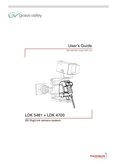
LDK 5481 + LDK 4700 User's Guide - Grass Valley
LDK 5481 + LDK 4700 User's Guide - Grass Valley
LDK 5481 + LDK 4700 User's Guide - Grass Valley

Create successful ePaper yourself
Turn your PDF publications into a flip-book with our unique Google optimized e-Paper software.
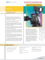
<strong>LDK</strong> <strong>5481</strong> + <strong>LDK</strong> <strong>4700</strong><br />
SD DigiLink camera system<br />
User’s <strong>Guide</strong><br />
3922 496 30541 August 2007 v5.0
<strong>LDK</strong> <strong>5481</strong> + <strong>LDK</strong> <strong>4700</strong> User’s <strong>Guide</strong> ii<br />
Declaration of Conformity<br />
We, <strong>Grass</strong> <strong>Valley</strong> Nederland B.V., Kapittelweg 10, 4827 HG Breda, The Netherlands, declare<br />
under our sole responsibility that this product is in compliance with the following standards:<br />
- EN60950-1 : Safety<br />
- EN55103-1: EMC (Emission)<br />
- EN55103-2: EMC (Immunity)<br />
following the provisions of:<br />
FCC Class A Statement<br />
Copyright<br />
Trademarks<br />
Website<br />
a. the Safety Directives 73/23//EEC and 93/68/EEC<br />
b. the EMC Directives 89/336/EEC and 93/68/EEC<br />
This product generates, uses, and can radiate radio frequency energy and if not installed and<br />
used in accordance with the instructions, may cause interference to radio communications.<br />
It has been tested and found to comply with the limits for a class A digital device pursuant to<br />
part 15 of the FCC rules, which are designed to provide reasonable protection against such<br />
interference when operated in a commercial environment.<br />
Operation of this product in a residential area is likely to cause interference in which case the<br />
user at his own expense will be required to take whatever measures may be required to correct<br />
the interference.<br />
Copyright <strong>Grass</strong> <strong>Valley</strong> Nederland B.V. 2007. Copying of this document and giving it to others,<br />
and the use or communication of the contents thereof, are forbidden without express authority.<br />
Offenders are liable to the payment of damages. All rights are reserved in the event of the grant<br />
of a patent or the registration of a utility model or design. Liable to technical alterations in the<br />
course of further development.<br />
<strong>Grass</strong> <strong>Valley</strong> and Infinity are trademarks of <strong>Grass</strong> <strong>Valley</strong>, Inc. All other tradenames referenced are<br />
service marks, trademarks, or registered trademarks of their respective companies.<br />
Visit the <strong>Grass</strong> <strong>Valley</strong> public website to download the latest user’s guide updates and additional<br />
information about your broadcast product:<br />
www.thomsongrassvalley.com
<strong>LDK</strong> <strong>5481</strong> + <strong>LDK</strong> <strong>4700</strong> User’s <strong>Guide</strong> i<br />
Table of contents<br />
Chapter 1 – DigiLink system<br />
1.1 Introduction . . . . . . . . . . . . . . . . . . . . . . . . . . . . . . . . . . . . . . . . . . . . . . . . . . . . . . . . 1-1<br />
1.2 Accessories . . . . . . . . . . . . . . . . . . . . . . . . . . . . . . . . . . . . . . . . . . . . . . . . . . . . . . . . 1-1<br />
1.3 Compatibility . . . . . . . . . . . . . . . . . . . . . . . . . . . . . . . . . . . . . . . . . . . . . . . . . . . . . . . 1-2<br />
1.4 Configurations . . . . . . . . . . . . . . . . . . . . . . . . . . . . . . . . . . . . . . . . . . . . . . . . . . . . . . 1-2<br />
1.4.1 Digilink system SDI coax configuration . . . . . . . . . . . . . . . . . . . . . . . . . . . . . . 1-2<br />
1.4.2 DigiLink system multicore configuration . . . . . . . . . . . . . . . . . . . . . . . . . . . . . 1-3<br />
1.4.3 Stand alone SDI coax configuration . . . . . . . . . . . . . . . . . . . . . . . . . . . . . . . . . 1-4<br />
1.4.4 Stand alone multicore configuration . . . . . . . . . . . . . . . . . . . . . . . . . . . . . . . . 1-4<br />
1.4.5 DigiLink system hybrid fiber configuration . . . . . . . . . . . . . . . . . . . . . . . . . . . 1-5<br />
1.4.6 DigiLink system dual fiber configuration . . . . . . . . . . . . . . . . . . . . . . . . . . . . . 1-5<br />
1.5 Intercom . . . . . . . . . . . . . . . . . . . . . . . . . . . . . . . . . . . . . . . . . . . . . . . . . . . . . . . . . . . 1-6<br />
Chapter 2 – DigiLink Adapter<br />
2.1 Specifications. . . . . . . . . . . . . . . . . . . . . . . . . . . . . . . . . . . . . . . . . . . . . . . . . . . . . . . 2-5<br />
2.2 Dimensions . . . . . . . . . . . . . . . . . . . . . . . . . . . . . . . . . . . . . . . . . . . . . . . . . . . . . . . . 2-6<br />
2.3 Compatibility . . . . . . . . . . . . . . . . . . . . . . . . . . . . . . . . . . . . . . . . . . . . . . . . . . . . . . . 2-6<br />
2.4 Controls . . . . . . . . . . . . . . . . . . . . . . . . . . . . . . . . . . . . . . . . . . . . . . . . . . . . . . . . . . . 2-7<br />
2.4.1 Powering the camera. . . . . . . . . . . . . . . . . . . . . . . . . . . . . . . . . . . . . . . . . . . . 2-7<br />
2.5 Attaching the <strong>LDK</strong> <strong>5481</strong> adapter to a camera head. . . . . . . . . . . . . . . . . . . . . . . . . 2-8<br />
2.6 Mounting a script board . . . . . . . . . . . . . . . . . . . . . . . . . . . . . . . . . . . . . . . . . . . . . . 2-9<br />
2.7 Adapter connectors . . . . . . . . . . . . . . . . . . . . . . . . . . . . . . . . . . . . . . . . . . . . . . . . . 2-10<br />
2.7.1 SDI video output connector . . . . . . . . . . . . . . . . . . . . . . . . . . . . . . . . . . . . . . 2-11<br />
2.7.2 SDI video input connector . . . . . . . . . . . . . . . . . . . . . . . . . . . . . . . . . . . . . . . 2-11<br />
2.7.3 Multicore connector. . . . . . . . . . . . . . . . . . . . . . . . . . . . . . . . . . . . . . . . . . . . 2-12<br />
2.7.4 Hybrid fiber connector . . . . . . . . . . . . . . . . . . . . . . . . . . . . . . . . . . . . . . . . . . 2-13<br />
2.7.5 Video signal (VF) output connector . . . . . . . . . . . . . . . . . . . . . . . . . . . . . . . . 2-13<br />
2.7.6 Video signal (CVBS) output connector . . . . . . . . . . . . . . . . . . . . . . . . . . . . . . 2-13<br />
2.7.7 Intercom headset connector . . . . . . . . . . . . . . . . . . . . . . . . . . . . . . . . . . . . . 2-14<br />
2.7.8 LCP / Fiber power connector . . . . . . . . . . . . . . . . . . . . . . . . . . . . . . . . . . . . . 2-14<br />
2.7.9 DC power output socket . . . . . . . . . . . . . . . . . . . . . . . . . . . . . . . . . . . . . . . . 2-15<br />
2.7.10 DC power input socket . . . . . . . . . . . . . . . . . . . . . . . . . . . . . . . . . . . . . . . . . 2-15<br />
2.7.11 Script light power supply socket . . . . . . . . . . . . . . . . . . . . . . . . . . . . . . . . . . 2-16<br />
2.8 Install menu . . . . . . . . . . . . . . . . . . . . . . . . . . . . . . . . . . . . . . . . . . . . . . . . . . . . . . . 2-17<br />
Chapter 3 – Base unit<br />
3.1 Specifications. . . . . . . . . . . . . . . . . . . . . . . . . . . . . . . . . . . . . . . . . . . . . . . . . . . . . . . 3-8<br />
3.2 Dimensions . . . . . . . . . . . . . . . . . . . . . . . . . . . . . . . . . . . . . . . . . . . . . . . . . . . . . . . . 3-9<br />
3.3 Controls and indicators . . . . . . . . . . . . . . . . . . . . . . . . . . . . . . . . . . . . . . . . . . . . . . 3-10<br />
3.3.1 Powering the base unit . . . . . . . . . . . . . . . . . . . . . . . . . . . . . . . . . . . . . . . . . 3-10<br />
3.3.2 Indicators . . . . . . . . . . . . . . . . . . . . . . . . . . . . . . . . . . . . . . . . . . . . . . . . . . . . 3-10<br />
3.3.3 Set-up items . . . . . . . . . . . . . . . . . . . . . . . . . . . . . . . . . . . . . . . . . . . . . . . . . 3-10<br />
3.4 Connecting the studio signalling . . . . . . . . . . . . . . . . . . . . . . . . . . . . . . . . . . . . . . 3-12<br />
3.4.1 Call and On-air signals . . . . . . . . . . . . . . . . . . . . . . . . . . . . . . . . . . . . . . . . . . 3-12
<strong>LDK</strong> <strong>5481</strong> + <strong>LDK</strong> <strong>4700</strong> User’s <strong>Guide</strong> ii<br />
3.5 DigiLink base unit connectors. . . . . . . . . . . . . . . . . . . . . . . . . . . . . . . . . . . . . . . . . 3-14<br />
3.5.1 Setup switches . . . . . . . . . . . . . . . . . . . . . . . . . . . . . . . . . . . . . . . . . . . . . . . 3-15<br />
3.5.2 Audio out connector. . . . . . . . . . . . . . . . . . . . . . . . . . . . . . . . . . . . . . . . . . . . 3-15<br />
3.5.3 External video input connector . . . . . . . . . . . . . . . . . . . . . . . . . . . . . . . . . . . 3-16<br />
3.5.4 Reference input connector . . . . . . . . . . . . . . . . . . . . . . . . . . . . . . . . . . . . . . 3-16<br />
3.5.5 Teleprompter input connector . . . . . . . . . . . . . . . . . . . . . . . . . . . . . . . . . . . . 3-16<br />
3.5.6 Y, Pr, Pb output connectors . . . . . . . . . . . . . . . . . . . . . . . . . . . . . . . . . . . . . . 3-17<br />
3.5.7 SDI Camera connectors . . . . . . . . . . . . . . . . . . . . . . . . . . . . . . . . . . . . . . . . . 3-17<br />
3.5.8 CVBS output connector . . . . . . . . . . . . . . . . . . . . . . . . . . . . . . . . . . . . . . . . . 3-17<br />
3.5.9 SDI video output connectors . . . . . . . . . . . . . . . . . . . . . . . . . . . . . . . . . . . . . 3-18<br />
3.5.10 RS-232/RS-422 control connector . . . . . . . . . . . . . . . . . . . . . . . . . . . . . . . . . 3-18<br />
3.5.11 Mains power supply input socket . . . . . . . . . . . . . . . . . . . . . . . . . . . . . . . . . 3-18<br />
3.5.12 Auxiliary connector. . . . . . . . . . . . . . . . . . . . . . . . . . . . . . . . . . . . . . . . . . . . . 3-19<br />
3.5.13 DC power output connector . . . . . . . . . . . . . . . . . . . . . . . . . . . . . . . . . . . . . 3-19<br />
3.5.14 Multicore connector. . . . . . . . . . . . . . . . . . . . . . . . . . . . . . . . . . . . . . . . . . . . 3-20<br />
3.5.15 Hybrid fiber connector . . . . . . . . . . . . . . . . . . . . . . . . . . . . . . . . . . . . . . . . . . 3-20
<strong>LDK</strong> <strong>5481</strong> + <strong>LDK</strong> <strong>4700</strong> User’s <strong>Guide</strong> | DigiLink system 1-1<br />
Chapter 1<br />
DigiLink system<br />
1.1 Introduction<br />
1.2 Accessories<br />
v4.0<br />
The DigiLink system consists of an <strong>LDK</strong> <strong>5481</strong> camera adapter and an <strong>LDK</strong> <strong>4700</strong> base unit for<br />
use with <strong>Grass</strong> <strong>Valley</strong> standard definition (SDTV) camera heads. The system features digital<br />
signal processing and digital transmission of all signals between the camera head and base<br />
unit to ensure there is no loss of quality.<br />
As well as delivering high-quality 10-bit SDI video and audio of CD quality, the bidirectional<br />
digital transmission system carries teleprompter, external video for viewfinder, intercom,<br />
control and tally signals, embedded genlock and private data signals. All these signals are<br />
embedded in the SDI signal streams.<br />
The flexible system configuration makes DigiLink the ideal companion for <strong>Grass</strong> <strong>Valley</strong> cameras<br />
in many environments. Depending on the application and cable lengths needed, the system<br />
can utilize low-cost coax cables, existing multicore cables or hybrid or dual fiber connections.<br />
Typical applications for DigiLink include educational use or small studios such as local TV<br />
stations, continuity or announcement studios. It is also ideal for use in conference and<br />
parliamentary systems or in high-end surveillance. The camera with DigiLink adapter can also<br />
operate as a stand-alone unit by using its VTR output.<br />
The following DigiLink accessories are available:<br />
RS-232 powerline cable <strong>LDK</strong> 8120/02, <strong>LDK</strong> 8120/10, <strong>LDK</strong>8120/25<br />
RS-422 powerline cable <strong>LDK</strong> 8121/02, <strong>LDK</strong> 8120/10, <strong>LDK</strong>8120/25<br />
Headset dynamic XLR-5 with double muff <strong>LDK</strong> 8111/37<br />
DC power supply 100W (2-out) <strong>LDK</strong> 5901/00<br />
Local Control Panel LCP 100 <strong>LDK</strong> 5201<br />
Operational Control Panel OCP 400 <strong>LDK</strong> 4640/10
<strong>LDK</strong> <strong>5481</strong> + <strong>LDK</strong> <strong>4700</strong> User’s <strong>Guide</strong> | DigiLink system 1-2<br />
1.3 Compatibility<br />
v4.0<br />
☞ Note<br />
If you wish to control your camera locally, you can connect an OCP 400 to the RS-232<br />
connector of the camera. When an OCP 400 panel is used with the DigiLink system, C2IP<br />
functions (e.g. file management) are not supported by the system.<br />
The <strong>LDK</strong> <strong>5481</strong> adapter is backwards compatible with existing <strong>LDK</strong> 5480 breakout boxes and<br />
can be connected to them as described in the <strong>LDK</strong> 5480 User’s <strong>Guide</strong>.<br />
1.4 Configurations<br />
1.4.1 Digilink system SDI coax configuration<br />
A camera head with an <strong>LDK</strong> <strong>5481</strong>/00 adapter can be connected to the <strong>LDK</strong> <strong>4700</strong>/00 base unit<br />
using two coax SDI cables. The maximum length of cable that can be used is 250m (820 ft).<br />
High quality coax cable should be used (for example, Belden 1694A). The DC power supply<br />
for the camera is supplied directly to the adapter by an optional local power supply or by the<br />
base unit (using a DC power cable).<br />
Figure 1-1. DigiLink system SDI coax connection<br />
Clear A 1 Clear<br />
Star 4P B 2 ND1/4<br />
Star 6P C 3 ND1/16<br />
Soft Focus D 4 ND1/64<br />
Power<br />
on<br />
SD Camera head<br />
P wel<br />
<strong>LDK</strong> <strong>5481</strong>/00<br />
DigiLink Adapter<br />
Smart<br />
card<br />
optional <strong>LDK</strong> 5901<br />
DC power supply<br />
2x coax cable<br />
max. length 250m. (820ft.)<br />
optional DC power cable<br />
OCP 400/10<br />
<strong>LDK</strong> <strong>4700</strong>/10 DigiLink Base Unit<br />
Ready On-ai r<br />
RS-422 with<br />
powerline <strong>LDK</strong>8121/xx<br />
max. length 25m. (82ft.)<br />
mains power
<strong>LDK</strong> <strong>5481</strong> + <strong>LDK</strong> <strong>4700</strong> User’s <strong>Guide</strong> | DigiLink system 1-3<br />
v4.0<br />
☞ Note<br />
When a DC power cable is used to power the camera from the base unit, refer to section<br />
3.5.13 for the pin layout of the DC connector. The maximum length of the cable depends on<br />
the type of cable and the power used by the camera. The table below is an indication of the<br />
cable lengths that can be used.<br />
Table 1-2. cable length indication for DC power cable<br />
Always use a power cable from the portable power cables category, type W, G, G-GC or PPE.<br />
The cable must be listed in accordance with NEC article 400 of ANSI/NFPA70.<br />
1.4.2 DigiLink system multicore configuration<br />
☞ Note<br />
listed cable<br />
type<br />
A camera head with an <strong>LDK</strong> <strong>5481</strong>/00 adapter can be connected to the <strong>LDK</strong> <strong>4700</strong>/10 base unit<br />
using multicore cable. The maximum length of cable that can be used is 75 m (250 ft). The<br />
base unit can supply power for the camera via the multicore cable. The power consumption<br />
of the camera may reduce the maximum length of cable that can be used, so alternatively, the<br />
power for the camera can be supplied directly to the adapter from the optional <strong>LDK</strong> 5901<br />
power supply.<br />
Figure 1-3. DigiLink system multicore connection<br />
cable cross<br />
section<br />
max. length<br />
(3A/40W)<br />
AWG 20 0.75 mm2 50 m 30 m<br />
AWG 18 1.0 mm 2<br />
75 m 45 m<br />
AWG 16 1.3 mm2 125 m 75 m<br />
Clear A 1 Clear<br />
Star 4P B 2 ND1/4<br />
Star 6P C 3 ND1/16<br />
Soft Focus D 4 ND1/64<br />
Power<br />
on<br />
SD Camera head<br />
P wel<br />
<strong>LDK</strong> <strong>5481</strong>/00<br />
DigiLink Adapter<br />
Smart<br />
card<br />
optional <strong>LDK</strong> 5901<br />
DC power supply<br />
26-pin CCZ-A Multicore cable<br />
max. length 75m (250ft.)<br />
OCP 400/10<br />
max. length<br />
(5A/60W)<br />
<strong>LDK</strong> <strong>4700</strong>/00 DigiLink Base Unit<br />
Always use a listed 26-pin CCZ-A multicore cable compliant with EBU N21 (for example, Draka<br />
multicore camera cable type 755-2 PVC.)<br />
Ready On-ai r<br />
RS-422 with<br />
powerline <strong>LDK</strong>8121/xx<br />
max. length 25m. (82ft.)<br />
mains power
<strong>LDK</strong> <strong>5481</strong> + <strong>LDK</strong> <strong>4700</strong> User’s <strong>Guide</strong> | DigiLink system 1-4<br />
1.4.3 Stand alone SDI coax configuration<br />
v4.0<br />
A camera head with an <strong>LDK</strong> <strong>5481</strong>/00 adapter can be connected to a recorder unit using an<br />
SDI coax cable. Only the SDI signal is passed via the coax cable. The maximum length of cable<br />
that can be used is 300 m (1000 ft). High quality coax cable should be used (for example,<br />
Belden 1694A). The DC power supply for the camera is supplied directly to the adapter.<br />
Figure 1-4. Stand alone SDI coax configuration<br />
1.4.4 Stand alone multicore configuration<br />
☞ Note<br />
SD Camera head<br />
A camera head with an <strong>LDK</strong> <strong>5481</strong>/00 adapter can be connected to a recorder using a<br />
multicore cable. Power can be supplied by the recorder via the multicore cable or directly to<br />
the adapter itself. To avoid degradation in the video signal, the maximum cable length is<br />
restricted to 5 m (17 ft) when the component outputs are used in the recorder.<br />
If the recorder uses the SDI signals, then the maximum length of cable depends on the ability<br />
of the recorder unit to supply sufficient power to the camera. When the adapter is powered<br />
directly the maximum length is 100 m (330 ft). With minimum power supplied from the<br />
recorder unit the maximum length is 25 m (80 ft).<br />
Figure 1-5. Stand alone multicore configuration<br />
SD Camera head<br />
Clear A 1 Clear<br />
Star 4P B 2 ND1/4<br />
Star 6P C 3 ND1/16<br />
Soft Focus D 4 ND1/64<br />
Power<br />
on<br />
P wel<br />
Clear A 1 Clear<br />
Star 4P B 2 ND1/4<br />
Star 6P C 3 ND1/16<br />
Soft Focus D 4 ND1/64<br />
Power<br />
on<br />
P wel<br />
<strong>LDK</strong> <strong>5481</strong>/00<br />
DigiLink Adapter<br />
Smart<br />
card<br />
optional <strong>LDK</strong> 5901<br />
DC power supply<br />
<strong>LDK</strong> <strong>5481</strong>/00<br />
DigiLink Adapter<br />
Smart<br />
card<br />
optional <strong>LDK</strong> 5901<br />
DC power supply<br />
VTR on/off ! Batt Tape nd/re<br />
LCP 100 local control panel<br />
Operate<br />
VTR start/stop<br />
VTR on/off ! Batt Tape nd/re<br />
LCP 100 local control panel<br />
Operate<br />
Function<br />
Gain<br />
Black<br />
SDI coax cable<br />
LCP 100<br />
26-pin CCZ-A Multicore cable<br />
VTR start/stop<br />
Function<br />
Gain<br />
Black<br />
LCP 100<br />
Video recorder<br />
Video recorder<br />
Always use a listed 26-pin CCZ-A multicore cable compliant with EBU N21 (for example, Draka<br />
multicore camera cable type 755-2 PVC)
<strong>LDK</strong> <strong>5481</strong> + <strong>LDK</strong> <strong>4700</strong> User’s <strong>Guide</strong> | DigiLink system 1-5<br />
1.4.5 DigiLink system hybrid fiber configuration<br />
v4.0<br />
A camera head with an <strong>LDK</strong> <strong>5481</strong>/20 fiber adapter can be connected to the <strong>LDK</strong> <strong>4700</strong>/20<br />
base unit using a hybrid fiber cable that carries both signal and power. The maximum cable<br />
length that can be used is 100 m (330 ft). The power consumption of the camera may reduce<br />
the maximum length of cable that can be used, so alternatively, the power for the camera can<br />
be supplied directly to the adapter from the optional <strong>LDK</strong> 5901 power supply.<br />
Figure 1-6. DigiLink system hybrid fiber connection<br />
Clear A 1 Clear<br />
Star 4P B 2 ND1/4<br />
Star 6P C 3 ND1/16<br />
Soft Focus D 4 ND1/64<br />
Power<br />
on<br />
SD camera head<br />
P wel<br />
<strong>LDK</strong> <strong>5481</strong>/20<br />
DigiLink adapter<br />
Hybrid fiber cable<br />
max. 100 m (330 ft)<br />
1.4.6 DigiLink system dual fiber configuration<br />
Smart<br />
card<br />
optional <strong>LDK</strong> 5901<br />
DC power supply<br />
A camera head with an <strong>LDK</strong> <strong>5481</strong>/20 fiber adapter can be connected to the <strong>LDK</strong> <strong>4700</strong>/20<br />
base unit using a dual fiber cable. The maximum cable length that can be used is 5,000 m<br />
(16,400 ft). The camera adapter must be powered locally by the optional <strong>LDK</strong> 5901 DC power<br />
supply.<br />
Figure 1-7. DigiLink system dual fiber connection<br />
Clear A 1 Clear<br />
Star 4P B 2 ND1/4<br />
Star 6P C 3 ND1/16<br />
Soft Focus D 4 ND1/64<br />
Power<br />
on<br />
Power<br />
on<br />
SD camera head<br />
P wel<br />
P wel<br />
<strong>LDK</strong> <strong>5481</strong>/20<br />
DigiLink adapter<br />
Smart<br />
card<br />
optional <strong>LDK</strong> 5901<br />
DC power supply<br />
Hybrid Dual fiber cable<br />
max. max. 5,000 100 m (16,400 (330 ft) ft)<br />
OCP 400/10<br />
OCP 400/10<br />
<strong>LDK</strong> <strong>4700</strong>/20 DigiLink Base unit<br />
Ready On-ai r<br />
RS-422 with<br />
powerline <strong>LDK</strong>8121/xx<br />
max. 25 m (82 ft)<br />
<strong>LDK</strong> <strong>4700</strong>/20 DigiLink Base unit<br />
Ready On-ai rr<br />
RS-422 with<br />
powerline <strong>LDK</strong>8121/xx<br />
max. 25 m (82 ft)<br />
Mains power<br />
Mains power
<strong>LDK</strong> <strong>5481</strong> + <strong>LDK</strong> <strong>4700</strong> User’s <strong>Guide</strong> | DigiLink system 1-6<br />
1.5 Intercom<br />
v4.0<br />
An intercom channel connects the base unit to the camera operator's headset. The operator's<br />
intercom microphone signal is sent to the base unit. The headset can be connected to the 5<br />
pin XLR headset connector at the back of the DigiLink adapter. For the connector and detailed<br />
pin descriptions refer to chapter 2.7.7.<br />
A conversation is started when the camera operator presses the VTR Start button at the front<br />
of the camera or the VTR button on the lens. The function and behaviour of this button can be<br />
defined in the INSTALL menu of the camera. Refer to the camera’s user’s guide.<br />
The volume of the headset earmuffs can be adjusted by turning the audio volume knob at the<br />
front (right side) of the camera.<br />
Intercom configuration<br />
The sidetone volume level (feedback signal from the microphone to the earmuffs) can be<br />
adjusted withthe INSTALL/INTERCOM/SIDETONE function n the camera (available only when<br />
a 4-wire connection is used).<br />
Depending on the type of microphone the following items can be set in the INSTALL/<br />
INTERCOM menu in the camera:<br />
Microphone gain level (0 or +40 dB) with the CAM.MIC_GAIN function;<br />
Microphone power can be switched on or off with the CAM.MIC_POWER function.<br />
Both 2-wire and 4-wire intercom connections can be used. On the base unit, set the setup<br />
switch S1 in the Off-position when a 4-wire connection is used and set it in the On-position<br />
when a 2-wire connection is used. Refer to chapter 3.5.2 for the description of the setup<br />
switch.<br />
The following figure shows an overview of the routing of the intercom system. For the<br />
connector and detailed pin descriptions refer to chapter 3.4.<br />
Figure 1-8. Schematic overview of the intercom routing<br />
Mic in<br />
-24/-64 dBu<br />
Cam Video<br />
EXT/TP video<br />
Out<br />
0 dBu<br />
DigiLink adapter DigiLink base unit<br />
0 / 40 dB<br />
front volume<br />
Cam SDI OUT<br />
Cam SDI IN<br />
2 w.<br />
4 w.<br />
S1 Off = 4-wire<br />
S1 On = 2-wire<br />
PROD out (4-wire)<br />
PROD in/out (2-wire)<br />
0 dBu<br />
pin 1,9 return<br />
SDI<br />
EXT<br />
TP<br />
PROD in (4-wire)<br />
0 dBu<br />
pin 5, 13 return
<strong>LDK</strong> <strong>5481</strong> + <strong>LDK</strong> <strong>4700</strong> User’s <strong>Guide</strong> | DigiLink Adapter 2-1<br />
Chapter 2<br />
DigiLink Adapter<br />
Important information (English)<br />
Safety Summary<br />
Warnings<br />
v4.0<br />
Read this information carefully before installing or servicing this equipment and retain them for<br />
future reference. Read and comply with the warning and caution notices that appear in the<br />
manual.<br />
Any changes or modifications not expressly approved in this manual could void your authority<br />
to operate this equipment.<br />
This informaton is intended as a guide for trained and qualified personnel who are aware of<br />
the dangers involved in handling potentially hazardous electrical/electronic equipment. It is<br />
not intended to contain a complete list of all safety precautions which should be observed by<br />
personnel in using this or other electronic equipment.<br />
The installation of this equipment involves risks both to personnel and equipment and must<br />
be performed only by qualified personnel exercising due care.<br />
During installation and operation of this equipment, local building safety and fire protection<br />
standards must be observed.<br />
Whenever it is likely that safe operation is impaired, the apparatus must be made inoperative<br />
and secured against any unintended operation. The appropriate servicing authority must then<br />
be informed. For example, safety is likely to be impaired if the apparatus fails to perform the<br />
intended function or shows visible damage.<br />
Warnings indicate danger that requires correct procedures or practices to prevent death or<br />
injury to personnel.<br />
Do not modify this equipment.<br />
Installation of this equipment must only be performed by qualified personnel.<br />
Do not use any accessories other than those recommended by the manufacturer.<br />
In case of an emergency ensure that the power is disconnected.
<strong>LDK</strong> <strong>5481</strong> + <strong>LDK</strong> <strong>4700</strong> User’s <strong>Guide</strong> | DigiLink Adapter 2-2<br />
Cautions<br />
v4.0<br />
There are no user servicable parts inside. Refer servicing to qualified personnel only or<br />
contact your local <strong>Grass</strong> <strong>Valley</strong> representative.<br />
Cautions indicate procedures or practices that should be followed to prevent damage or<br />
destruction to equipment or property.<br />
Always switch off the camera before changing the power supply.<br />
Be extremely careful with the connectors between the camera head and the adapter. Do<br />
not allow the guide pins to damage the pins of the connector. Follow these steps in the<br />
order given. Tightening the screws in the wrong order could result in mechanical damage<br />
to the camera. Loosening the screws in the wrong order could result in mechanical<br />
damage to the camera.<br />
To prevent risk of overheating, ventilate the units correctly.<br />
Do not subject the unit to severe shocks or vibration.<br />
Do not expose the unit to extremes of temperature.<br />
Do not leave the unit in direct sunlight or close to heating appliances for extended periods.<br />
Avoid very damp places. If the environment is wet or damp a rain cover must be used to<br />
protect the unit.<br />
Wichtige Hinweise (Deutsch)<br />
Lesen Sie bitte diese Hinweise genau bevor Sie diese Apparatur installieren und erhalten Sie<br />
Sie für künftiges Nachslagen. Beachten und Lesen Sie alle mit “Achtung” und “Vorsicht”<br />
gekennzeichneten Warnhinweise.<br />
Änderungen haben zur Folge, dass die Garantie ungültig wird und der Benutzer für etwaige<br />
durch die veränderte Ausrüstung verursachte Störungen haftbar gemacht werden könnte.<br />
Sicherheit (Zusammenfassung)<br />
Diese Informationen sind als Leitfaden für qualifiziertes Fachpersonal gedacht, das die<br />
Gefahren beim Umgang mit potenziell gefährlicher elektrischer/elektronischer Ausrüstung<br />
kennt. Es handelt sich dabei nicht um eine vollständige Zusammenstellung aller<br />
Sicherheitsvorkehrungen, die beim Gebrauch dieser oder anderer elektronischer Geräte zu<br />
beachten sind.<br />
Die Montage, Wartung und Instandsetzung dieser Ausrüstung ist mit Risiken für Personal und<br />
Ausrüstung verbunden und darf nur von qualifiziertem Personal vorgenommen werden, wobei<br />
mit der nötigen Sorgfalt vorzugehen ist.<br />
Mit der Montage, Bedienung, Instandhaltung oder Instandsetzung dieser Ausrüstung<br />
betrauten Personen wird dringend geraten, sich mit der Theorie und Praxis der Ersten Hilfe<br />
vertraut zu machen.<br />
Beim Einbau und Betrieb dieser Ausrüstung müssen die örtlichen Gebäudesicherheits- und<br />
Brandschutzvorschriften beachtet werden. Vor dem Anschluss der Ausrüstung an die<br />
Stromversorgung der Anlage muss überprüft werden, ob der Schutzleiter intakt ist.
<strong>LDK</strong> <strong>5481</strong> + <strong>LDK</strong> <strong>4700</strong> User’s <strong>Guide</strong> | DigiLink Adapter 2-3<br />
Vorsicht!<br />
Achtung!<br />
v4.0<br />
Wenn eine Beeinträchtigung des sicheren Betriebs wahrscheinlich ist, muss das Gerät außer<br />
Betrieb gesetzt und gegen ungewollten Betrieb gesichert werden. Dann muss der zuständige<br />
Kundendienst benachrichtigt werden. Eine Beeinträchtigung der Sicherheit ist zum Beispiel<br />
dann wahrscheinlich, wenn das Gerät nicht wie vorgesehen funktioniert oder einen sichtbaren<br />
Schaden aufweist.<br />
Mit “Vorsicht” wird auf eine Gefahr hingewiesen, die korrekte Arbeits- oder Verfahrensweisen<br />
erfordert, um Tod oder Verletzung zu verhindern.<br />
An dieser Ausrüstung dürfen keine Änderungen vorgenommen werden;<br />
Die Montage dieser Ausrüstung darf nur von Fachpersonal vorgenommen werden;<br />
Es sollen nur von den Hersteller empfohlene Zubehöre verwendet werden;<br />
Bei Eintreten eines Notfalls unbedingt die Stromzufuhr abschalten;<br />
Dieses Produkt enthält keine Anwenderteile. Reparatur und Wartung nur von<br />
qualifiziertem Fachpersonal vornehmen lassen oder nehmen Sie Kontakt auf mit Ihrem<br />
<strong>Grass</strong> <strong>Valley</strong> Vertretene;<br />
Mit “Achtung” werden Arbeitsanweisungen gekennzeichnet, die zu befolgen sind, um eine<br />
Beschädigung oder Zerstörung der Ausrüstung bzw. von Eigentum zu verhindern.<br />
Die Kamera vor dem Wechsel der Stromversorgung immer ausschalten;<br />
Stecker zwischen Kamerakopf und Adapter mit äußerster Vorsicht handhaben. Darauf<br />
achten, dass die Steckerstifte nicht durch die Führungsstifte beschädigt werden.<br />
Um einer Überhitzungsgefahr vorzubeugen, ist das Produkt korrekt zu belüften;<br />
Dieses Produkt darf nicht an extremen stöße oder Zittern ausgesetzt werden;<br />
Dieses Produkt darf nicht an extremen Temperaturen ausgesetzt werden;<br />
Nicht langfristig in direktem Sonnenlicht oder in der Nähe von Heizgeräte zurücklassen.<br />
Vermeide feuchtigen Plätze. Wenn die Umgebung nass oder feucht ist, muss ein<br />
Regenüberzug verwendet werden um das Gerät zu schützen.
<strong>LDK</strong> <strong>5481</strong> + <strong>LDK</strong> <strong>4700</strong> User’s <strong>Guide</strong> | DigiLink Adapter 2-4<br />
Fiber optic transmission units<br />
v4.0<br />
A yellow coloured CLASS 1 LASER PRODUCT label is located on top of the fiber optic<br />
connector on the rear panel of the adapter.<br />
Laser safety statement (Europe)<br />
Fiber optic transmission units are classified as a “CLASS 1 Laser Product” according to<br />
EN 60825-1, Safety of Laser products. Class 1 laser products are considered safe and do not<br />
result in biological hazard if used according to the instructions.<br />
Laser safety statement (US)<br />
Fiber optic transmission units are classified as a “CLASS 1 Laser Product” according to<br />
21CFR 1040.10 of the US Food and Drug Administration (FDA) Center for Devices and<br />
Radiological Health.<br />
WARNING<br />
Use of controls, adjustments or performance of procedures other than those specified<br />
herein may result in hazardous radiation exposure.<br />
Fiber optic cable precautions<br />
CLASS 1<br />
LASER PRODUCT<br />
LASER KLASSE 1<br />
PRODUKT<br />
To ensure proper use of this product, please read this instruction manual carefully and<br />
retain for future reference. Should the unit ever require maintenance, contact an<br />
authorized service location.<br />
Fiber optic cables and connectors are easily damaged; take the following percautions into<br />
account:<br />
Do not bend the cable beyond the minimum bend range specified for the cable.<br />
Avoid kinks or sharp bends in the cable.<br />
Avoid subjecting the cable to a high tension force.<br />
Do not twist the cable when connecting it to equipment.<br />
Insert connectors straight and fully into their corresponding sockets.<br />
In fiber optic cable systems always put the dust caps on cable and panel connectors<br />
immediately after disconnecting a cable. Keep the dust caps clean.
<strong>LDK</strong> <strong>5481</strong> + <strong>LDK</strong> <strong>4700</strong> User’s <strong>Guide</strong> | DigiLink Adapter 2-5<br />
2.1 Specifications<br />
v4.0<br />
The DigiLink camera adapter is available in two versions:<br />
The <strong>LDK</strong> <strong>5481</strong>/00 version has a 26-pin multicore connector and two SDI coax connectors<br />
to connect to an <strong>LDK</strong> <strong>4700</strong>/00 or <strong>LDK</strong> <strong>4700</strong>/10 base unit;<br />
The <strong>LDK</strong> <strong>5481</strong>/20 version has a hybrid fiber connector to connect to the <strong>LDK</strong> <strong>4700</strong>/20<br />
DigiLink fiber adapter.<br />
When ordering, you specify the version you require.<br />
Item Value<br />
Power requirements 12 VDC<br />
Power consumption typical 12 W<br />
Operating temperatures -20 to +45°C (-4 to +113°F)<br />
Storage temperatures -20 to +60°C (-4 to +140°F)<br />
Weight (approx.) 1.5 kg (3.3 lbs)<br />
Dimensions 105 mm (L) x 120 mm (W) x 225 mm (H) mm without<br />
handgrip<br />
Power input 12 VDC XLR-4 male (or multicore cable)<br />
Power output 12 VDC 1.5A; 4-pin Hirose<br />
CVBS out (VF/EXT/TP) 1 Vpp; 75 Ohm; BNC<br />
Viewfinder output (CVBS/EXT/TP) 1 Vpp; 75 Ohm; BNC<br />
LCP connector for connecting an LCP 100 local control panel;<br />
12-pin Hirose<br />
<strong>LDK</strong> <strong>5481</strong>/00 version (multicore/coax)<br />
Multicore connection 26-pin EBU N21 multicore connector<br />
SDI Video output SMPTE 259M, 0.8 Vpp, 270Mb/s; 75 Ohm; BNC<br />
SDI Video input SMPTE 259M, 0.8 Vpp, 270Mb/s; 75 Ohm; BNC<br />
<strong>LDK</strong> <strong>5481</strong>/20 version (fiber version)<br />
DigiLink connection Neutrik hybrid fiber optical connecotor
<strong>LDK</strong> <strong>5481</strong> + <strong>LDK</strong> <strong>4700</strong> User’s <strong>Guide</strong> | DigiLink Adapter 2-6<br />
2.2 Dimensions<br />
2.3 Compatibility<br />
v4.0<br />
Figure 2-1. <strong>LDK</strong> <strong>5481</strong> DigiLink adapter dimension sketch<br />
Before using the <strong>LDK</strong> <strong>5481</strong> DigiLink adapter you must ensure that it is compatible with your<br />
camera head. Camera heads with software version v13.0 and higher are fully compatible and<br />
do not need to be upgraded. Camera heads with software below this version must be<br />
updated.<br />
Older camera heads with data board no. 3922 406 84271 or <strong>LDK</strong> 100 cameras built before 2001 need to be<br />
upgraded. For more information on upgrading your camera contact your <strong>Grass</strong> <strong>Valley</strong> service representative.
<strong>LDK</strong> <strong>5481</strong> + <strong>LDK</strong> <strong>4700</strong> User’s <strong>Guide</strong> | DigiLink Adapter 2-7<br />
2.4 Controls<br />
v4.0<br />
Figure 2-2. <strong>LDK</strong> <strong>5481</strong> adapter controls<br />
2<br />
1<br />
2.4.1 Powering the camera<br />
DC out LCP CVBS VF<br />
1. Power source selection switch<br />
2. Power on indicator (green)<br />
3. Tally indicators (red)<br />
4. Circuit breaker button (fuse)<br />
The power supply for the camera and the adapter (+12 Vdc) is normally supplied either via<br />
the multicore connector or via the DC IN socket. Set the power source selection switch (1) to<br />
the position that corresponds to your chosen method:<br />
LOC: Powered via DC IN socket<br />
REM:Powered via multicore<br />
3<br />
4<br />
The power on indicator (2) lights when power is supplied and the camera power switch is On.<br />
If excessive current flows in the camera or adapter, the circuit breaker (4) trips and shuts off<br />
power to all the units. If this happens, check the units for faults and if necessary take<br />
corrective action before pressing the circuit breaker button to reset the power.
<strong>LDK</strong> <strong>5481</strong> + <strong>LDK</strong> <strong>4700</strong> User’s <strong>Guide</strong> | DigiLink Adapter 2-8<br />
2.5 Attaching the <strong>LDK</strong> <strong>5481</strong> adapter to a camera head<br />
v4.0<br />
The <strong>LDK</strong> <strong>5481</strong> adapter is shorter than a standard adapter. Before attaching the <strong>LDK</strong> <strong>5481</strong><br />
adapter to a camera, the carrying handle must be re-positioned on the camera head using the<br />
mounting bracket supplied with the adapter.<br />
To re-position the carrying handle for a short adapter, proceed as follows:<br />
1. Remove the viewfinder and any other adapter attached to the camera.<br />
2. Unscrew and remove the two screws that attach the front of the carrying handle to the<br />
camera. (For the <strong>LDK</strong> 500: tilt the carrying handle backwards and use your fingertips to<br />
gently unplug the flat cable that connects the zoom control to the connector inside the<br />
camera body.)<br />
☞ Note<br />
The digital zoom control of the <strong>LDK</strong> 500 cannot be used in combination with the <strong>LDK</strong> <strong>5481</strong><br />
adapter. An optional analogue zoom control <strong>LDK</strong> 6113 can be used.<br />
3. Remove the carrying handle from the camera.<br />
4. Use the supplied screws and washers to attach the mounting bracket to the top of the<br />
camera. (Use the screw holes where the handle was previously attached.)<br />
Figure 2-1. Carrying handle replacement<br />
(2x)<br />
Clear A 1 Clea r<br />
Star 4P B 2 ND1/4<br />
Star 6P C 3 ND1/16<br />
Soft Focus D 4 ND1/64<br />
VT R Std. Ext.<br />
Save File Iris<br />
Power<br />
On<br />
Power<br />
Off<br />
Smart<br />
card<br />
(2x)<br />
Clear A 1 Clea r<br />
Star 4P B 2 ND1/4<br />
Star 6P C 3 ND1/16<br />
Soft Focus D 4 ND1/64<br />
VT R Std. Ext.<br />
Save File Iris<br />
Power<br />
Power<br />
On Off<br />
Clear A 1 Clea r<br />
Star 4P B 2 ND1/4<br />
Star 6P C 3 ND1/16<br />
Soft Focus D 4 ND1/64<br />
VT R Std. Ext.<br />
Save File Iris<br />
5. For <strong>LDK</strong> 500: fold the flat cable away into the hollow part of the carrying handle.<br />
Smart<br />
card<br />
6. Place the carrying handle into the recess at the front of the mounting plate and use the<br />
two original screws to secure it in place.<br />
7. Attach the <strong>LDK</strong> <strong>5481</strong> adapter to the camera (refer to section “Attaching an adapter” in the<br />
User’s <strong>Guide</strong> of your camera for further instructions).<br />
(2x)<br />
Power<br />
on<br />
Power<br />
Off<br />
Smart<br />
card
<strong>LDK</strong> <strong>5481</strong> + <strong>LDK</strong> <strong>4700</strong> User’s <strong>Guide</strong> | DigiLink Adapter 2-9<br />
2.6 Mounting a script board<br />
v4.0<br />
To attach the optional script board (<strong>LDK</strong> 6985/21) to the adapter use the special bracket and<br />
screws delivered with the script board. To attach the bracket to the adapter, proceed as<br />
follows:<br />
1. Unscrew and remove the four screws attaching the viewfinder holder to the top of the<br />
adapter.<br />
2. Place the viewfinder holder on top of the script board bracket and align the screw holes.<br />
3. Using the four long screws provided, attach the holder and bracket to the top of the<br />
adapter.<br />
4. The script board can now be mounted onto the bracket.<br />
Figure 2-3. Script board accessory<br />
viewfinder<br />
holder<br />
script board<br />
holder bracket
<strong>LDK</strong> <strong>5481</strong> + <strong>LDK</strong> <strong>4700</strong> User’s <strong>Guide</strong> | DigiLink Adapter 2-10<br />
2.7 Adapter connectors<br />
v4.0<br />
Figure 2-4. DigiLink adapter connector locations<br />
<strong>LDK</strong> <strong>5481</strong>/00<br />
Script light<br />
output<br />
SCRIPTLIGHT POWER<br />
LOC/REM<br />
DC IN<br />
FUSE<br />
DC power<br />
supply input<br />
DC power LCP<br />
output connector<br />
Multicore<br />
connector<br />
CVBS<br />
output<br />
SDI<br />
video out<br />
SDI<br />
SDI<br />
video in<br />
DC out LCP CVBS VF<br />
VF<br />
output<br />
<strong>LDK</strong> <strong>5481</strong>/20<br />
BA<br />
Hybrid fiber<br />
connector<br />
Script light<br />
output<br />
POWER<br />
LOC/REM<br />
DC IN<br />
FUSE<br />
SCRIPTLIGHT<br />
DC power<br />
supply input<br />
Headset<br />
connector<br />
SDI<br />
video out<br />
SDI<br />
SDI<br />
video in
<strong>LDK</strong> <strong>5481</strong> + <strong>LDK</strong> <strong>4700</strong> User’s <strong>Guide</strong> | DigiLink Adapter 2-11<br />
2.7.1 SDI video output connector<br />
v4.0<br />
Figure 2-5. SDI video output connector<br />
BNC connector: panel view (X8)<br />
2.7.2 SDI video input connector<br />
Figure 2-6. SDI video input connector<br />
BNC connector: panel view (X9)<br />
This BNC connector supplies an SDI video output signal<br />
(Y/Cr/Cb 4:2:2) that also includes embedded audio,<br />
intercom and private data signals.<br />
This BNC connector receives an SDI video input from<br />
the base unit.<br />
Reference, teleprompter and external video signals are<br />
embedded in the stream together with intercom,<br />
control and private data signals.
<strong>LDK</strong> <strong>5481</strong> + <strong>LDK</strong> <strong>4700</strong> User’s <strong>Guide</strong> | DigiLink Adapter 2-12<br />
2.7.3 Multicore connector<br />
v4.0<br />
Figure 2-7. Multicore connector<br />
6<br />
B<br />
5<br />
11 10<br />
17<br />
4<br />
16<br />
22<br />
A<br />
3<br />
9<br />
15<br />
21<br />
8<br />
14<br />
20<br />
24<br />
2<br />
23<br />
1<br />
7<br />
13<br />
19<br />
12<br />
18<br />
26-pin male; panel view<br />
Panel part number: (X6) 3922 040 02571<br />
This multicore connector can be used to<br />
connect either a recorder or a base unit<br />
(<strong>LDK</strong> <strong>4700</strong>/10).<br />
When connected to a recorder it provides the<br />
video outputs, control signals and the camera<br />
microphone signal. DC power can also be<br />
supplied to the camera via this connector.<br />
The connector accepts a playback video signal<br />
for display in the viewfinder. The start/stop<br />
control signal for an external recorder is also<br />
passed via this connector.<br />
A.+ Battery from VTR (+10.7 to +17V)<br />
B.- Battery Ground<br />
1. SDI<br />
2. SDI Return<br />
3. Y Return<br />
4. Y<br />
5. Pr: NTSC 700mV 75% saturated colour bar<br />
Cr: PAL 525mV (EBU N10)<br />
6. Pr/Cr Return<br />
7. Pb: NTSC 700mV 75% saturated colour bar<br />
Cb: PAL 525mV (EBU N10)<br />
8. Pb/Cb Return<br />
9. Cam. Mic. X<br />
10. Cam. Mic. Y<br />
11. Cam. Mic. shield<br />
12. VTR start/stop: +5V = recording; 0V = stop<br />
13. Batt. alarm<br />
14. Power sense<br />
15. Record/Tally<br />
16. Genlock Video/BB return<br />
17. Cable shield (Camera GND to VTR GND)<br />
18. Playback video / Ext. VF<br />
19. Playback video return / Ext. VF return<br />
20. VTR Save<br />
21. Genlock Video/BB<br />
22. Spare<br />
23. RXD, control<br />
24. TXD, control
<strong>LDK</strong> <strong>5481</strong> + <strong>LDK</strong> <strong>4700</strong> User’s <strong>Guide</strong> | DigiLink Adapter 2-13<br />
2.7.4 Hybrid fiber connector<br />
v4.0<br />
Figure 2-8. Hybrid fiber connector<br />
4<br />
B A<br />
3 2<br />
2.7.5 Video signal (VF) output connector<br />
Figure 2-9. Video signal (VF) output connector<br />
2.7.6 Video signal (CVBS) output connector<br />
1<br />
Neutrik OpticalCon® Hybrid Fiber connector<br />
(NO2-4FD-1-R)<br />
BNC connector: panel view<br />
A Fiber IN<br />
B Fiber OUT<br />
1. Power GND<br />
Figure 2-10. Video signal (CVBS) output connector<br />
BNC connector: panel view<br />
2. Power GND sense<br />
3. Power + sense<br />
4. Poweer +<br />
This BNC socket provides a 1.0 Vpp analog output video<br />
signal. This signal can be assigned in the INSTALL<br />
menu of the camera. Either the VF, CVBS, EXT. or TP<br />
signal can be selected.<br />
By default the viewfinder signal is output. Markers and<br />
menus similar to those in the viewfinder can be<br />
superimposed on this signal.<br />
This BNC socket provides a 1.0 Vpp analog output video<br />
signal. This signal can be assigned in the INSTALL<br />
menu of the camera. Either the VF, CVBS, EXT. or TP<br />
signal can be selected.<br />
By default the CVBS signal is output for viewing.
<strong>LDK</strong> <strong>5481</strong> + <strong>LDK</strong> <strong>4700</strong> User’s <strong>Guide</strong> | DigiLink Adapter 2-14<br />
2.7.7 Intercom headset connector<br />
v4.0<br />
Figure 2-11. XLR intercom headset connector<br />
2.7.8 LCP / Fiber power connector<br />
1<br />
5<br />
XLR 5-pin female; panel view (X11)<br />
Figure 2-12. LCP connector<br />
7<br />
8<br />
6<br />
9<br />
12<br />
10<br />
5<br />
1<br />
11<br />
Hirose 12-pin female; panel view<br />
Panel part number: (X5) 2422 026 04355<br />
2<br />
4<br />
4<br />
3<br />
2<br />
3<br />
1. Microphone return<br />
2. Microphone<br />
3. Telephone return<br />
4. Telephone left<br />
5. Telephone right<br />
Microphone level: -64 dBu / -24 dBu switchable<br />
Microphone impedance: >600 Ohm<br />
Telephone level: +6 dBu nominal<br />
Telephone output impedance:
<strong>LDK</strong> <strong>5481</strong> + <strong>LDK</strong> <strong>4700</strong> User’s <strong>Guide</strong> | DigiLink Adapter 2-15<br />
2.7.9 DC power output socket<br />
v4.0<br />
Figure 2-13. DC power and tally output connector<br />
1 2<br />
2.7.10 DC power input socket<br />
4<br />
Hirose 4-pin female; panel view<br />
Panel part number: (X3) 2422 026 04675<br />
3<br />
Caution<br />
The input voltage must not exceed +17 Vdc.<br />
Figure 2-14. DC power input connector<br />
1<br />
2 3<br />
XLR 4-pin male: panel view (X7)<br />
4<br />
1. Power ground<br />
2. On air (+5V, 100 Ohm)<br />
3. Housing<br />
4. +12 Vdc (max. 18W)<br />
Shield of cable directly to the connector housing.<br />
The socket provides access to an internal tally switch.<br />
When the camera is on-air, the contact of the internal<br />
relay is closed.<br />
1. Power ground<br />
2. -Batt sense<br />
3. +Batt sense<br />
4. +10.5 Vdc . . . +17 Vdc<br />
This socket accepts a DC voltage of 12V nominal.<br />
Maximum power consumption 60W.
<strong>LDK</strong> <strong>5481</strong> + <strong>LDK</strong> <strong>4700</strong> User’s <strong>Guide</strong> | DigiLink Adapter 2-16<br />
2.7.11 Script light power supply socket<br />
v4.0<br />
Figure 2-15. Script light power supply output connector<br />
2<br />
1<br />
3<br />
Fischer 3-pin female: panel view<br />
Panel connector number: (X4) 3922 040 02881<br />
1. +12 Vdc (maximum dissipation 3W)<br />
2. Power return<br />
3. Shield
<strong>LDK</strong> <strong>5481</strong> + <strong>LDK</strong> <strong>4700</strong> User’s <strong>Guide</strong> | DigiLink Adapter 2-17<br />
2.8 Install menu<br />
v4.0<br />
The functions shown in the table below appear in the INSTALL menu of the camera head<br />
when an <strong>LDK</strong> <strong>5481</strong> adapter is attached. Refer to the User’s <strong>Guide</strong> of the camera head for more<br />
information on accessing this menu.<br />
Main menu items Purpose<br />
Disable Camera on/off<br />
IR receiver on/off<br />
OnAir Lamp on/off<br />
Intercom set intercom values<br />
Audio set gain and filter<br />
Timing set subcarrier and h-phase<br />
Notch on/off<br />
Aspect ratio select aspect ratio values<br />
Exposure set lighting and clear scan values<br />
Gain preset set gain preset values<br />
Quick Smart Touch on/off<br />
Buttons assign functions to buttons<br />
Video output assign YCrCb or RGB to VTR output<br />
CVBS output assign CVBS, EXT, TP or VF to CVBS output<br />
VF output assign CVBS, EXT, TP or VF to VF output
<strong>LDK</strong> <strong>5481</strong> + <strong>LDK</strong> <strong>4700</strong> User’s <strong>Guide</strong> | DigiLink Adapter 2-18<br />
v4.0
<strong>LDK</strong> <strong>5481</strong> + <strong>LDK</strong> <strong>4700</strong> User’s <strong>Guide</strong> | Base unit 3-1<br />
Chapter 3<br />
Base unit<br />
Important information (English)<br />
Safety Summary<br />
Warnings<br />
v4.0<br />
Read this information carefully before installing this equipment and retain them for future<br />
reference. Read and comply with the warning and caution notices that appear in the manual.<br />
Any changes or modifications not expressly approved in this manual could void your authority<br />
to operate this equipment.<br />
This informaton is intended as a guide for trained and qualified personnel who are aware<br />
of the dangers involved in handling potentially hazardous electrical/electronic equipment.<br />
It is not intended to contain a complete list of all safety precautions which should be<br />
observed by personnel in using this or other electronic equipment.<br />
The installation of this equipment involves risks both to personnel and equipment and<br />
must be performed only by qualified personnel exercising due care.<br />
During installation and operation of this equipment, local building safety and fire<br />
protection standards must be observed.<br />
Before connecting the equipment to the power supply of the installation, the proper<br />
functioning of the protective earth lead of the installation needs to be verified.<br />
Whenever it is likely that safe operation is impaired, the apparatus must be made inoperative<br />
and secured against any unintended operation. The appropriate servicing authority must then<br />
be informed. For example, safety is likely to be impaired if the apparatus fails to perform the<br />
intended function or shows visible damage.<br />
Warnings indicate danger that requires correct procedures or practices to prevent death or<br />
injury to personnel.<br />
Do not modify this equipment;<br />
Installation of this equipment must only be performed by qualified personnel;<br />
Do not use any accessories other than those recommended by the manufacturer;<br />
In case of an emergency ensure that the power is disconnected;
<strong>LDK</strong> <strong>5481</strong> + <strong>LDK</strong> <strong>4700</strong> User’s <strong>Guide</strong> | Base unit 3-2<br />
Cautions<br />
v4.0<br />
Mount equipment so that power lead can be accessed to disconnect power;<br />
Any interruption of the protection conductor inside or outside the apparatus, or<br />
disconnection of the protective earth terminal, is likely to make the apparatus dangerous.<br />
Intentional interruption is prohibited;<br />
Use only fuses of the type and rating specified;<br />
To prevent fire or shock hazard, do not expose the unit to rain or moisture;<br />
There are no user servicable parts inside. Refer servicing to qualified personnel only or<br />
contact your local <strong>Grass</strong> <strong>Valley</strong> representative;<br />
Observe local building safety, fire protection and electrical installation standards during<br />
installation and operation of this equipment;<br />
Before connecting the equipment to the power supply of the installation, verify the proper<br />
functioning of the protective earth lead;<br />
Whenever it is likely that safe operation is impaired, the apparatus must be made<br />
inoperative and secured against any unintended operation.<br />
Cautions indicate procedures or practices that should be followed to prevent damage or<br />
destruction to equipment or property.<br />
Do not subject the unit to severe shocks or vibration;<br />
Do not expose the unit to extremes of temperature;<br />
To prevent risk of overheating, ventilate the product correctly;<br />
Connect the product only to a power source with the specified voltage rating.<br />
Wichtige Hinweise (Deutsch)<br />
Lesen Sie bitte diese Hinweise genau bevor Sie diese Apparatur installieren und erhalten Sie<br />
Sie für künftiges Nachslagen. Beachten und Lesen Sie alle mit “Achtung” und “Vorsicht”<br />
gekennzeichneten Warnhinweise<br />
Änderungen haben zur Folge, dass die Garantie ungültig wird und der Benutzer für etwaige<br />
durch die veränderte Ausrüstung verursachte Störungen haftbar gemacht werden könnte.<br />
Sicherheit (Zusammenfassung)<br />
Diese Informationen sind als Leitfaden für qualifiziertes Fachpersonal gedacht, das die<br />
Gefahren beim Umgang mit potenziell gefährlicher elektrischer/elektronischer Ausrüstung<br />
kennt. Es handelt sich dabei nicht um eine vollständige Zusammenstellung aller<br />
Sicherheitsvorkehrungen, die beim Gebrauch dieser oder anderer elektronischer Geräte zu<br />
beachten sind.<br />
Die Montage, Wartung und Instandsetzung dieser Ausrüstung ist mit Risiken für Personal und<br />
Ausrüstung verbunden und darf nur von qualifiziertem Personal vorgenommen werden, wobei<br />
mit der nötigen Sorgfalt vorzugehen ist.
<strong>LDK</strong> <strong>5481</strong> + <strong>LDK</strong> <strong>4700</strong> User’s <strong>Guide</strong> | Base unit 3-3<br />
Vorsicht!<br />
Achtung!<br />
v4.0<br />
Mit der Montage, Bedienung, Instandhaltung oder Instandsetzung dieser Ausrüstung<br />
betrauten Personen wird dringend geraten, sich mit der Theorie und Praxis der Ersten Hilfe<br />
vertraut zu machen.<br />
Beim Einbau und Betrieb dieser Ausrüstung müssen die örtlichen Gebäudesicherheits- und<br />
Brandschutzvorschriften beachtet werden. Vor dem Anschluss der Ausrüstung an die<br />
Stromversorgung der Anlage muss überprüft werden, ob der Schutzleiter intakt ist.<br />
Wenn eine Beeinträchtigung des sicheren Betriebs wahrscheinlich ist, muss das Gerät außer<br />
Betrieb gesetzt und gegen ungewollten Betrieb gesichert werden. Dann muss der zuständige<br />
Kundendienst benachrichtigt werden. Eine Beeinträchtigung der Sicherheit ist zum Beispiel<br />
dann wahrscheinlich, wenn das Gerät nicht wie vorgesehen funktioniert oder einen sichtbaren<br />
Schaden aufweist.<br />
Mit “Vorsicht” wird auf eine Gefahr hingewiesen, die korrekte Arbeits- oder Verfahrensweisen<br />
erfordert, um Tod oder Verletzung zu verhindern.<br />
An dieser Ausrüstung dürfen keine Änderungen vorgenommen werden;<br />
Die Montage dieser Ausrüstung darf nur von Fachpersonal vorgenommen werden;<br />
Es sollen nur von den Hersteller empfohlene Zubehöre verwendet werden;<br />
Bei Eintreten eines Notfalls unbedingt die Stromzufuhr abschalten;<br />
Ausrüstung so montieren, daß das Netzkabel zum Abschalten der Stromzufuhr zugänglich<br />
ist;<br />
Jede Unterbrechung des Schutzleiters innerhalb oder ausserhalb des Geräts oder<br />
Trennung der Schutzleiter-anschlussklemme Könnte das Gerät fefährlich machen. Eine<br />
absichtliche Unterbrechung ist untersagt;<br />
Es dürfen nur Sicherungen des vorgeschriebenen Typs und Nennwerts verwendet<br />
werden;<br />
Um Feuer oder Schlaggefahr vorzubeugen, soll das Produkt nie an Regen oder Feucht<br />
ausgesetzt werden;<br />
Dieses Produkt enthält keine Anwenderteile. Reparatur und Wartung nur von<br />
qualifiziertem Fachpersonal vornehmen lassen oder nehmen Sie Kontakt auf mit Ihrem<br />
<strong>Grass</strong> <strong>Valley</strong> Vertretene;<br />
Beim Einbau und Betrieb dieser Ausrüstung müssen die örtlichen Gebäudesicherheits-<br />
und Brandschutzvorschriften beachtet werden;<br />
Vor dem Anschluss der Ausrüstung an die Stromversorgung der Anlage muss überprüft<br />
werden, ob der Schutzleiter intakt ist;<br />
Wenn eine Beeinträchtigung des sicheren Betriebs wahrscheinlich ist, muss das Gerät<br />
außer Betrieb gesetzt und gegen ungewollten Betrieb gesichert werden.<br />
Mit “Achtung” werden Arbeitsanweisungen gekennzeichnet, die zu befolgen sind, um eine<br />
Beschädigung oder Zerstörung der Ausrüstung bzw. von Eigentum zu verhindern.<br />
Dieses Produkt darf nicht an extremen stöße oder Zittern ausgesetzt werden;<br />
Dieses Produkt darf nicht an extremen Temperaturen ausgesetzt werden;
<strong>LDK</strong> <strong>5481</strong> + <strong>LDK</strong> <strong>4700</strong> User’s <strong>Guide</strong> | Base unit 3-4<br />
v4.0<br />
Um einer Überhitzungsgefahr vorzubeugen, ist das Produkt korrekt zu belüften;<br />
Das Produkt darf nur an eine Stromquelle mit der vorgeschriebenen Nennspannung<br />
angeschlossen werden.<br />
Fiber optic transmission units<br />
A yellow coloured CLASS 1 LASER PRODUCT label is located at the back side of the unit, near<br />
the hybrid fiber connector which is at the right side of the back panel.<br />
Laser safety statement (Europe)<br />
Fiber optic transmission units are classified as a “CLASS 1 Laser Product” according to<br />
EN 60825-1, Safety of Laser products. Class 1 laser products are considered safe and do<br />
not result in biological hazard if used according to the instructions.<br />
Laser safety statement (US)<br />
Fiber optic transmission units are classified as a “CLASS 1 Laser Product” according to<br />
21CFR 1040.10 of the US Food and Drug Administration (FDA) Center for Devices and<br />
Radiological Health.<br />
WARNING<br />
Use of controls, adjustments or performance of procedures other than those specified<br />
herein may result in hazardous radiation exposure.<br />
Fiber optic cable precautions<br />
CLASS 1<br />
LASER PRODUCT<br />
LASER KLASSE 1<br />
PRODUKT<br />
To ensure proper use of this product, please read this instruction manual carefully and<br />
retain for future reference. Should the unit ever require maintenance, contact an<br />
authorized service location.<br />
Fiber optic cables and connectors are easily damaged; take the following percautions into<br />
account:<br />
Do not bend the cable beyond the minimum bend range specified for the cable.<br />
Avoid kinks or sharp bends in the cable.<br />
Avoid subjecting the cable to a high tension force.
<strong>LDK</strong> <strong>5481</strong> + <strong>LDK</strong> <strong>4700</strong> User’s <strong>Guide</strong> | Base unit 3-5<br />
v4.0<br />
Do not twist the cable when connecting it to equipment.<br />
Insert connectors straight and fully into their corresponding sockets.<br />
In fiber optic cable systems always put the dust caps on cable and panel connectors<br />
immediately after disconnecting a cable. Keep the dust caps clean.<br />
Installation information<br />
Ventilation<br />
Cold air is taken in from the right side and expelled on the left side (see drawing).<br />
hot air<br />
Rack mounting instructions<br />
Front<br />
Do not block the air inlet or outlet;<br />
Clean the air inlet grill at least once a year.<br />
Note that rack mounting is not mandatory for the unit. When the unit is mounted in a 19” rack<br />
ensure that the following instructions are observed:<br />
The unit is supported at the rear;<br />
cold air<br />
If installed in a closed or multi-rack assembly, the operating ambient temperature of the<br />
rack environment may be greater than room ambient. Therefore, consideration should be<br />
given to installing the equipment in an environment compatible with the maximum<br />
ambient temperature (T max ) specified;<br />
Installation of the equipment in a rack should be such that the amount of air flow required<br />
for safe operation of the equipement is not compromised;<br />
Mounting of the equipment in the rack should be such that a hazardous condition is not<br />
achieved due to uneven mechanical loading;<br />
Consideration should be given to the connection of the equipment to the supply circuit<br />
and the effect that overloading of the circuits might have on overcurrent protection and<br />
supply wiring. Appropriate consideration of equipment nameplate ratings should be used<br />
when addressing this concern;
<strong>LDK</strong> <strong>5481</strong> + <strong>LDK</strong> <strong>4700</strong> User’s <strong>Guide</strong> | Base unit 3-6<br />
Installation notices<br />
v4.0<br />
Reliable earthing of rack-mounted equipment should be maintained. Particular attention<br />
should be given to supply connections other than direct connections to the branch circuit<br />
(e.g. use of power strips).<br />
For proper installation the following NEC articles should be noticed:<br />
Regarding communication circuits:<br />
– Installation of equipment (article 800.18).<br />
Regarding radio and television equipment:<br />
Mains power supply chord<br />
– Avoid contact with conductors of other systems (article 810.13);<br />
– Provide extensive, separate clearance requirements for indoor and outdoor locations<br />
(article 810.18).<br />
General<br />
By default, a mains power supply chord is not shipped with the device. To connect the<br />
<strong>LDK</strong> <strong>4700</strong> base unit to the mains the following power supply cord is advised: type H03 VV-<br />
F or H03 VVH2-F flexible wire: 1 mm², 250V / 10A minimum or 16 AWG.<br />
When the device is installed in one of the following countries the power chord must be<br />
compliant to the indicated specifications and regulations indicated below:<br />
For Denmark<br />
Supply cord of single-phase equipment having a rated current not exceeding 10A shall be<br />
provided with a plug according to the Heavy Current Regulations section 107-2-D1. Class I<br />
equipment provided with socket-outlets with earth contact or which are intended to be<br />
used in locations where protection against indirect contact is required according to the<br />
wiring rules shall be provided with a plug in accordance with standard sheet DK 2-1a or<br />
DK 2-5a.<br />
For Ireland<br />
Apparatus which is fitted with a flexible cable or cord and is designed to be connected to a<br />
mains socket conforming to I.S. 411 by means of that flexible cable or cord and plug, shall<br />
be fitted with a 13A plug in accordance with Statutory Instrument 525:1997 - National<br />
Standards Authority of Ireland (section 28) (13A plugs and Conversion Adaptors for<br />
Domestic Use) Regulations, 1997.<br />
For Spain<br />
Supply cords of single-phase equipment having a rated current not exceeding:<br />
– 10A shall be provided with a plug according to UNE 20315:1994<br />
CLASS I EQUIPMENT provided with socket-outlets with earth contacts, or which are<br />
intended to be used in locations where protection against indirect contact is required
<strong>LDK</strong> <strong>5481</strong> + <strong>LDK</strong> <strong>4700</strong> User’s <strong>Guide</strong> | Base unit 3-7<br />
v4.0<br />
according to the wiring rules, shall be provided with a plug in accordance with UNE<br />
20315:1994<br />
For Switzerland<br />
Supply cords of equipment having a rated current not exceeding 10A shall be provided<br />
vwith a plug complying with SEV 1011 or IEC 884-1 and the following dimension sheet:<br />
– SEV 6534-2.1991 Plug Type 12: L+N+PE250V 10A<br />
For the UK<br />
Apparatus which is fitted with a flexible cable or a cord and is designed to be connected to a<br />
mains socket conforming to BS 1363 by means of that flexible cable or cord and plug, shall be<br />
fitted with a "standard plug" in accordance with Statutory Instrument 1786: 1994 - The Plugs<br />
and Sockets etc. (Safety) Regulations 1994, unless exempted by those regulations.<br />
Note: "Standard plug" is defined in SI 1786:1994 and essentially means an approved plug<br />
conforming to BS 1363 or an approved conversion plug.<br />
For the US<br />
Listed, detachable, maximum 4.5 m (14.76 ft.) long; rated minimum 125V, 10A, type SJT or<br />
type SVT flexible cord; one end terminates in NEMA 5-15P or 5-20P groundingtype attachment<br />
plug, other end in appliance coupler.<br />
Listed, detachable, maximum 4.5 m (14.76 ft.) long; rated minimum 250V, 10A, type SJT or<br />
type SVT flexible cord; one end terminates in NEMA 6-15P or NEMA 6-20P grounding-type<br />
attachment plug, other end in appliance coupler.
<strong>LDK</strong> <strong>5481</strong> + <strong>LDK</strong> <strong>4700</strong> User’s <strong>Guide</strong> | Base unit 3-8<br />
3.1 Specifications<br />
v4.0<br />
The base unit is available in three versions:<br />
The <strong>LDK</strong> <strong>4700</strong>/00 version has a 26-pin multicore connector for use with a multicore cable<br />
connection to the <strong>LDK</strong> <strong>5481</strong>/10 DigiLink adapter;<br />
The <strong>LDK</strong> <strong>4700</strong>/10 version has two SDI coax connectors and a DC power output to connect<br />
to the <strong>LDK</strong> <strong>5481</strong>/10 DigiLink or <strong>LDK</strong> <strong>5481</strong>/20 DigiLink fiber adapter using coaxial cables;<br />
The <strong>LDK</strong> <strong>4700</strong>/20 version has a hybrid fiber connector to connect to the <strong>LDK</strong> <strong>5481</strong>/20<br />
DigiLink fiber adapter.<br />
When ordering, you specify the version you require.<br />
Item Value<br />
Power requirements 100 to 240 V AC (-10% / +6%) 50 to 60 Hz<br />
Power consumption 200 VA<br />
Operating temperature 0 to +45°C (32 to +113°F)<br />
Storage temperature -20 to +60°C (-4 to +140°F)<br />
Weight (approx.) 6 kg(13.2 lbs)<br />
Dimensions 255 (L) x 483 (W) x 44 (H) mm (19-inch rack, 1 unit high)<br />
Y, Pr, Pb output 1 Vpp; 75 Ohm; BNC<br />
Audio output XLR-3 male<br />
CVBS output (x2) 1 Vpp; 75 Ohm; BNC<br />
Teleprompter input 1 Vpp; 75 Ohm; BNC looped-through<br />
Reference input 1 Vpp; 75 Ohm; BNC looped-through<br />
External video signal input 1 Vpp; 75 Ohm; BNC looped-through<br />
Control unit D-sub 9-pin RS-422 connection for OCP 400<br />
Intercom 2/4-wire via 15-pin male D-connector<br />
Signalling On-air, call via 15-pin male D-connector<br />
Auxiliary data Private data via 15-pin male D-connector<br />
<strong>LDK</strong> <strong>4700</strong>/00 version (multicore)<br />
DigiLink connection 26-pin multicore connector<br />
<strong>LDK</strong> <strong>4700</strong>/10 version (coax)<br />
Coaxial SDI connectors (x2) SMPTE 259M, 0.8 Vpp, 270Mb/s; 75 Ohm; BNC<br />
Auxiliary connection 12-pin Hirose connector<br />
Power output DC output; XLR-4 female<br />
<strong>LDK</strong> <strong>4700</strong>/20 version (fiber)<br />
DigiLink connection Neutrik hybrid fiber optical connecotor
<strong>LDK</strong> <strong>5481</strong> + <strong>LDK</strong> <strong>4700</strong> User’s <strong>Guide</strong> | Base unit 3-9<br />
3.2 Dimensions<br />
v4.0<br />
Figure 3-1. DigiLink base unit dimension sketch<br />
Ready On-air<br />
483 mm<br />
465 mm<br />
438 mm<br />
44 mm<br />
255 mm
<strong>LDK</strong> <strong>5481</strong> + <strong>LDK</strong> <strong>4700</strong> User’s <strong>Guide</strong> | Base unit 3-10<br />
3.3 Controls and indicators<br />
Figure 3-1. DigiLink base unit controls<br />
3.3.1 Powering the base unit<br />
3.3.2 Indicators<br />
3.3.3 Set-up items<br />
v4.0<br />
Display<br />
Set the power switch to the on position (I). The power on indicator in the switch lights<br />
when the unit is powered.<br />
Table 3-2. Ready indicator<br />
Table 3-3. On-Air indicator<br />
There are five items that can be accessed via the set-up buttons:<br />
Camera number (CA)<br />
Subcarrier adjustment (SC)<br />
H-phase (HP)<br />
Status (ST)<br />
Menu Off (OF)<br />
Set-up<br />
buttons<br />
Ready<br />
indicator<br />
Ready On-air<br />
On-air<br />
indicator<br />
indication description<br />
DigiLinK - BASE UNIT <strong>LDK</strong> <strong>4700</strong><br />
Mains<br />
Power switch<br />
and indicator<br />
off no camera video signal detected.<br />
green (OK) camera video signal detected.<br />
flashing yellow no camera video signal detected and power failure or fan<br />
failure.<br />
flashing yellow/green camera video signal detected and power failure or fan<br />
failure.<br />
indication description<br />
On The camera is on air.<br />
Off The camera is not on air.
<strong>LDK</strong> <strong>5481</strong> + <strong>LDK</strong> <strong>4700</strong> User’s <strong>Guide</strong> | Base unit 3-11<br />
v4.0<br />
Press the up or down button to display the required item. Press the select button<br />
to select it. The display shows the abbreviation of the current item.<br />
Camera Number (CA)<br />
When CA is displayed, push the select button to enter the selection mode. Press the up or<br />
down button to select an available camera number. Push the select button to set the new<br />
camera number. The new camera number is shown in the display.<br />
Subcarrier (SC)<br />
When SC is displayed, push the select button to enter the Subcarrier adjustment mode.<br />
Press the up or down button to shift the Subcarrier phase. If you continue to press a<br />
button, the shift change occurs in bigger steps. Push the select button to leave the<br />
Subcarrier adjustment mode.<br />
H-Phase (HP)<br />
When HP is displayed, push the select button to enter the H-Phase adjustment mode.<br />
Press the up or down button to shift the H-Phase (this is the fine control and changes are<br />
not visible on the display). If you press the button continuously, the shift change occurs in<br />
bigger steps (this is the coarse control; changes are shown on the display). Push the<br />
select button to leave the H-Phase adjustment mode.<br />
Status (ST)<br />
When ST is displayed, push the select button to enter the status mode. Press the up or<br />
down button to select SO (the software status) or FI (the firmware status). Push the select<br />
button to view the status number. Push the select button to leave the status mode.<br />
Menu Off (OF)<br />
This is the inactivity state of the menu<br />
OCP control<br />
The set-up buttons can be used to set up the base unit, however, it is more convenient to<br />
use the OCP connected to the base unit. (Refer to the OCP user guide to find out how to<br />
do this.)
<strong>LDK</strong> <strong>5481</strong> + <strong>LDK</strong> <strong>4700</strong> User’s <strong>Guide</strong> | Base unit 3-12<br />
3.4 Connecting the studio signalling<br />
v4.0<br />
Connect the studio signalling system to the rear of the base unit. The wiring of the panel<br />
connector is shown below. Refer to the next chapter for the location of this connector.<br />
Figure 3-4. Signalling / Intercom / Auxiliary connector<br />
1 2 3 4 5 6<br />
1 2 3 4 5 6 7 8<br />
9 10 11 12 13 14 15<br />
15-pin male D-connector; panel view<br />
Panel part number: 2411 022 05292<br />
A 4-wire (Off) or 2-wire (On) intercom system<br />
is selected with rocker switch number 1.<br />
3.4.1 Call and On-air signals<br />
There are two connection methods for the Call and On-air signalling functions:<br />
1. Dry contact<br />
2. Voltage level<br />
On<br />
Off<br />
Side view of switches<br />
The connection method for the signalling functions is set by a jumper on the main board of the<br />
base unit. Remove the upper lid of the base unit and locate jumper X317 at the bottom centre<br />
of the board. The settings of the jumper are shown below:<br />
Figure 3-5. Jumper settings for signalling<br />
C2039<br />
C2005<br />
R2022<br />
R2023<br />
R2019<br />
C7516<br />
MP2000<br />
R2024<br />
26<br />
MP7502<br />
C D X312<br />
19<br />
12<br />
5<br />
+<br />
C9503 C9507<br />
IC7503 C1500<br />
C7513 +<br />
R9533<br />
R9532<br />
R9534<br />
R9536<br />
MP2004<br />
R5021<br />
IC9500<br />
R9531<br />
X317<br />
A B<br />
R6005<br />
K6000<br />
C<br />
L1500<br />
D<br />
A B A B<br />
dry contact voltage level<br />
C<br />
D<br />
1. Intercom PROD Out (4-wire) or Intercom PROD In/Out<br />
(2-wire)<br />
2. Call send (dry contact to pin 10)<br />
3. n.c.<br />
4. On Air send (dry contact to pin 12)<br />
5. Intercom PROD In<br />
6. Private data In<br />
7. Private data Out<br />
8. Housing<br />
9. Camera microphone Out return<br />
10. Call return<br />
11. n.c.<br />
12. On Air return<br />
13. Intercom PROD In return (4-wire) or not connected (2wire)<br />
14. n.c.<br />
15. Common ground
<strong>LDK</strong> <strong>5481</strong> + <strong>LDK</strong> <strong>4700</strong> User’s <strong>Guide</strong> | Base unit 3-13<br />
v4.0<br />
Dry contact signalling<br />
Figure 3-6. Dry contact signalling<br />
External<br />
signaling<br />
dry contact<br />
Voltage level signalling<br />
Figure 3-7. Voltage level signalling<br />
+<br />
External<br />
signaling<br />
with DC<br />
output<br />
voltage<br />
+5 - 12 Vdc<br />
base unit<br />
signalling<br />
connector<br />
base unit<br />
signalling<br />
connector
<strong>LDK</strong> <strong>5481</strong> + <strong>LDK</strong> <strong>4700</strong> User’s <strong>Guide</strong> | Base unit 3-14<br />
3.5 DigiLink base unit connectors<br />
Figure 3-2. DigiLink base unit connector locations<br />
v4.0<br />
<strong>LDK</strong> <strong>4700</strong>/00<br />
Power<br />
supply input<br />
<strong>LDK</strong> <strong>4700</strong>/10<br />
<strong>LDK</strong> <strong>4700</strong>/20<br />
Camera<br />
audio<br />
output<br />
Signalling<br />
Intercom<br />
Aux.<br />
connector<br />
Auxiliary<br />
Audio RS422 1 . . . 6<br />
RS-422<br />
connector<br />
Auxiliary<br />
Audio RS422 1 . . . 6<br />
Auxiliary<br />
Setup<br />
switches<br />
Audio RS422 1 . . . 6<br />
External/<br />
Reference/<br />
Teleprompter<br />
inputs<br />
Ext Ref TP<br />
External/Reference/<br />
Teleprompter loopthrough<br />
connectors<br />
Ext Ref TP<br />
Ext Ref TP<br />
Y / Pb / Pr<br />
Compontents<br />
outputs<br />
Y Pb Pr<br />
Y Pb Pr<br />
Y Pb Pr<br />
CVBS<br />
outputs<br />
(x2)<br />
SDI CVBS Camera<br />
SDI outputs<br />
(x2)<br />
SDI CVBS<br />
SDI CVBS<br />
Fiber aux<br />
Auxiliary<br />
connector<br />
Camera 26-pin<br />
multicore<br />
SDI Camera input<br />
and output<br />
SDI Camera DC out<br />
DC power<br />
output<br />
Camera<br />
DC Out 11-24 V<br />
Max 120 W<br />
Hybrid fiber<br />
connector
<strong>LDK</strong> <strong>5481</strong> + <strong>LDK</strong> <strong>4700</strong> User’s <strong>Guide</strong> | Base unit 3-15<br />
3.5.1 Setup switches<br />
v4.0<br />
The rear of the base unit has six miniature rocker switches. The table below describes their<br />
function. Switch them On or Off as follows:<br />
Figure 3-8. Dry contact signalling<br />
1 2 3 4 5 6<br />
Table 3-9. Base unit setup switches<br />
Switch Function On Off (default)<br />
1 Intercom system type 2-wire 4-wire<br />
2 Video output R, G, B Y, Pr, Pb<br />
3 (not used)<br />
4 (not used)<br />
5 (not used)<br />
6 Sub-D connector control RS-232 RS-422<br />
3.5.2 Audio out connector<br />
On<br />
Side view of switches<br />
Figure 3-10. Audio out connector<br />
1 2<br />
3<br />
XLR 3-pin male; panel view<br />
Panel part number: 2422 026 02985<br />
Off<br />
1. Audio Screen<br />
2. Audio Out<br />
3. Audio Return<br />
Sensitivity range: -64 dBu to -22 dBu<br />
Signal at pin 2 of audio output is in phase with signal at<br />
pin 2 of audio input.
<strong>LDK</strong> <strong>5481</strong> + <strong>LDK</strong> <strong>4700</strong> User’s <strong>Guide</strong> | Base unit 3-16<br />
3.5.3 External video input connector<br />
v4.0<br />
Figure 3-11. External video input connector<br />
BNC connector: panel view<br />
3.5.4 Reference input connector<br />
Figure 3-12. Reference signal input connector<br />
BNC connector: panel view<br />
3.5.5 Teleprompter input connector<br />
Figure 3-13. Teleprompter input connector<br />
BNC connector: panel view<br />
Apply a 1Vpp, 75 Ohm video signal to this BNC socket<br />
for viewing in the camera viewfinder (or via the VF/<br />
CVBS BNC output socket).<br />
Apply a 1Vpp, 75 Ohm genlock signal- (C)VBS or Black<br />
Burst) - to this BNC socket to synchronize the camera.<br />
Apply a 1Vpp, 75 Ohm teleprompter video signal to this<br />
BNC socket for viewing on the camera VF output. (The<br />
signal output on the camera VF or CVBS output is<br />
selected in the camera menu system.)
<strong>LDK</strong> <strong>5481</strong> + <strong>LDK</strong> <strong>4700</strong> User’s <strong>Guide</strong> | Base unit 3-17<br />
3.5.6 Y, Pr, Pb output connectors<br />
v4.0<br />
Figure 3-14. Y, Pr, Pb output connectors<br />
BNC connector: panel view<br />
3.5.7 SDI Camera connectors<br />
Figure 3-15. SDI Camera connectors<br />
BNC connector: panel view<br />
3.5.8 CVBS output connector<br />
Figure 3-16. CVBS output connector<br />
BNC connector: panel view<br />
These BNC sockets provides 1 Vpp Y, Pr and Pb<br />
component video output signals from the camera.<br />
These outputs can set to R, G and B with the rocker<br />
switch number 2 on the rear of the unit. Off is Y, Pr and<br />
Pb; On is R, G and B<br />
1 2 3 4 5 6<br />
On<br />
Off<br />
Side view of switches<br />
1. SDI (camera to base unit)<br />
2. SDI (base unit to camera)<br />
These two BNC sockets provide 1 Vpp CVBS analogue<br />
output video signals for viewing.
<strong>LDK</strong> <strong>5481</strong> + <strong>LDK</strong> <strong>4700</strong> User’s <strong>Guide</strong> | Base unit 3-18<br />
3.5.9 SDI video output connectors<br />
v4.0<br />
Figure 3-17. SDI video output connectors<br />
BNC connector: panel view<br />
3.5.10 RS-232/RS-422 control connector<br />
Figure 3-18. RS-232/RS-422 control connector<br />
5 4 3 2 1<br />
9 8 7 6<br />
SubD 9-pin female; panel view (X369)<br />
RS-232 (On) or RS-422 (Off) control<br />
protocol is selected with rocker switch<br />
number 6.<br />
1 2 3 4 5 6<br />
3.5.11 Mains power supply input socket<br />
Figure 3-19. Mains power supply input socket<br />
1<br />
3<br />
On<br />
Off<br />
Side view of switches<br />
Euroconnector: panel view (X470)<br />
2<br />
These two BNC connectors each supply an SDI video<br />
output (Y/Cr/Cb 4:2:2).<br />
RS-232 mode<br />
1. nc<br />
2. RXD<br />
3. TXD<br />
4. nDTR<br />
5. DGND<br />
6. nDSR<br />
7. nRTS<br />
8. nCTS<br />
9. OCP Power<br />
1. Neutral<br />
2. Phase<br />
3. Earth<br />
RS-422 mode<br />
1. GND<br />
2. nRX<br />
3. TX<br />
4. GND<br />
5. GND<br />
6. GND<br />
7. RX<br />
8. nTx<br />
9. OCP Power<br />
Mains input voltage: 100 - 240 V AC (auto ranging)<br />
Mains frequency: 50 to 60Hz<br />
Fuses: T2.5 AH250V<br />
Power consumption: 200W max.<br />
WARNING<br />
Use only 250V/10A power cables that conform to your local regulations.
<strong>LDK</strong> <strong>5481</strong> + <strong>LDK</strong> <strong>4700</strong> User’s <strong>Guide</strong> | Base unit 3-19<br />
3.5.12 Auxiliary connector<br />
v4.0<br />
Figure 3-20. Auxiliary connector<br />
7<br />
8<br />
3.5.13 DC power output connector<br />
6<br />
9<br />
12<br />
10<br />
5<br />
1<br />
11<br />
Hirose 12p type HR10A-10R-12SB<br />
service part: 2422 026 04355<br />
mating connector: Hirose HR10A-10P-12P<br />
4<br />
Figure 3-21. DC power output connector<br />
1<br />
2 3<br />
XLR 4-pin female: panel view<br />
4<br />
2<br />
3<br />
1. -<br />
2. RS-232 RXD<br />
3. RS-232 TXD<br />
4. Private data (base unit to camera)<br />
5. GND<br />
6. -<br />
7. Private data (camera to base unit)<br />
8. -<br />
9. + Batt<br />
10. SDA<br />
11. SCL<br />
12. Housing<br />
1. Power ground<br />
2. -Batt sense<br />
3. +Batt sense<br />
4. +12 Vdc<br />
Maximum power consumption 60W.
<strong>LDK</strong> <strong>5481</strong> + <strong>LDK</strong> <strong>4700</strong> User’s <strong>Guide</strong> | Base unit 3-20<br />
3.5.14 Multicore connector<br />
v4.0<br />
Figure 3-22. Multicore connector<br />
3.5.15 Hybrid fiber connector<br />
Figure 3-23. Hybrid fiber connector<br />
B<br />
6<br />
5 A<br />
4<br />
11<br />
3<br />
10<br />
17<br />
2<br />
9<br />
16<br />
1<br />
8<br />
15<br />
22<br />
7<br />
14<br />
21 13<br />
20<br />
12<br />
19<br />
24 18<br />
23<br />
26-pin female; panel view<br />
Panel part number: T1001017<br />
A.+ Battery from VTR (+10.7 to +17V)<br />
B.- Battery Ground<br />
1. SDI<br />
2. SDI Return<br />
3. Y Return<br />
4. Y signal<br />
4<br />
B A<br />
3 2<br />
Neutrik OpticalCon® Hybrid Fiber<br />
connector type: NO2-4FD-1-R<br />
1<br />
5. Pr: NTSC 700mV 75% saturated colour bar<br />
Cr: PAL 525mV (EBU N10)<br />
6. Pr/Cr Return<br />
7. Pb: NTSC 700mV 75% saturated colour bar<br />
Cb: PAL 525mV (EBU N10)<br />
8. Pb/Cb Return<br />
9. Cam. Mic. X<br />
10. Cam. Mic. Y<br />
11. Cam. Mic. shield<br />
12. -<br />
13. -<br />
14. -<br />
15. Record/Tally<br />
16. Genlock Video/BB return<br />
17. Cable shield (Camera GND to VTR GND)<br />
18. Playback video / Ext. VF<br />
19. Playback video return / Ext. VF return<br />
20. -<br />
21. Genlock Video/BB<br />
22. -<br />
23. RXD, control<br />
24. TXD, control<br />
A: Fiber IN<br />
B: Fiber OUT<br />
1. Power GND<br />
2. Power GND sense<br />
3. Power + sense<br />
4. Power +