1 - Trinamic
1 - Trinamic
1 - Trinamic
Create successful ePaper yourself
Turn your PDF publications into a flip-book with our unique Google optimized e-Paper software.
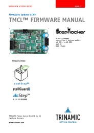
TMCM-1110 stepRocker Hardware Manual (V1.04 / 2011-OCT-31) 8<br />
4.2.1 Power connector<br />
Take care of the polarity, wrong polarity can destroy the board!<br />
Pin Label Direction Description<br />
1 GND Power (GND) Common system supply and signal ground<br />
2 10… 30V Power (input) Power supply voltage.<br />
Table 4.2: Power connector<br />
4.2.2 I/O connector to S3FN41F<br />
Pin Label Direction Description<br />
1 GND Power (GND) Supply and signal ground<br />
2 GND Power (GND) Supply and signal ground<br />
3 PWMD_0 in/out General purpose I/O (+5V compatible)<br />
4 PWMU_0 in/out General purpose I/O (+5V compatible)<br />
5 PWMD_1 in/out General purpose I/O (+5V compatible)<br />
6 PWMU_1 in/out General purpose I/O (+5V compatible)<br />
7 PWMD_2 in/out General purpose I/O (+5V compatible)<br />
8 PWMU_2 in/out General purpose I/O (+5V compatible)<br />
9 AIN_0 in Analog input (can be used as home switch)<br />
input voltage range: 0… +10V,<br />
resolution: 12bit (0… 4095)<br />
10 PHASE_A in General purpose I/O or encoder input channel A (+5V<br />
compatible, internal pull-up to +5V)<br />
11 OpenDrain_1 out Open-drain output (max. 100mA)<br />
12 PHASE_B in General purpose I/O or encoder input channel B (+5V<br />
compatible, internal pull-up to +5V)<br />
13 OpenDrain_2 out Open-drain output (max. 100mA)<br />
14 PHASE_Z in General purpose I/O or encoder input zero channel (+5V<br />
compatible, internal pull-up to +5V)<br />
Table 4.3: I/O connector S3FN41F<br />
I/Os can be used with TMCL forthcoming. Please ask TRINAMIC to meet your needs.<br />
4.2.3 Motor connector<br />
The motor is connected at the motor connector, one phase (phase A) between A1 and A2 and the second phase<br />
(phase B) between B1 and B2.<br />
Do not connect or disconnect the motor while the board is powered as this can destroy the transistors!<br />
Pin Label Direction Description<br />
1 A1 out Pin 1 of motor coil A<br />
2 A2 out Pin 2 of motor coil A<br />
3 B1 out Pin 1 of motor coil B<br />
4 B2 out Pin 2 of motor coil B<br />
Table 4.5: Motor connector<br />
Copyright © 2011, TRINAMIC Motion Control GmbH & Co. KG


