1 - Trinamic
1 - Trinamic
1 - Trinamic

Create successful ePaper yourself
Turn your PDF publications into a flip-book with our unique Google optimized e-Paper software.
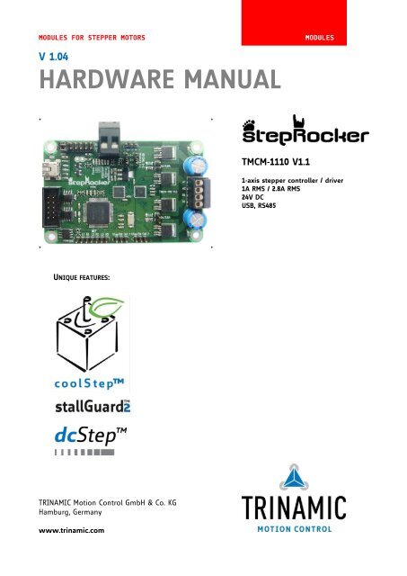
MODULES FOR STEPPER MOTORS MODULES<br />
V 1.04<br />
HARDWARE MANUAL<br />
+ +<br />
+ +<br />
UNIQUE FEATURES:<br />
TRINAMIC Motion Control GmbH & Co. KG<br />
Hamburg, Germany<br />
www.trinamic.com<br />
TMCM-1110 V1.1<br />
1-axis stepper controller / driver<br />
1A RMS / 2.8A RMS<br />
24V DC<br />
USB, RS485
TMCM-1110 stepRocker Hardware Manual (V1.04 / 2011-OCT-31) 2<br />
Table of contents<br />
1 Life support policy ....................................................................................................................................................... 3<br />
2 Features ........................................................................................................................................................................... 4<br />
3 Order codes .................................................................................................................................................................... 5<br />
4 Mechanical and electrical interfacing ..................................................................................................................... 6<br />
4.1 Size of board ......................................................................................................................................................... 6<br />
4.2 Connectors ............................................................................................................................................................. 7<br />
4.2.1 Power connector ............................................................................................................................................ 8<br />
4.2.2 I/O connector to S3FN41F ........................................................................................................................... 8<br />
4.2.3 Motor connector............................................................................................................................................. 8<br />
4.2.4 Reference switch connector to TMC429 .................................................................................................. 9<br />
4.2.5 RS485 and CAN connector .......................................................................................................................... 9<br />
4.2.6 USB connector .............................................................................................................................................. 10<br />
4.2.7 Step/dir input connector (motor 0) ........................................................................................................ 10<br />
4.2.8 Step/dir output connectors (motor 1 and motor 2) .......................................................................... 10<br />
4.2.9 µC programming interface ........................................................................................................................ 11<br />
4.3 Jumper settings .................................................................................................................................................. 12<br />
4.4 LEDs ....................................................................................................................................................................... 13<br />
4.5 Communication .................................................................................................................................................. 13<br />
4.5.1 RS485 ............................................................................................................................................................... 13<br />
4.5.2 USB................................................................................................................................................................... 14<br />
4.5.3 CAN (retro-fit option) .................................................................................................................................. 15<br />
5 Functional description .............................................................................................................................................. 16<br />
5.1 Extensions of the TMCM-1110 stepRocker .................................................................................................. 17<br />
6 Operational ratings .................................................................................................................................................... 18<br />
7 Revision History .......................................................................................................................................................... 19<br />
7.1 Document revision ............................................................................................................................................ 19<br />
7.2 Hardware revision ............................................................................................................................................. 19<br />
8 References..................................................................................................................................................................... 19<br />
Copyright © 2011, TRINAMIC Motion Control GmbH & Co. KG
TMCM-1110 stepRocker Hardware Manual (V1.04 / 2011-OCT-31) 3<br />
1 Life support policy<br />
TRINAMIC Motion Control GmbH & Co. KG does not authorize<br />
or warrant any of its products for use in life support systems,<br />
without the specific written consent of TRINAMIC Motion<br />
Control GmbH & Co. KG.<br />
Life support systems are equipment intended to support or<br />
sustain life, and whose failure to perform, when properly<br />
used in accordance with instructions provided, can be<br />
reasonably expected to result in personal injury or death.<br />
© TRINAMIC Motion Control GmbH & Co. KG 2011<br />
Information given in this data sheet is believed to be accurate<br />
and reliable. However neither responsibility is assumed for<br />
the consequences of its use nor for any infringement of<br />
patents or other rights of third parties, which may result from<br />
its use.<br />
Specifications are subject to change without notice.<br />
Copyright © 2011, TRINAMIC Motion Control GmbH & Co. KG
TMCM-1110 stepRocker Hardware Manual (V1.04 / 2011-OCT-31) 4<br />
2 Features<br />
The TMCM-1110 stepRocker is a single axis motor controller/driver board for 2-phase bipolar stepper motors. It<br />
features the TRINAMIC controller/driver chain consisting of TMC429 and TMC262 in combination with a Samsung<br />
S3FN41F processor. The Module is intended to be a fully functional development platform. A stepRocker can be<br />
extended to a full 3-axes system using two additional boards, because the TMCM-1110 stepRocker board can be<br />
both, master or slave.<br />
Software wise two different approaches are possible: it is possible to use the stepRocker with the<br />
<strong>Trinamic</strong>MotionControlLanguage TMCL. The board comes with the preinstalled firmware. The integrated<br />
development environment TMCL-IDE for PC can be downloaded and used free of charge. It is possible to<br />
remote control the stepRocker or to write and download complete command sequences for standalone use.<br />
The alternative is to write the firmware for the microcontroller using downloadable software tools and motion<br />
control libraries (refer to www.motioncontrol-community.org).<br />
Applications<br />
Highly compact single axis stepper motor controller/driver board for 2-phase bipolar stepper motors<br />
2- and 3-axis systems using additional boards as slaves<br />
Electrical data<br />
Supply voltage: +24V DC (+10… +30V DC)<br />
Motor current: up to 1A RMS or 2.8A RMS (can be selected with jumpers)<br />
Mechanical data<br />
Board size: 85mm x 55mm, height 15mm max. without mating connectors<br />
4 mounting holes for M3 screws<br />
Interfaces<br />
RS485 host interface<br />
USB 2.0 host interface (mini-USB connector)<br />
Step/Dir input (TTL level)<br />
Step/Dir outputs (TTL level) for multi axis applications<br />
3 multi-purpose inputs (can be used for ABN-encoder)<br />
2 limit switch inputs per motor<br />
6 multi-purpose I/Os<br />
2 open-drain outputs<br />
µC programming interface SWD (single wire debug / pads on PCB)<br />
Retro-fit option: CAN 2.0B communication interface<br />
Features<br />
TMC429 stepper motor controller IC for on-the-fly alteration of many motion specific parameters<br />
TMC262 advanced stepper motor driver IC with stallGuard2 and coolStep features. Using the spreadCycle<br />
chopper the µstep current sine wave is well formed with smooth zero crossing.<br />
Ready for dcStep<br />
Up to 256 microsteps per fullstep trough mircoPlyer technology<br />
2 x end switch for all three axes.<br />
EEPROM<br />
Software<br />
TMCL remote (direct mode) and standalone operation (memory for up to 1024 TMCL commands)<br />
Fully supported by TMCL-IDE (PC based integrated development environment)<br />
Please note that the TMCM-1110 stepRocker can be used with a special TMCL firmware version with its source<br />
codes in order to provide new developments, too. Here is your platform for individual TMCL extensions:<br />
www.motioncontrol-community.org or www.steprocker.com.<br />
Copyright © 2011, TRINAMIC Motion Control GmbH & Co. KG
TMCM-1110 stepRocker Hardware Manual (V1.04 / 2011-OCT-31) 5<br />
3 Order codes<br />
The standard version of the stepRocker has RS485 interface and USB interface.<br />
The module is pre-programmed with TRINAMICs TMCL Firmware with all available features. For developing<br />
one’s own firmware please refer to www.steprocker.com or www.motioncontrol-community.org.<br />
Order code Description Size of unit [mm3 ]<br />
TMCM-1110 stepRocker The stepRocker is a 1-axes bipolar stepper motor 85 x 55 x 15<br />
controller/driver module with RS485 and USB<br />
Table 3.1: TMCM-1110 order codes<br />
Order code Description<br />
CABLE-USB-MINI USB-mini cable<br />
Table 3.4: Related product<br />
Copyright © 2011, TRINAMIC Motion Control GmbH & Co. KG
TMCM-1110 stepRocker Hardware Manual (V1.04 / 2011-OCT-31) 6<br />
4 Mechanical and electrical interfacing<br />
4.1 Size of board<br />
The board with the controller/driver electronics has an overall size of 85mm x 55mm x 15mm without mating<br />
connectors. It offers four mounting holes for M3 screws (3.2mm diameter). All four mounting holes are<br />
connected to the ground plane (signal and supply ground) of the module.<br />
55<br />
4<br />
4<br />
Ø 3.2<br />
4 x M3<br />
screws<br />
Copyright © 2011, TRINAMIC Motion Control GmbH & Co. KG<br />
85<br />
Figure 4.1: Board dimensions and position of mounting holes (all values in mm).<br />
4
TMCM-1110 stepRocker Hardware Manual (V1.04 / 2011-OCT-31) 7<br />
4.2 Connectors<br />
The TMCM-1110 stepRocker has nine connectors altogether. There are two screw connectors for power and<br />
motor and two interface connectors (mini-USB and RS485). Further, the stepRocker has one connector for<br />
reference switches for all three motors, the driver input connector (TTL level) for motor 0, two controller output<br />
connectors (TTL level) for motors 1 and 2 and the GPIO connector, which can be used e.g. for connecting an<br />
ABN-encoder.<br />
Start with power supply OFF and do not disconnect the motor while the board is powered as this can<br />
destroy the transistors!<br />
USB<br />
RS485<br />
(CAN<br />
optional)<br />
1<br />
1<br />
GPIO<br />
1<br />
Reference<br />
switches<br />
Power<br />
1<br />
14 1<br />
Driver<br />
In<br />
Controller<br />
Out 1<br />
Controller<br />
Out 2<br />
Figure 4.2: TMCM-1110 stepRocker connectors<br />
Copyright © 2011, TRINAMIC Motion Control GmbH & Co. KG<br />
1<br />
1<br />
CONNECTORS OF TMCM-1110 STEPROCKER<br />
Label Connector type Mating connector type<br />
Power<br />
RIA 220-02, 2 pol., 5.08mm pitch,<br />
shrouded header<br />
RIA 249-02, screw type terminal block,<br />
pluggable, centerline 5.08mm pitch<br />
Motor<br />
RIA 183-04, 4 pol., 3.5mm pitch,<br />
shrouded header<br />
RIA 169-04, screw type terminal block,<br />
pluggable, centerline 3.5mm pitch<br />
USB USB-mini female connector USB-mini male connector<br />
Low profile box header without locking Low profile IDC socket connector, 10pol.,<br />
RS485/CAN<br />
bar, type 8380, 10 pol., DIN 41651,<br />
2.54mm pitch<br />
DIN41651, 2.54mm pitch<br />
GPIO<br />
Multi-pin-connector, 14 pol., 2.54mm<br />
pitch<br />
Female connector with 2.54mm pitch<br />
Ref. switches Multi-pin-connector, 7 pol., 2.54mm pitch Female connector with 2.54mm pitch<br />
Driver In Multi-pin-connector, 3 pol., 2.54mm pitch Female connector with 2.54mm pitch<br />
Controller Out 1, 2 Multi-pin-connector, 3 pol., 2.54mm pitch Female connector with 2.54mm pitch<br />
Table 4.1: Connectors and mating connectors<br />
Because of the characteristic of the TMCM-1110 stepRocker as development platform TRINAMIC offers its<br />
internal circuit diagram here: www.steprocker.com or www.motioncontrol-community.org. Please refer to the<br />
diagram in order to get further information about the pin assignments of µC, TMC429, and TMC262.<br />
1<br />
Motor
TMCM-1110 stepRocker Hardware Manual (V1.04 / 2011-OCT-31) 8<br />
4.2.1 Power connector<br />
Take care of the polarity, wrong polarity can destroy the board!<br />
Pin Label Direction Description<br />
1 GND Power (GND) Common system supply and signal ground<br />
2 10… 30V Power (input) Power supply voltage.<br />
Table 4.2: Power connector<br />
4.2.2 I/O connector to S3FN41F<br />
Pin Label Direction Description<br />
1 GND Power (GND) Supply and signal ground<br />
2 GND Power (GND) Supply and signal ground<br />
3 PWMD_0 in/out General purpose I/O (+5V compatible)<br />
4 PWMU_0 in/out General purpose I/O (+5V compatible)<br />
5 PWMD_1 in/out General purpose I/O (+5V compatible)<br />
6 PWMU_1 in/out General purpose I/O (+5V compatible)<br />
7 PWMD_2 in/out General purpose I/O (+5V compatible)<br />
8 PWMU_2 in/out General purpose I/O (+5V compatible)<br />
9 AIN_0 in Analog input (can be used as home switch)<br />
input voltage range: 0… +10V,<br />
resolution: 12bit (0… 4095)<br />
10 PHASE_A in General purpose I/O or encoder input channel A (+5V<br />
compatible, internal pull-up to +5V)<br />
11 OpenDrain_1 out Open-drain output (max. 100mA)<br />
12 PHASE_B in General purpose I/O or encoder input channel B (+5V<br />
compatible, internal pull-up to +5V)<br />
13 OpenDrain_2 out Open-drain output (max. 100mA)<br />
14 PHASE_Z in General purpose I/O or encoder input zero channel (+5V<br />
compatible, internal pull-up to +5V)<br />
Table 4.3: I/O connector S3FN41F<br />
I/Os can be used with TMCL forthcoming. Please ask TRINAMIC to meet your needs.<br />
4.2.3 Motor connector<br />
The motor is connected at the motor connector, one phase (phase A) between A1 and A2 and the second phase<br />
(phase B) between B1 and B2.<br />
Do not connect or disconnect the motor while the board is powered as this can destroy the transistors!<br />
Pin Label Direction Description<br />
1 A1 out Pin 1 of motor coil A<br />
2 A2 out Pin 2 of motor coil A<br />
3 B1 out Pin 1 of motor coil B<br />
4 B2 out Pin 2 of motor coil B<br />
Table 4.5: Motor connector<br />
Copyright © 2011, TRINAMIC Motion Control GmbH & Co. KG
TMCM-1110 stepRocker Hardware Manual (V1.04 / 2011-OCT-31) 9<br />
4.2.4 Reference switch connector to TMC429<br />
Pin Label Direction Description<br />
1 GND Power (GND) Signal and system ground<br />
2 L1 in Input for left reference/limit switch of motor 0<br />
3 R1 in Input for right reference/limit switch of motor 0<br />
4 L2 in Input for left reference/limit switch of motor 1<br />
5 R2 in Input for right reference/limit switch of motor 1<br />
6 L3 in Input for left reference/limit switch of motor 2<br />
7 R3 in Input for right reference/limit switch of motor 2<br />
Table 4.6: Reference switch connector<br />
4.2.5 RS485 and CAN connector<br />
The standard TMCM-1110 stepRocker uses the RS485 interface pins, only.<br />
Pin Label Direction Description<br />
1<br />
2<br />
3 CAN_L bi-directional Differential CAN bus signal (inverting) - retro-fit option<br />
4 CAN_H bi-directional Differential CAN bus signal (non-inverting) - retro-fit option<br />
5 GND Power (GND) Signal and system ground<br />
6 RS485+ bi-directional Differential RS485 bus signal (non-inverting)<br />
7 RS485- bi-directional Differential RS485 bus signal (inverting)<br />
8<br />
9<br />
10<br />
Table 4.7: RS485/CAN connector<br />
4.2.5.1 Prepare the stepRocker for CAN<br />
CAN transceiver<br />
SN65HVD1050D<br />
Housing: SOIC8<br />
0.1µF capacitor<br />
Housing: 0603<br />
Copyright © 2011, TRINAMIC Motion Control GmbH & Co. KG<br />
The table above shows the pin configuration for CAN,<br />
too. Before starting with CAN it is necessary to solder a<br />
SN65HVD1050D CAN transceiver with housing SOIC8 and<br />
a 0.1µF capacitor with housing 0603 on the TMCM-1110<br />
stepRocker. Now, the stepRocker is ready for using the<br />
CAN interface.<br />
Because of the pin assignment CAN and RS485 can be<br />
used at the same time.<br />
It is not necessary to remove the RS485 transceiver.
TMCM-1110 stepRocker Hardware Manual (V1.04 / 2011-OCT-31) 10<br />
4.2.6 USB connector<br />
Please note, that the USB interface is forthcoming available. Please use the RS485 interface till then.<br />
A USB interface is available via a mini-USB connector. This module supports USB 2.0 Full-Speed (12Mbit/s)<br />
connections.<br />
On-board digital core logic (mainly processor and EEPROM) will be powered via USB in case no other supply is<br />
connected. This can be used to set parameters / download TMCL programs or to perform firmware updates<br />
with the module connected via USB, only.<br />
Pin Label Direction Description<br />
1<br />
VBUS Power<br />
(+5V input)<br />
+5V supply from host<br />
2 D- bi-directional USB Data -<br />
3 D+ bi-directional USB Data +<br />
4 ID Connected to signal and system ground<br />
5 GND Power (GND) Signal and system ground<br />
Table 4.9: USB connector<br />
4.2.7 Step/dir input connector (motor 0)<br />
The TMCM-1110 stepRocker is equipped with a step/dir input connector for motor 0. Via this connector an<br />
external motion controller can be used together with the on-board driver electronics. For selecting an external<br />
motion controller instead of the on-board TMC429 motion controller two jumpers have to be set (please refer<br />
to chapter 4.3).<br />
Pin Label Direction Description<br />
1 GND Power (GND) Signal and System ground<br />
2 Step In in Driver step input signal (+5V compatible)<br />
3 Dir In in Driver direction input signal (+5V compatible)<br />
Table 4.1: Step/dir input connector<br />
4.2.8 Step/dir output connectors (motor 1 and motor 2)<br />
The TMC429 motion controller on the stepRocker is able to control up to three stepper motors. Its Step/Dir<br />
outputs (TTL level) for motor 1 and motor 2 are leaded through to connectors Step/Dir Out 1 and Step/Dir Out 2.<br />
The TMCM-1110 stepRocker can be extended to a complete motion controller/driver system for all three motors.<br />
Pin Label Direction Description<br />
1 GND Power (GND) Signal and System ground<br />
2 Step Out out Driver step output signal (+5V compatible)<br />
3 Dir Out out Driver direction output signal (+5V compatible)<br />
Table 4.2: Step/dir output connectors<br />
Copyright © 2011, TRINAMIC Motion Control GmbH & Co. KG
TMCM-1110 stepRocker Hardware Manual (V1.04 / 2011-OCT-31) 11<br />
4.2.9 µC programming interface<br />
The programming pads of the interface are on the backside of the module. There are possibilities for<br />
programming in two different modes: debug mode and serial writing mode. The selection of the programming<br />
mode depends on the chosen adapter. Further, it is possible to use the programming pads of the µC interface<br />
by soldering adequate contacts directly on the programming pads.<br />
Please refer to the datasheet of the S3FN41F microcontroller for further information.<br />
http://www.samsung.com/global/system/business/semiconductor/product/2011/6/21/024872um_s3fn41f_rev10.pdf<br />
PROGRAMMING PADS<br />
Pin Label Description<br />
1 GND Module and signal ground<br />
2 +5V +5V DC supply<br />
3 nRST Hardware reset input<br />
4 VPP Connected to pin 14 of the processor (MODE0). VPP is used for mode setting<br />
ether to debug mode or to flash serial writing mode.<br />
Mode 1 Mode 0 Mode setting<br />
0 0 User normal/debug mode.<br />
(Used pins: SWDIO and SWDCLK.)<br />
0 1 User flash serial writing mode.<br />
(Used pins: F_SDAT and PHASEA.)<br />
The user program mode for flash memory programming and sector erasing<br />
uses the internal high voltage generator, which is necessary for flash memory<br />
programming and sector erasing. In other words, the flash memory controller<br />
has an internal high voltage pumping circuit. Therefore, high voltage to VPP<br />
pin is not needed. To program the data into the flash ROM or sector erase in<br />
this mode, control registers should be used.<br />
5 PHASEA Function: F_CLK – serial clock.<br />
Write speed: max 250kHz<br />
Read speed: max 3MHz<br />
6 F_SDAT Serial Data pin (output for reading, input for writing)<br />
Input and push-pull output port can be assigned.<br />
7 SWDIO Select/Serial Wire Data I/O. Internal pull-up<br />
8 SWDCLK Serial wire clock<br />
Table 4.3: Programming pads<br />
SWDCLK<br />
SWDIO<br />
F SDAT<br />
PHASEA<br />
Figure 4.2: Programming pads<br />
VPP<br />
nRST<br />
+5V<br />
GND<br />
Copyright © 2011, TRINAMIC Motion Control GmbH & Co. KG<br />
1
TMCM-1110 stepRocker Hardware Manual (V1.04 / 2011-OCT-31) 12<br />
4.3 Jumper settings<br />
The TMCM-1110 stepRocker offers possibilities for settings by jumper. Here, three adjustments are mentioned.<br />
Select motion controller and select motor current are basic. Jumpers on the GPIO connector are optional.<br />
Select<br />
motion<br />
controller<br />
Figure 4.3: Jumper of TMCM-1110 stepRocker<br />
Select<br />
motor<br />
current<br />
Select<br />
motor<br />
current<br />
TMCM-1110 STEPROCKER JUMPERS<br />
Jumper Label Description<br />
Select motor current 1A/2.8A Jumper plugged motor current up to 2.8A RMS<br />
Jumper unplugged motor current up to 1A RMS<br />
Select motion controller 1-2 External<br />
2-3 TMC429<br />
Table 4.4: Jumpers of TMCM-1110 stepRocker<br />
Copyright © 2011, TRINAMIC Motion Control GmbH & Co. KG<br />
Set jumpers to select motion controller TMC429 (on the module)<br />
or external, which have to be connected to Step/dir.<br />
Jumper pins Result<br />
1, 2 External motion controller selected. LEDs<br />
POSCOMP and interrupts are without<br />
statement<br />
2, 3 TMC429 selected
TMCM-1110 stepRocker Hardware Manual (V1.04 / 2011-OCT-31) 13<br />
4.4 LEDs<br />
LEDS OF THE TMCM-1110 STEPROCKER<br />
Status Label Description<br />
Power on POWER This orange LED lights up upon the power supply is working.<br />
LED1<br />
without defined function<br />
LED2<br />
without defined function<br />
Copyright © 2011, TRINAMIC Motion Control GmbH & Co. KG<br />
LED1 This yellow LED is applicable and can be used customer specific.<br />
The LED is connected to pin 59 of the S3FN41F microcontroller.<br />
LED2 This yellow LED is applicable and can be used customer specific.<br />
The LED is connected to pin 58 of the S3FN41F microcontroller.<br />
POSCOMP output used POSCOMP This yellow LED lights up if the POSCOMP output of the TMC429 is<br />
used. POSCMP is available for triggering when moving over a<br />
programmable position.<br />
Interrupt detected Interrupt This orange LED lights up upon interrupts. The LED is connected<br />
to the nIND_SDO_C pin of the TMC429.<br />
stallGuard2 detected stallGuard2 This red LED light up upon stalling conditions. The LED is<br />
connected to the SG_TST pin of the TMC262.<br />
Table 4.5: LEDs<br />
Figure 4.4: LEDs of the stepRocker<br />
4.5 Communication<br />
4.5.1 RS485<br />
For remote control and communication with a host system the TMCM-1110 provides a two wire RS485 bus<br />
interface. For proper operation the following items should be taken into account when setting up an RS485<br />
network:<br />
1. BUS STRUCTURE:<br />
The network topology should follow a bus structure as closely as possible. That is, the connection<br />
between each node and the bus itself should be as short as possible. Basically, it should be short<br />
compared to the length of the bus.
TMCM-1110 stepRocker Hardware Manual (V1.04 / 2011-OCT-31) 14<br />
termination<br />
resistor<br />
(120 Ohm)<br />
c:><br />
Host<br />
Slave Slave Slave<br />
node<br />
1<br />
RS485<br />
Figure 4.5: RS485 bus structure<br />
Copyright © 2011, TRINAMIC Motion Control GmbH & Co. KG<br />
}<br />
node<br />
n - 1<br />
node<br />
n<br />
keep distance as<br />
short as possible<br />
termination<br />
resistor<br />
(120 Ohm)<br />
2. BUS TERMINATION:<br />
Especially for longer busses and/or multiple nodes connected to the bus and/or high communication<br />
speeds, the bus should be properly terminated at both ends. The TMCM-1110 does not integrate any<br />
termination resistor. Therefore, 120 Ohm termination resistors at both ends of the bus have to be<br />
added externally.<br />
3. NUMBER OF NODES:<br />
The RS485 electrical interface standard (EIA-485) allows up to 32 nodes to be connected to a single bus.<br />
The bus transceiver used on the TMCM-1110 units (SN65HVD3082ED) has just 1/8th of the standard bus<br />
load and allows a maximum of 256 units to be connected to a single RS485 bus.<br />
4. NO FLOATING BUS LINES:<br />
Avoid floating bus lines while neither the host/master nor one of the slaves along the bus line is<br />
transmitting data (all bus nodes switched to receive mode). Floating bus lines may lead to<br />
communication errors. In order to ensure valid signals on the bus it is recommended to use a resistor<br />
network connecting both bus lines as well defined logic levels. In contrast to the termination resistors<br />
this network is normally required just once per bus. Certain RS485 interface converters available for PCs<br />
already include these additional resistors (e.g. USB-2-485).<br />
4.5.2 USB<br />
RS485+ / RS485A<br />
RS485- / RS485B<br />
Slave Slave<br />
node<br />
n - 1<br />
node<br />
n<br />
+5V<br />
GND<br />
Figure 4.6: RS485 bus lines with resistor network<br />
pull-up (1k)<br />
pull-down (1k)<br />
termination<br />
resistor<br />
(120 Ohm)<br />
For remote control and communication with a host system the TMCM-1110 stepRocker provides a USB 2.0 fullspeed<br />
(12Mbit/s) interface (mini-USB connector). As soon as a USB-Host is connected the module will accept<br />
commands via USB. The TMCM-1110 support USB self powered operation (when an external power is supplied<br />
via the power supply connector) and USB bus powered operation, also (no external power supply via power<br />
supply connector). During USB bus powered operation, only the core digital circuit parts will be operational.<br />
That is, the microcontroller itself and also the EEPROM. Motor movements will not be possible. This mode has<br />
been implemented in order to enable configuration / parameter setting / read-out, firmware updates etc. by just<br />
connecting a USB cable between the module and a host PC. No additional cabling / external devices as e.g.<br />
power supply etc. are required in that case.
TMCM-1110 stepRocker Hardware Manual (V1.04 / 2011-OCT-31) 15<br />
Please note that the module might draw current from the USB +5V bus supply even in USB self powered<br />
operation depending on the voltage level of this supply.<br />
4.5.3 CAN (retro-fit option)<br />
For remote control and communication with a host system the TMCM-1110 stepRocker can be equipped with a<br />
CAN bus interface. Please note, that it is necessary to prepare the board with a CAN transceiver and the<br />
according capacitor first (chapter 4.2.5.1).<br />
For proper operation the following items should be taken into account when setting up a CAN network:<br />
1. BUS STRUCTURE:<br />
The network topology should follow a bus structure as closely as possible. That is, the connection<br />
between each node and the bus itself should be as short as possible. Basically, it should be short<br />
compared to the length of the bus.<br />
termination<br />
resistor<br />
(120 Ohm)<br />
c:><br />
Host<br />
Figure 4.7: CAN bus structure<br />
Slave Slave Slave<br />
node<br />
1<br />
CAN<br />
Copyright © 2011, TRINAMIC Motion Control GmbH & Co. KG<br />
}<br />
node<br />
n - 1<br />
node<br />
n<br />
keep distance as<br />
short as possible<br />
termination<br />
resistor<br />
(120 Ohm)<br />
2. BUS TERMINATION:<br />
Especially for longer busses and/or multiple nodes connected to the bus and/or high communication<br />
speeds, the bus should be properly terminated at both ends. The TMCM-1110 does not integrate any<br />
termination resistor. Therefore, 120 Ohm termination resistors at both ends of the bus have to be<br />
added externally.
TMCM-1110 stepRocker Hardware Manual (V1.04 / 2011-OCT-31) 16<br />
5 Functional description<br />
The TMCM-1110 stepRocker is a highly integrated 1-axes controller/driver module. The TMCM-1110 can be<br />
controlled via RS485 or USB serial interfaces (CAN retro-fit option).<br />
The TMCM-1110 comes with the PC based software development environment TMCL-IDE for the <strong>Trinamic</strong> Motion<br />
Control Language (TMCL). Using predefined TMCL high level commands like move to position a rapid and<br />
fast development of motion control applications is guaranteed. Whereas the boot loader is installed during<br />
production and testing at TRINAMIC and remains normally untouched throughout the whole lifetime, the<br />
firmware can be updated by the user.<br />
Communication traffic is kept low since all time critical operations, e.g. ramp calculation, are performed on<br />
board. Full remote control of device with feedback is possible. The firmware of the module can be updated via<br />
any of the serial interfaces.<br />
In case, you prefer developing your own TMCL commands for the stepRocker refer to www.steprocker.com.<br />
The TMCL boot loader on the board can be used for downloading new TMCL programs including such<br />
personal extensions, too.<br />
The TMCM-1110 module contains the following main components:<br />
˗ ARM Cortex-MO processor Core S3FN41F microcontroller with built-in up to 256 Kbytes program flash<br />
memory and up to 32 Kbytes SRAM. Processor is equipped with crystal (more precision for USB<br />
communication).<br />
˗ TMC429 highly integrated 3 axes stepper motor controller. Step-/direction outputs for motor 0 connected<br />
to TMC262.<br />
˗ TMC262 advanced stepper motor driver IC with stallGuard2 and coolStep with integrated MOSFET<br />
driver transistors (4x power MOSFETs for 2-phase bipolar stepper option) for motor 0.<br />
˗ RS485 and USB transceivers.<br />
˗ On-board switching and linear voltage regulators for supply of on-board digital circuits<br />
RS485<br />
CAN<br />
assembly<br />
option<br />
USB<br />
Inputs<br />
1x analogue<br />
3x with pull-ups<br />
GPIOs<br />
10… 30V DC<br />
4<br />
6<br />
EEPROM<br />
SPI<br />
µC<br />
S3FN41F<br />
progammable<br />
Motion<br />
Controller<br />
TMC429<br />
Figure 5.1: TMCM-1110 stepRocker block diagram<br />
Copyright © 2011, TRINAMIC Motion Control GmbH & Co. KG<br />
SPI<br />
SPI<br />
Step/Dir<br />
IN 0 (Slave)<br />
Step/Dir<br />
Power<br />
Driver<br />
TMC262<br />
Step/Dir<br />
Step/Dir<br />
+5V<br />
+5V<br />
1A RMS/<br />
2.8A RMS<br />
MOSFET<br />
Driver Stage<br />
4 x Mosfet<br />
3x 2 reference<br />
switches<br />
Motor 0<br />
Step/Dir<br />
OUT 1 (Master)<br />
Step/Dir<br />
OUT 2 (Master)
TMCM-1110 stepRocker Hardware Manual (V1.04 / 2011-OCT-31) 17<br />
5.1 Extensions of the TMCM-1110 stepRocker<br />
The TMCM-1110 stepRocker provides the possibility for extension to full 3-axis systems. The stepRocker itself can<br />
be used as master or slave. An example for extensions is shown below.<br />
USB<br />
TMCL<br />
USB / RS485<br />
only initialization<br />
and<br />
parameterization<br />
USB / RS485<br />
only initialization<br />
and<br />
parameterization<br />
GPI /O<br />
3 x REF-IN<br />
Master / Motor 0<br />
S/D OUT<br />
S/D IN<br />
Motor 1<br />
S/D IN<br />
Motor 2<br />
Figure 5.2: TMCM-1110 stepRocker extension<br />
Copyright © 2011, TRINAMIC Motion Control GmbH & Co. KG
TMCM-1110 stepRocker Hardware Manual (V1.04 / 2011-OCT-31) 18<br />
6 Operational ratings<br />
The operational ratings show the intended or the characteristic ranges and should be used as design values.<br />
In no case shall the maximum values be exceeded.<br />
Symbol Parameter Min Typ Max Unit<br />
V Power Power supply voltage 10 12… 24 30 V<br />
V USB Power supply via USB connector 5 V<br />
I USB<br />
I COIL<br />
Current withdrawn from USB supply when<br />
USB bus powered (no other supply connected)<br />
Motor coil current for sine wave peak<br />
(chopper regulated, adjustable via software)<br />
Copyright © 2011, TRINAMIC Motion Control GmbH & Co. KG<br />
85 mA<br />
0 1500 or<br />
I MC Continuous motor current (RMS) 0 1000 or<br />
T ENV<br />
Environment temperature at rated current (no<br />
forced cooling required)<br />
Table 6.1: General operational ratings of the module<br />
4000<br />
2800<br />
mA<br />
mA<br />
-25 tbd 80 °C<br />
Symbol Parameter Min Typ Max Unit<br />
N RS485<br />
Number of nodes connected to<br />
single RS485 network<br />
Table 6.2: Operational ratings of RS485 interface<br />
256
TMCM-1110 stepRocker Hardware Manual (V1.04 / 2011-OCT-31) 19<br />
7 Revision History<br />
7.1 Document revision<br />
Version Date<br />
Author<br />
SD – Sonja Dwersteg<br />
GG – Guido Gandolfo<br />
Description<br />
1.00 2011-OCT-01 SD First version<br />
1.01 2011-OCT-04 GG Minor changes<br />
1.02 2011-OCT-05 SD Minor changes<br />
1.03 2011-OCT-27 SD Minor changes<br />
1.04 2011-OCT-31 SD Minor changes<br />
Figure 7.1: Document revision<br />
7.2 Hardware revision<br />
Version Date Description<br />
TMCM-1110 V1.1 2011-SEP-02 Minor changes from version 1.0 to version 1.1<br />
Figure 7.2: Hardware revision<br />
8 References<br />
[USB-2-485] USB-2-485 interface converter<br />
manual available on http://www.trinamic.com<br />
[TMC262] TMC262 datasheet<br />
manual available on http://www.trinamic.com.<br />
[TMC429] TMC429 datasheet<br />
manual available on http://www.trinamic.com.<br />
[S3FN41F] S3FN41F processor<br />
manual available on www.samsung.com<br />
Copyright © 2011, TRINAMIC Motion Control GmbH & Co. KG