TMC429+TMC26x-EVAL Manual - Trinamic
TMC429+TMC26x-EVAL Manual - Trinamic
TMC429+TMC26x-EVAL Manual - Trinamic

Create successful ePaper yourself
Turn your PDF publications into a flip-book with our unique Google optimized e-Paper software.
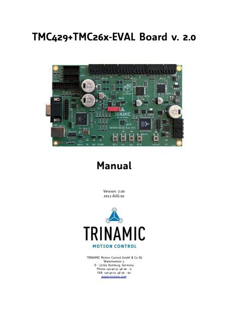
<strong>TMC429+TMC26x</strong>-<strong>EVAL</strong> Board v. 2.0<br />
<strong>Manual</strong><br />
Version: 2.00<br />
2011-AUG-02<br />
TRINAMIC Motion Control GmbH & Co KG<br />
Waterloohain 5<br />
D - 22769 Hamburg, Germany<br />
Phone +49-40-51 48 06 - 0<br />
FAX: +49-40-51 48 06 - 60<br />
www.trinamic.com
<strong>TMC429+TMC26x</strong>-<strong>EVAL</strong> Board V2.0 / <strong>Manual</strong> (V2.00 / 2011-AUG-02) 2<br />
Table of Contents<br />
1 Life support policy ............................................................................................................................ 3<br />
2 Features ............................................................................................................................................ 4<br />
3 Mechanical and electrical interfacing ................................................................................................ 5<br />
3.1 <strong>TMC429+TMC26x</strong>-<strong>EVAL</strong> Board dimensions ................................................................................... 5<br />
4 Connectors & Keys ............................................................................................................................ 6<br />
4.1.1 Power connectors ................................................................................................................. 8<br />
4.1.2 RS232 Serial communication connector ................................................................................ 9<br />
4.1.3 USB connector (USB-B) .......................................................................................................... 9<br />
4.1.4 Motor connectors ................................................................................................................ 10<br />
4.1.5 Encoder connectors ............................................................................................................. 10<br />
4.1.6 Step-Direction (StpDirS) jumpers / connectors (on-board) .................................................. 10<br />
4.1.7 SPI Extender (ExtSPI) .......................................................................................................... 11<br />
4.1.8 Reference Switch connector (RefSw)................................................................................... 11<br />
4.1.9 Analog and Digital Inputs and Outputs (ADIO) .................................................................. 12<br />
5 Operational ratings ......................................................................................................................... 12<br />
6 Functional description ..................................................................................................................... 14<br />
6.1 System architecture .................................................................................................................. 14<br />
6.1.1 Microcontroller .................................................................................................................... 14<br />
7 Getting Started – How to run a Motor ............................................................................................ 15<br />
7.1 Stand-Alone Operation ............................................................................................................. 15<br />
7.2 Evaluation Software Operation ................................................................................................ 15<br />
8 Evaluation Software ........................................................................................................................ 16<br />
8.1 Interface ................................................................................................................................... 17<br />
8.1.1 Installing Virtual COM port for USB .................................................................................... 17<br />
8.1.2 Physical RS232 .................................................................................................................... 19<br />
8.2 Start Window ........................................................................................................................... 19<br />
8.3 Advanced ................................................................................................................................. 21<br />
9 TMCL ............................................................................................................................................ 35<br />
9.1 Communicating with PC .......................................................................................................... 35<br />
9.1.1 Binary command format ..................................................................................................... 35<br />
9.1.2 Reply format ....................................................................................................................... 36<br />
9.1.3 Direct Register Access ......................................................................................................... 36<br />
10 Revision history .............................................................................................................................. 37<br />
10.1 Document revision ................................................................................................................... 37<br />
10.2 Hardware revision .................................................................................................................... 37<br />
10.3 Firmware revision .................................................................................................................... 38<br />
10.4 Software revision (PC Application Software Revision) ............................................................. 39<br />
11 References ....................................................................................................................................... 39<br />
Copyright © 2011, TRINAMIC Motion Control GmbH & Co. KG
<strong>TMC429+TMC26x</strong>-<strong>EVAL</strong> Board V2.0 / <strong>Manual</strong> (V2.00 / 2011-AUG-02) 3<br />
1 Life support policy<br />
TRINAMIC Motion Control GmbH & Co. KG does not authorize<br />
or warrant any of its products for use in life support systems,<br />
without the specific written consent of TRINAMIC Motion<br />
Control GmbH & Co. KG.<br />
Life support systems are equipment intended to support or<br />
sustain life, and whose failure to perform, when properly<br />
used in accordance with instructions provided, can be<br />
reasonably expected to result in personal injury or death.<br />
© TRINAMIC Motion Control GmbH & Co. KG 2011<br />
Information given in this data sheet is believed to be accurate<br />
and reliable. However neither responsibility is assumed for<br />
the consequences of its use nor for any infringement of<br />
patents or other rights of third parties, which may result from<br />
its use.<br />
Specifications are subject to change without notice<br />
Copyright © 2011, TRINAMIC Motion Control GmbH & Co. KG
<strong>TMC429+TMC26x</strong>-<strong>EVAL</strong> Board V2.0 / <strong>Manual</strong> (V2.00 / 2011-AUG-02) 4<br />
2 Features<br />
This evaluation board is for evaluation of the motion controller TMC429, for the stepper motor drivers<br />
TMC262, TMC261, TMC260, and for the incremental encoder interface chip TMC424.<br />
Applications<br />
motion control application without encoder<br />
motion control applications with encoder<br />
Electrical data<br />
Supply voltage: common supply voltages +12VDC / +24VDC / +48VDC (TMC261 only)<br />
Programmable Motor current up to 3.0A RMS resp. 1.4 RMS (M1 : 4.3A peak, M2 : 2A peak, M3 : 2A peak)<br />
Integrated encoder interface (TMC424)<br />
Integrated interfaces for three incremental encoders (ABN)<br />
Integrated bipolar stepper motor drivers (based on TMC262, TMC261, TMC260)<br />
Up to 256 micro steps per full step<br />
Dynamic current control<br />
Integrated protection<br />
High precision sensorless motor load measurement stallGuard2<br />
Automatic load dependent motor current adaptation for reduced power consumption and heat<br />
dissipation (coolStep)<br />
Interfaces<br />
USB (USB-B), RS232<br />
Step/direction<br />
SPI<br />
reference switch inputs<br />
ABN encoder inputs<br />
Software<br />
TMCL & PC-Software<br />
stand-alone operation or remote controlled operation<br />
program memory (non volatile) for up to 2048 TMCL commands<br />
PC-based application development software TMCL-IDE available for free<br />
PC-based stand-alone evaluation software available for free<br />
Please refer to separate TMCL Firmware <strong>Manual</strong>.<br />
Copyright © 2011, TRINAMIC Motion Control GmbH & Co. KG
<strong>TMC429+TMC26x</strong>-<strong>EVAL</strong> Board V2.0 / <strong>Manual</strong> (V2.00 / 2011-AUG-02) 5<br />
3 Mechanical and electrical interfacing<br />
3.1 <strong>TMC429+TMC26x</strong>-<strong>EVAL</strong> Board dimensions<br />
Figure 3.1 Dimensions of <strong>TMC429+TMC26x</strong> Evaluation Board<br />
Copyright © 2011, TRINAMIC Motion Control GmbH & Co. KG
<strong>TMC429+TMC26x</strong>-<strong>EVAL</strong> Board V2.0 / <strong>Manual</strong> (V2.00 / 2011-AUG-02) 6<br />
4 Connectors & Keys<br />
The TMC429 evaluation board v.1.1 is for evaluation of the TMC429 motion controller, the stepper motor<br />
drivers TMC260 and TMC261, and TMC424 triple encoder interface. The board offers 3 connectors for up to<br />
three stepper motors, three connectors for up to three incremental encoders (ABN), USB-B, RS232, power<br />
supply connectors. Additionally, the board is equipped with reference switch inputs, analog and digital<br />
general purpose IOs to interface external components as electric brake or torque sensor. An additional<br />
analog provides a direct interface to a multi-meter. Dedicated outputs of the TMC429 (nINT and POSCMP) are<br />
directly available via jumper connectors. Internal SPI signals resp. Step-Direction signals between TMC429<br />
and the stepper motor drivers TMC260 / TMC261 are available at a jumper field. With this, one can feed<br />
these signals to external drivers or can can uses externally generated signals. So, with this one can evaluate<br />
the the TMC429 and the stepper motor drivers TMC260 / TMC261 separately.<br />
The board is equipped with some keys for stand-alone operation. The left and right key turns the stepper<br />
motor number one left (negative direction) or right (positive). Two reference switches can be simulated via<br />
REFL1 (left reference switch of motor 1) and REFR1 (right reference switch of motor 1). The switch coolStep<br />
switches the coolStep function on/off. LEDs on the board indicate that the board is powered and if<br />
coolStep is switched on of off.<br />
Figure 4.1 Connectors of <strong>TMC429+TMC26x</strong> Evaluation Board<br />
Key Label Description<br />
S401 REFL1 left reference switch for stepper motor number one<br />
S403 left move left, move into negative direction, cw/ccw depends on motor<br />
S404 right move right, move into positive direction, cw/ccw depends on motor<br />
S402 REFR1 right reference switch for stepper motor number one<br />
S405 coolStep switch on/off the coolStep function<br />
Table 4.1: Key overview<br />
Copyright © 2011, TRINAMIC Motion Control GmbH & Co. KG
<strong>TMC429+TMC26x</strong>-<strong>EVAL</strong> Board V2.0 / <strong>Manual</strong> (V2.00 / 2011-AUG-02) 7<br />
Connector Label Description<br />
X107 Power40V standard power supply 12V … 40V for the TMC262, TMC260, and TMC261<br />
X101 Power48V additional power supply for up to 48V for the TMC261<br />
X403 StpDirS step and direction signals between TMC429 and TMC26x drivers<br />
X306 Encoder1 ABN encoder inputs for motor #1<br />
X502 Motor1 stepper motor #1<br />
X302 Encoder2 ABN encoder inputs for motor #2<br />
X604 Motor2 stepper motor #2<br />
X303 Encoder3 ABN encoder inputs for motor #3<br />
X702 Motor3 stepper motor 3<br />
J203 Monitor output for analog meter (MTR) for visualization of stallGuard and coolStep<br />
J402 nINT low active interrupt output of the TMC429<br />
J403 POSCMP POSCMP output of the TMC429<br />
J208 USB-B USB-B connector at the board for USB-A connector cable to PC<br />
J201 RS232 RS232 connector to PC with +/-12V level<br />
X202 DEBUG RxD and TxD with 3.3V logic level (UART)<br />
J204 JTAG JTAG programming adapter for the ARM micro controller<br />
J207 RESET Reset of the ARM micro controller to disable it for external control via ExtSPI<br />
X801 ExtSPI external SPI connector for customer to control drivers by external SPI signals<br />
J202 ADIO general purpose analog and digital IOs<br />
J404 RefSw reference switch inputs for the TMC429<br />
J502 SG1 stallGuard output of motor driver 1 and ground pin<br />
J602 SG2 stallGuard output of motor driver 2 and ground pin<br />
J701 SG3 stallGuard output of motor driver 3 and ground pin<br />
Table 4.2: Connector overview<br />
The naming scheme of the connectors is associated with the pages of the schematic – for example X107<br />
(Power40V) is on page 1 of the schematic, X306 is on page 3 of the schematic.<br />
Connector<br />
Type<br />
Copyright © 2011, TRINAMIC Motion Control GmbH & Co. KG<br />
Vendor, WWW, Type, Order Number<br />
Power Phoenix Contact, http://www.phoenixcontact.com/, MSTB 2,5/ 2-ST-5,08, 2 way<br />
Motor RIA-CON, http://www.ria-connect.net/en/home, Type 169 (small), 4 way, 311 691 04<br />
Encoder RIA-CON, http://www.ria-connect.net/en/home, Type 169 (small), 5 way, 311 691 05<br />
Table 4.3: Connector types
<strong>TMC429+TMC26x</strong>-<strong>EVAL</strong> Board V2.0 / <strong>Manual</strong> (V2.00 / 2011-AUG-02) 8<br />
4.1.1 Power connectors<br />
The evaluation board hast two separate power supply connectors due to different stepper motor driver<br />
supply voltages (TMC260 and TMC262 vs. and TMC261). Internally, the Power48V is connected via a diode<br />
from the Power40V. So, for any power supply within range of 12V … 40V a single voltage power supply is<br />
sufficient for the board.<br />
When using supply voltages near the upper limit, a regulated power supply is mandatory. Please ensure<br />
that enough power filtering capacitors are available in the system (2200µF or more recommended) in order<br />
to absorb mechanical energy fed back by the motor in stalling conditions. In larger systems a suppressor<br />
diode circuitry might be required in order to limit the maximum voltage when the motor is operated at high<br />
velocities.<br />
The power supply should be able to supply the nominal motor voltage at the desired maximum motor<br />
power. In no case shall the supply value exceed the upper voltage limit.<br />
To ensure reliable operation of the unit, the power supply has to have a sufficient output capacitor and the<br />
supply cables should have a low resistance, so that the chopper operation does not lead to an increased<br />
power supply ripple directly at the unit. Power supply ripple due to the chopper operation should be kept at<br />
a maximum of a few 100mV.<br />
Guidelines for power supply:<br />
a) keep power supply cables as short as possible<br />
b) use large diameters for power supply cables<br />
c) add 2200µF or larger filter capacitors near the motor driver unit especially if the distance to the<br />
power supply is large (i.e. more than 2-3m)<br />
Table 4.4: Connector Power40V<br />
2<br />
1<br />
Pin Label Description<br />
1 GND power ground<br />
2 +12V … +40V power supply up to 40V<br />
When the higher voltage power supply is used, the 40V needs to be powered too.<br />
2<br />
1<br />
Pin Label Description<br />
1 GND power ground<br />
2 +12V … +48V power supply up to 48V<br />
Table 4.5: Connector (additional) Power48V for TMC261<br />
Copyright © 2011, TRINAMIC Motion Control GmbH & Co. KG
<strong>TMC429+TMC26x</strong>-<strong>EVAL</strong> Board V2.0 / <strong>Manual</strong> (V2.00 / 2011-AUG-02) 9<br />
Figure 4.2: Power connectors scheme (Power40V & Power48V)<br />
4.1.2 RS232 Serial communication connector<br />
The module supports RS232 and USB communication over this connector. For communication via RS232 a<br />
cable with metal connectors is required. The board is equipped with a male RS232 connector. For RS232<br />
connection with a PC an extension cable is required (cable with one side female connector and the other<br />
side with a male connector with pins 2, 3, 5 connected).<br />
1 -<br />
2 TxD<br />
3 RxD<br />
4 -<br />
5 -<br />
signal ground, not connected on PCB, fixed<br />
by a hookup-wire (for plastic "shield" cables)<br />
6 -<br />
7 -<br />
8 -<br />
9 -<br />
10, 11 GND ground, shield<br />
Table 4.6: Connector for serial communication<br />
4.1.3 USB connector (USB-B)<br />
A 4-pin standard USB-B connector is available on board.<br />
Pin Label Description<br />
1 VBUS +5V power<br />
2 D- Data –<br />
3 D+ Data +<br />
4 GND Ground<br />
Table 4.7: USB-B connector<br />
Pin Label Description<br />
Copyright © 2011, TRINAMIC Motion Control GmbH & Co. KG
<strong>TMC429+TMC26x</strong>-<strong>EVAL</strong> Board V2.0 / <strong>Manual</strong> (V2.00 / 2011-AUG-02) 10<br />
4.1.4 Motor connectors<br />
4<br />
1<br />
Pin Label Description<br />
1 OA1 Motor coil A<br />
2 OA2 Motor coil A<br />
3 OB1 Motor coil B<br />
4 OB2 Motor coil B<br />
Table 4.8: Connector for step/direction signals<br />
4.1.5 Encoder connectors<br />
5<br />
1<br />
Pin Label Description<br />
1 +5V +5V supply for encoder<br />
2 A A input (with pull-up R on board)<br />
3 B B input (with pull-up R on board)<br />
4 N N input (with pull-up R on board)<br />
5 GND ground<br />
Table 4.9: Connector for ABN incremental encoder<br />
4.1.6 Step-Direction (StpDirS) jumpers / connectors (on-board)<br />
Pin Label Description<br />
1 nSCS3_D3 TMC429 DIR output D3 (square Pad)<br />
2 DIR_3 TMC26x DIR_3 input<br />
3 nSCS2_S3 TMC429 step output S3<br />
11<br />
1 4 STEP_3 TMC26x STEP_3 input<br />
5 nSCS_S_S2 TMC429 step output S2<br />
6 STEP_2 TMC26x STEP_2 input<br />
12<br />
2 7 SDI_S_D2 TMC429 DIR output D2<br />
8 DIR_2 TMC26x DIR_2 input<br />
9 SDO_S_S1 TMC429 step output S1<br />
10 STEP_1 TMC26x STEP_1 input<br />
11 SCK_S_D1 TMC429 DIR output D1<br />
12 DIR_1 TMC26x DIR_1 input<br />
Table 4.10: Step-Direction jumper / connector<br />
For stand-alone operation of the board with TMC429 with step/direction mode, the jumper pins need to be<br />
connected as by six jumpers (1-2, 3-4, 5-6, 7-8, 9-10, 11-12). Please refer Figure 4.3.<br />
For external step/direction control of the drivers, the jumpers have to be disconnected and the even<br />
numbered pins (2, 4, ...) can be used as connectors.<br />
Pin 1 is identified by a square pad at the bottom side (soldering side) of the board - the other pads are<br />
circular.<br />
11<br />
12<br />
1<br />
2<br />
Figure 4.3: StpDirS on-board connection scheme for stand-alone operation<br />
Copyright © 2011, TRINAMIC Motion Control GmbH & Co. KG
<strong>TMC429+TMC26x</strong>-<strong>EVAL</strong> Board V2.0 / <strong>Manual</strong> (V2.00 / 2011-AUG-02) 11<br />
4.1.7 SPI Extender (ExtSPI)<br />
The SPI external connector can be used to drive the TMC26x drivers without the TMC429.<br />
2<br />
1<br />
Table 4.11: SPI extender / connetor<br />
20<br />
19<br />
4.1.8 Reference Switch connector (RefSw)<br />
Pin Label Description<br />
1 +5V +5V supply voltage<br />
2 10 2<br />
3<br />
GND<br />
REF1<br />
ground<br />
reference switch input REF1 of TMC429<br />
4 REFR1 reference switch input REFR1 of TMC429<br />
5 REF2 reference switch input REF2 of TMC429<br />
1 9 6 REFR2 reference switch input REFR2 of TMC429<br />
7 REF3 reference switch input REF3 of TMC429<br />
8 REFR3 reference switch input REFR3 of TMC429<br />
9 GND ground<br />
10 +3.3V +3.3V supply voltage<br />
Table 4.12: Step-Direction jumper / connector<br />
Copyright © 2011, TRINAMIC Motion Control GmbH & Co. KG<br />
Pin Label Description<br />
1 MISO Master In Slave Out<br />
2 +3.3V +3.3V voltage supply<br />
3 SCK SPI clock<br />
4 MOSI Mater Out Slave In<br />
5 GND ground<br />
6 GND ground<br />
7 nSC_429 nSCS_C signal of the TMC429<br />
8 CLK_429 CLK feed to TMC429 via multiplexer<br />
9 nCS_DRV1 CSN of driver 1<br />
10 SPI_SEL SPI selection signal<br />
11 nCS_DRV2 CSN of driver 2<br />
12 CS_SEL chip select signal (pls. refer schematic)<br />
13 nCS_DRV3 CSN of driver 3<br />
14 CLK_DRV clock for the stepper motor drivers<br />
15 nCS_CON not Chip Select CONector<br />
16 GND ground<br />
17 nCS_424 nCS of TMC424<br />
18 GND ground<br />
19 nRES_424 reset signal for the TMC424<br />
20 CLK_424 clock for the TMC424
<strong>TMC429+TMC26x</strong>-<strong>EVAL</strong> Board V2.0 / <strong>Manual</strong> (V2.00 / 2011-AUG-02) 12<br />
4.1.9 Analog and Digital Inputs and Outputs (ADIO)<br />
These IOs might be renamed later when the firmware of the TMC429 evaluation board will process these<br />
with dedicated functions.<br />
Pin Label Description<br />
1 A0 analog input of µC (A0)<br />
2 10 2<br />
3<br />
GND<br />
+5V<br />
ground<br />
+5V supply voltage<br />
4 A3 analog input of µC (A3)<br />
5 PWM1 analog output via PWM on PWM1 of µC<br />
1 9 6 A2 analog input of µC (A2)<br />
7 PB24 digital IO of µC<br />
8 A1 analog input of µC (A1)<br />
9 PB25 digital IO of µC (PB25)<br />
10 +3.3V +3.3V supply voltage<br />
Table 4.13: Analog and Digital Inputs and Outputs (ADIO)<br />
5 Operational ratings<br />
The operational ratings shown below should be used as design values. In no case should the maximum<br />
values been exceeded during operation.<br />
The maximum power supply current need depends on the used motors and the supply voltage.<br />
Symbol Parameter Min Typ Max Unit<br />
V12V40 Power supply voltage for operation 12 12, 24 40 V<br />
V12V48 Power supply voltage for operation 12 12, 24, 48 48 V<br />
I COIL_RMS_tmc262 Continuous motor 1 current (RMS) 0.10 3.02 A<br />
I COIL_RMS_tmc261 Continuous motor 2 current (RMS) 0.05 1.37 A<br />
I COIL_RMS_tmc260 Continuous motor 3 current (RMS) 0.05 1.37 A<br />
I SUPPLY Power supply current 0.05 6 A<br />
T ENV<br />
Environment temperature at rated<br />
current (no forced cooling required)<br />
Table 5.1: General operational ratings of the module<br />
Copyright © 2011, TRINAMIC Motion Control GmbH & Co. KG<br />
tbd °C
<strong>TMC429+TMC26x</strong>-<strong>EVAL</strong> Board V2.0 / <strong>Manual</strong> (V2.00 / 2011-AUG-02) 13<br />
Symbol Parameter Min Type Max Unit<br />
V REFSWT Input voltage for reference switches 0 5 V<br />
V ABN_INPUTS ABN incremental encoder inputs 0 5 V<br />
V ABN_SUPPLY supply voltage for ABN encoders 5 V<br />
I ABN_SUPPLY supply current for ABN encoders 3 * 100 mA<br />
Table 5.2: Operational ratings of IO signals<br />
Copyright © 2011, TRINAMIC Motion Control GmbH & Co. KG
<strong>TMC429+TMC26x</strong>-<strong>EVAL</strong> Board V2.0 / <strong>Manual</strong> (V2.00 / 2011-AUG-02) 14<br />
6 Functional description<br />
In Figure 6.1 the main parts of the TMC429 evaluation board are shown. The evaluation board is equipped<br />
with a µC with an additional flash memory for later functions, TMC429 motion motion controller, TMC424<br />
encoder interface, and stepper motor drivers. The TMC262 and TMC260 stepper motor driver are for up to<br />
40V supply voltage, the TMC261 stepper motor driver is for up to 48V supply voltage.<br />
RS232<br />
USB<br />
IOs<br />
Flash<br />
Memory<br />
µC<br />
RefSw<br />
Step<br />
Motor<br />
Power<br />
Energy<br />
Efficient Driver<br />
Driver TMC26x<br />
with<br />
TMC262<br />
coolStep<br />
Copyright © 2011, TRINAMIC Motion Control GmbH & Co. KG<br />
ABN-Encoder ABN-Encoder ABN-Encoder<br />
Motion<br />
Controller<br />
TMC429<br />
Step<br />
Motor<br />
Power<br />
Energy<br />
Efficient Driver<br />
Driver TMC26x<br />
with<br />
TMC262<br />
coolStep<br />
Step<br />
Motor<br />
Power<br />
Energy<br />
Efficient Driver<br />
Driver TMC26x<br />
with<br />
TMC262<br />
coolStep<br />
<strong>TMC429+TMC26x</strong> Eval Board V.1.1<br />
Figure 6.1: Functional block diagram of the TMC429 Evaluation Board V.1.1<br />
6.1 System architecture<br />
ABN<br />
ABN<br />
ABN<br />
Encoder<br />
Interface<br />
TMC424<br />
The evaluation board supports the TMCL (TRINAMIC Motion Control Language) and a stand-alone version<br />
for direct register access.<br />
6.1.1 Microcontroller<br />
On the evaluation board the Atmel AT91SAM7X256 is used to run the TMCL firmware and for the<br />
evaluation software. The CPU has 256KB flash memory and a 64KB RAM. The microcontroller runs the TMCL<br />
(TRINAMIC Motion Control Language) operating system which makes it possible to execute TMCL<br />
commands that are sent to the module from the host via the RS232 or USB.<br />
The flash ROM of the microcontroller holds the TMCL operating system and firmware for direct register<br />
access to TMC429 / TMC260 / TMC261. The TMCL operating system can be updated via RS232 or USB. Use<br />
the TMCL-IDE to do this.
<strong>TMC429+TMC26x</strong>-<strong>EVAL</strong> Board V2.0 / <strong>Manual</strong> (V2.00 / 2011-AUG-02) 15<br />
7 Getting Started – How to run a Motor<br />
Important Hint: Never connect or disconnect a motor while it is powered or turning. Connecting or<br />
disconnecting a motor while current flowing through a coil of the motor might damage the motor driver<br />
due to inductive high-voltage – no matter if the motor is at reset or turning. Turning a motor induces a<br />
voltage called Back-EMF (back electromagnetic force). Turning a motor externally (e.g. by a spring or flywheel<br />
mass) drives currents through the coils of the motor and this causes inductive high-voltage while<br />
connecting or disconnecting that might damage a motor driver.<br />
7.1 Stand-Alone Operation<br />
To run a stepper motor, connect a stepper motor to connector M1. Then connect the power supply to<br />
connector Power40V with a supply voltage in range 12V to 40V. Then push and hold key left or push key<br />
right on the evaluation board to accelerate or decelerate the motor.<br />
For the evaluation board, the motor currents are initialized for motor #1 with 0,856A (RMS) and for motor #2<br />
and motor #3 for 0,388A (RMS).<br />
Hint: The six StpDir jumpers need to be set (pls. refer Figure 4.3, page 10).<br />
7.2 Evaluation Software Operation<br />
To run a stepper motor, connect a stepper motor to connector M1. Then connect the power supply to<br />
connector Power40V with a supply voltage in range 12V to 40V.<br />
Then connect either the RS232 or the USB from PC to computer. If you connect the USB first time, you will<br />
be asked for the virtual com port configuration file that is required for configuration of a virtual com port.<br />
For Windows 2000 Systems use the INF file <strong>TMC429+TMC26x</strong>-<strong>EVAL</strong>_32bit_only.inf configuration file. For newer<br />
Windows systems use the <strong>TMC429+TMC26x</strong>-<strong>EVAL</strong>.inf configuration file.<br />
Then start the <strong>TMC429+TMC26x</strong>-<strong>EVAL</strong>.exe software and follow section 8 Evaluation Software, page 16.<br />
Copyright © 2011, TRINAMIC Motion Control GmbH & Co. KG
<strong>TMC429+TMC26x</strong>-<strong>EVAL</strong> Board V2.0 / <strong>Manual</strong> (V2.00 / 2011-AUG-02) 16<br />
8 Evaluation Software<br />
The stand-alone version of the evaluation software is intended for customers who design own PCBs with<br />
TMC429, TMC262, TMC261, TMC262, or TMC424. The stand-alone version of the evaluation software allows<br />
direct register access.<br />
Copyright © 2011, TRINAMIC Motion Control GmbH & Co. KG
<strong>TMC429+TMC26x</strong>-<strong>EVAL</strong> Board V2.0 / <strong>Manual</strong> (V2.00 / 2011-AUG-02) 17<br />
8.1 Interface<br />
First, the interface needs to be opened – a COM port either a physical COM port via RS232 or USB with via<br />
virtual COM port. To use a virtual COM port via USB, the virtual comport needs to be installed when the<br />
board is connected at first time.<br />
8.1.1 Installing Virtual COM port for USB<br />
The following installation needs to be done when the board is first connected to an USB port of the PC.<br />
Select the Software from a List …<br />
For Windows 2000 Systems use the INF file <strong>TMC429+TMC26x</strong>-<strong>EVAL</strong>_32bit_only.inf configuration file. For newer<br />
Windows systems use the <strong>TMC429+TMC26x</strong>-<strong>EVAL</strong>.inf configuration file.<br />
Search source to find the INF file …<br />
Push Continue (Weiter >) then you can select the INF file (driver) …<br />
Select the <strong>Trinamic</strong> <strong>TMC429+TMC26x</strong>-Eval (virtual COM) ... and push continue (Weiter >)<br />
Copyright © 2011, TRINAMIC Motion Control GmbH & Co. KG
<strong>TMC429+TMC26x</strong>-<strong>EVAL</strong> Board V2.0 / <strong>Manual</strong> (V2.00 / 2011-AUG-02) 18<br />
Then you will get a warning the the Windows-Logo-Test did not pass …<br />
Push "Continue Installation" (Installation fortsetzen) …<br />
Copyright © 2011, TRINAMIC Motion Control GmbH & Co. KG
<strong>TMC429+TMC26x</strong>-<strong>EVAL</strong> Board V2.0 / <strong>Manual</strong> (V2.00 / 2011-AUG-02) 19<br />
… and the installation continues …<br />
… when the software installation is done one finally needs to push "complete" (Fertig stellen) ...<br />
8.1.2 Physical RS232<br />
When using a physical RS232 that is already available on the PC, there is no no need for installation. The<br />
evaluation software itself sets the proper RS232 parameter (8N1, 38400 baud).<br />
8.2 Start Window<br />
The start window of the evaluation software allows turning motors with just a couple of parameters. First<br />
open the interface. To run Motor 1 to target position 9876, enter Vmin= 1, Vmax = 1234, Max. Accel = 567,<br />
Target Position = 9876 and push the button Go. Then the motor moves to position 9876 in Ramp Mode =<br />
RAMP (that is the power on default).<br />
To turn motor 1 permanently, change the Ramp Mode = VELOCITY, set Target Velocity = 1234, acceleration<br />
Max. Accel = 567 and push the button Go. Then the motor runs permanently in velocity mode.<br />
Copyright © 2011, TRINAMIC Motion Control GmbH & Co. KG
<strong>TMC429+TMC26x</strong>-<strong>EVAL</strong> Board V2.0 / <strong>Manual</strong> (V2.00 / 2011-AUG-02) 20<br />
Copyright © 2011, TRINAMIC Motion Control GmbH & Co. KG
<strong>TMC429+TMC26x</strong>-<strong>EVAL</strong> Board V2.0 / <strong>Manual</strong> (V2.00 / 2011-AUG-02) 21<br />
8.3 Advanced<br />
Under Advanced the user finds five buttons:<br />
TMC429 Registers… : direct access to all registers of the TMC429 motion controller<br />
TMC26x coolStep… : direct access to all registers of the three drivers TMC262, TMC261, TMC260<br />
TMC429 Graphics… : graphics window for plotting of motion parameters (position, speed, acceleration)<br />
TMC424 Encoder… : direct access to all registers of the TMC424 encoder interface<br />
Board Settings… : enable and disable die drivers and some clock generation settings<br />
Copyright © 2011, TRINAMIC Motion Control GmbH & Co. KG
<strong>TMC429+TMC26x</strong>-<strong>EVAL</strong> Board V2.0 / <strong>Manual</strong> (V2.00 / 2011-AUG-02) 22<br />
From the button TMC429 Registers… one comes to the tab for direct access of all registers of the TMC429<br />
motion controller. One sub-set of registers for each motor. These registers of the TMC429 are also available<br />
for its predecessor the TMC428. There is an additional tab for the additional registers of the TMC429 named<br />
"TMC429 Specials".<br />
Motor 1<br />
Motor 2<br />
Copyright © 2011, TRINAMIC Motion Control GmbH & Co. KG
<strong>TMC429+TMC26x</strong>-<strong>EVAL</strong> Board V2.0 / <strong>Manual</strong> (V2.00 / 2011-AUG-02) 23<br />
Motor 3<br />
Please refer the TMC429 datasheet concerning the description of all registers of the TMC429 that is available<br />
on www.trinamic.com<br />
Copyright © 2011, TRINAMIC Motion Control GmbH & Co. KG
<strong>TMC429+TMC26x</strong>-<strong>EVAL</strong> Board V2.0 / <strong>Manual</strong> (V2.00 / 2011-AUG-02) 24<br />
The tab Global Parameters represents global settings of the TMC429<br />
The tab TMC429 Specials holds that kind of registers of the TMC429 that are not available for the TMC428.<br />
The additional registers of the TMC429 are marked by _429.<br />
The pos_comp_429 register holds a position for compare with one of three motors position registers<br />
(please refer TMC429 datasheet for details).<br />
Copyright © 2011, TRINAMIC Motion Control GmbH & Co. KG
<strong>TMC429+TMC26x</strong>-<strong>EVAL</strong> Board V2.0 / <strong>Manual</strong> (V2.00 / 2011-AUG-02) 25<br />
The pos_comp_int_429 register holds an interrupt mask and interrupt flag bit (please refer TMC429 datasheet<br />
for details).<br />
The pos_comp_sel selects one of three motors for compare of the position register of the associated motor<br />
(please refer TMC429 datasheet for details).<br />
Copyright © 2011, TRINAMIC Motion Control GmbH & Co. KG
<strong>TMC429+TMC26x</strong>-<strong>EVAL</strong> Board V2.0 / <strong>Manual</strong> (V2.00 / 2011-AUG-02) 26<br />
Copyright © 2011, TRINAMIC Motion Control GmbH & Co. KG
<strong>TMC429+TMC26x</strong>-<strong>EVAL</strong> Board V2.0 / <strong>Manual</strong> (V2.00 / 2011-AUG-02) 27<br />
The RAM Table tab is for read and write of the TMC429 configuration RAM. It is initialized by the firmware of<br />
the evaluation board after power on reset.<br />
One can read from RAM (button Read from RAM) and write the RAM (button Write to RAM) manually. To<br />
change something within the RAM one first needs to read the RAM. In Addition to read and write, one can<br />
load RAM content from a file (button Load from RAM) or write an actual RAM content to a file (button Save<br />
to File…). The RAM holds the SPI configuration of the stepper motor driver chain and a quarter sine wave<br />
table. This is need for when driving stepper motor drivers via SPI.<br />
Copyright © 2011, TRINAMIC Motion Control GmbH & Co. KG
<strong>TMC429+TMC26x</strong>-<strong>EVAL</strong> Board V2.0 / <strong>Manual</strong> (V2.00 / 2011-AUG-02) 28<br />
The button TMC26x coolStep... opens the configuration window for the TMC26x drivers. The three drives can<br />
be selected individually with the dropdown box. Motor 1 is driven by the TMC262, motor 2 by the TMC261<br />
and motor 3 by the TMC260. The configuration options are the same for all three driver chips and are<br />
grouped in tabs by the SPI registers of the drivers. For detailed description of all options, please refer to the<br />
TMC260/TMC261/TMC262 datasheet.<br />
The first tab contains the settings of the DRVCTRL register.<br />
The second tab CHOPCONF allows setting the parameters for the chopper of the driver.<br />
Copyright © 2011, TRINAMIC Motion Control GmbH & Co. KG
<strong>TMC429+TMC26x</strong>-<strong>EVAL</strong> Board V2.0 / <strong>Manual</strong> (V2.00 / 2011-AUG-02) 29<br />
Copyright © 2011, TRINAMIC Motion Control GmbH & Co. KG
<strong>TMC429+TMC26x</strong>-<strong>EVAL</strong> Board V2.0 / <strong>Manual</strong> (V2.00 / 2011-AUG-02) 30<br />
The SMARTEN tab contains the settings for the coolStep feature of the driver.<br />
The tab SGCSCONF gives access to the adjustment of the stallGuard value and the setting of the current<br />
scale value which controls the maximum driver current.<br />
Hint: RSsense: Motor 1 <br />
Copyright © 2011, TRINAMIC Motion Control GmbH & Co. KG
<strong>TMC429+TMC26x</strong>-<strong>EVAL</strong> Board V2.0 / <strong>Manual</strong> (V2.00 / 2011-AUG-02) 31<br />
In the DRVCONF tab, the parameters of the gate drivers can be modified.<br />
The DRVSTATUS tab provides an overview of the status values returned by the driver.<br />
Copyright © 2011, TRINAMIC Motion Control GmbH & Co. KG
<strong>TMC429+TMC26x</strong>-<strong>EVAL</strong> Board V2.0 / <strong>Manual</strong> (V2.00 / 2011-AUG-02) 32<br />
The Graph tab provides a graphical representation of the used current setting, which is equal to the CS<br />
setting on the SGCSCONF tab if the smart energy function is not used and the measured stallGuard value.<br />
Copyright © 2011, TRINAMIC Motion Control GmbH & Co. KG
<strong>TMC429+TMC26x</strong>-<strong>EVAL</strong> Board V2.0 / <strong>Manual</strong> (V2.00 / 2011-AUG-02) 33<br />
The button TMC429 Graphics... shows the following window that gives a graphical representation of the<br />
motion data on a single tab for each of the three motors.<br />
Copyright © 2011, TRINAMIC Motion Control GmbH & Co. KG
<strong>TMC429+TMC26x</strong>-<strong>EVAL</strong> Board V2.0 / <strong>Manual</strong> (V2.00 / 2011-AUG-02) 34<br />
The button TMC424 Encoder... opens this window with access to the TMC424 configuration and position<br />
registers. For each of the three encoder inputs, the resolution along with parameters and the position as<br />
well as the common interrupt settings can be modified. The actual position values of the three encoders are<br />
read permanently. For a detailed explanation of the registers, please refer to the TMC424 datasheet.<br />
The button Board Settings... shows the following window, that allows to enable or disable each of the three<br />
drivers by direct control of the ENN lines. It also gives the possibility to change between Step/Direction and<br />
SPI mode for Motor 1 (driven by the TMC262) and change the clock frequencies generated by the<br />
microcontroller for the TMC429 motion controller and the TMC26x drivers.<br />
Copyright © 2011, TRINAMIC Motion Control GmbH & Co. KG
<strong>TMC429+TMC26x</strong>-<strong>EVAL</strong> Board V2.0 / <strong>Manual</strong> (V2.00 / 2011-AUG-02) 35<br />
9 TMCL<br />
TMCL, the TRINAMIC Motion Control Language, is described in separate documentations, which refer to the<br />
specific products (e.g. Firmware <strong>Manual</strong>). The manuals are provided on the TRINAMIC TechLibCD and on<br />
www.trinamic.com. Please refer to these sources for updated data sheets and application notes. The TMCL is<br />
for evaluation close to an user application.<br />
The TRINAMIC TechLibCD includes data sheets, application notes, and schematics of evaluation boards,<br />
software of evaluation boards, source code examples, parameter calculation spreadsheets, tools, and more.<br />
9.1 Communicating with PC<br />
The communication with the PC takes place via TMCL commands.<br />
9.1.1 Binary command format<br />
Every command has a mnemonic and a binary representation. When commands are sent from a host to a<br />
module, the binary format has to be used. Every command consists of a one-byte command field, a one-byte<br />
type field, a one-byte motor/bank field and a four-byte value field. So the binary representation of a<br />
command always has seven bytes. When a command is to be sent via RS232 or USB interface, it has to be<br />
enclosed by an address byte at the beginning and a checksum byte at the end. In this case it consists of<br />
nine bytes.<br />
The binary command format for RS232/USB is as follows:<br />
Bytes Meaning<br />
1 Module address<br />
1 Command number<br />
1 Type number<br />
1 Motor or Bank number<br />
4 Value (MSB first!)<br />
1 Checksum<br />
The checksum is calculated by adding up all the other bytes using an 8-bit addition.<br />
Copyright © 2011, TRINAMIC Motion Control GmbH & Co. KG
<strong>TMC429+TMC26x</strong>-<strong>EVAL</strong> Board V2.0 / <strong>Manual</strong> (V2.00 / 2011-AUG-02) 36<br />
Checksum calculation<br />
As mentioned above, the checksum is calculated by adding up all bytes (including the module address byte)<br />
using 8-bit addition. Here are two examples to show how to do this:<br />
in C:<br />
unsigned char i, Checksum;<br />
unsigned char Command[9];<br />
//Set the “Command” array to the desired command<br />
Checksum = Command[0];<br />
for(i=1; i Table with the TMCL user functions needs to be added here on request …<br />
Copyright © 2011, TRINAMIC Motion Control GmbH & Co. KG
<strong>TMC429+TMC26x</strong>-<strong>EVAL</strong> Board V2.0 / <strong>Manual</strong> (V2.00 / 2011-AUG-02) 37<br />
10 Revision history<br />
10.1 Document revision<br />
Version Date Author Description<br />
0.01 2011-FEB-24 LL Initial version<br />
2011-MAR-03 LL first draft version<br />
0.02 2011-MAR-04 LL USB connector corrected (USB-B), no additional TMCL EEPROM<br />
2011-MAR-04 LL screen shots of the evaluation software added<br />
2011-MAR-14 LL<br />
power supply connector corrected; order code removed from<br />
documentation (pls. refer www.trinamic.com for order codes);<br />
2011-MAR-15 LL section "communicating with PC" adapted from PD-140 manual<br />
1.00 2011-MAY-02 LL, SL first version published<br />
1.01 2011-MAY-11 LL updated concerning naming changes to TMC429-TMC26x-<strong>EVAL</strong><br />
1.02 2011-MAY-16 SK Updated pictures of board and layout for board version 1.1<br />
Updated concerning SPI Extender (ExtSPI) for board 2.0; new<br />
2.00 2011-JUL-14 LL RESET jumper J207 for the ARM micro controller to disable it for<br />
external control via ExtSPI<br />
Table 10.1: Document revision<br />
10.2 Hardware revision<br />
Version Date Description<br />
TMC429-<strong>EVAL</strong> V1.0 2010-NOV-05 TMC429 Evaluation board prototype board w/o TMC424<br />
TMC429-<strong>EVAL</strong> V1.1 2011-FEB-24 TMC429 Evaluation board, with TMC260/261/260 and TMC424<br />
<strong>TMC429+TMC26x</strong>-<strong>EVAL</strong> V1.1 2011-MAY-16 Evaluation board with TMC429, TMC260/261/260 and TMC424<br />
Evaluation board with TMC429, TMC260/261/260 and TMC424<br />
as v.1.1 but with SPI connector ExtSPI with additional pins<br />
that allow control via external processor via cable without<br />
the need of soldering; the ExtSPI connector (former 10 pin,<br />
J406) is replaced by a 20 pin connector (now labeled X801)<br />
with additional signals that the user can control the<br />
TMC429, TMC26x, TMC424 with its own controller; new RESET<br />
<strong>TMC429+TMC26x</strong>-<strong>EVAL</strong> V2.0 2011-AUG-02<br />
jumper for the ARM micro controller to disable it for<br />
external control via ExtSPI; clock inputs of TMC429, TMC424,<br />
TMC26x available at ExtSPI connector; TMC424 is now<br />
connected to SPI 0 of the ARM (and the flash memory is<br />
now connected to the separate SPI channel SPI 1) to make<br />
the firmware example more transparent; for the former<br />
version the SPI channel 1 was used for both TMC424 and<br />
flash memory; MTR now labeled "Monitor" with as<br />
additional symbol; picture of evaluation board updated;<br />
Table 10.2: Hardware revision<br />
Copyright © 2011, TRINAMIC Motion Control GmbH & Co. KG
<strong>TMC429+TMC26x</strong>-<strong>EVAL</strong> Board V2.0 / <strong>Manual</strong> (V2.00 / 2011-AUG-02) 38<br />
10.3 Firmware revision<br />
Version Date Description<br />
2.00 2010-NOV-05 TMC429 Evaluation board prototype board w/o TMC424<br />
2.02 2011-MAR-17<br />
TMC429 Evaluation board, with TMC260/261/260 and TMC424,<br />
does not yet support ADIO<br />
2.03 2011-AUG-02<br />
TMC429 Evaluation board, with TMC260/261/260 and TMC424,<br />
does not yet support ADIO;<br />
Table 10.3: Firmware revision<br />
Copyright © 2011, TRINAMIC Motion Control GmbH & Co. KG
<strong>TMC429+TMC26x</strong>-<strong>EVAL</strong> Board V2.0 / <strong>Manual</strong> (V2.00 / 2011-AUG-02) 39<br />
10.4 Software revision (PC Application Software Revision)<br />
Version Date Description<br />
1.00 2010-NOV-05 TMC429 Evaluation board prototype board w/o TMC424<br />
1.02 2011-MAR-17<br />
TMC429 Evaluation board, with TMC260/261/260 and TMC424,<br />
does not yet support ADIO<br />
1.03 2011-MAI-02 interim version with naming TMC429-<strong>EVAL</strong><br />
1.04 2011-MAI-11 naming changed to TMC429-TMC26x-<strong>EVAL</strong><br />
Table 10.4: Software revision<br />
11 References<br />
[TMC260/TMC261/TMC260] TMC262 / TMC261 / TMC260 Datasheet<br />
[TMC429] TMC429 Datasheet<br />
[TMC424] TMC424 Datasheet<br />
[TMCL-IDE] TMCL-IDE User Guide<br />
Please refer to www.trinamic.com<br />
Copyright © 2011, TRINAMIC Motion Control GmbH & Co. KG