TTC Timmler Technology TTC Silent Gravitiy Cooling – Modultherm ...
TTC Timmler Technology TTC Silent Gravitiy Cooling – Modultherm ...
TTC Timmler Technology TTC Silent Gravitiy Cooling – Modultherm ...

Create successful ePaper yourself
Turn your PDF publications into a flip-book with our unique Google optimized e-Paper software.
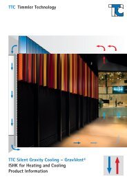
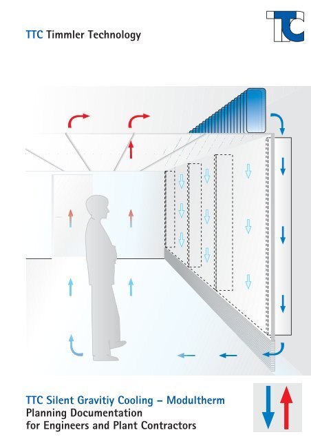
<strong>TTC</strong> <strong>Timmler</strong> <strong>Technology</strong><br />
<strong>TTC</strong> <strong>Silent</strong> <strong>Gravitiy</strong> <strong>Cooling</strong> <strong>–</strong> <strong>Modultherm</strong><br />
Planning Documentation<br />
for Engineers and Plant Contractors
<strong>TTC</strong> Order Key for <strong>Cooling</strong> Units<br />
2<br />
Order Key for <strong>TTC</strong> <strong>Cooling</strong> Units<br />
AASS 30 33 2 L 1<br />
Performance category<br />
1 = for construction height 33 (effective duct height H 1,5<strong>–</strong>6 m)<br />
eff.<br />
2 = for construction height 51 (effective duct height H 1,5<strong>–</strong>7 m)<br />
eff.<br />
Water connection<br />
L = Left<br />
R = Right<br />
Function<br />
2 = 2 pipe system<br />
Construction height [cm]<br />
33 > for series: AASS; ASVI; AISI; AVSI<br />
51 > for series: AASS; ASVI; AISI; AVSI<br />
Width [dm]<br />
08 - 10 - 12 - 14 - 16 - 18 - 20 - 22 - 24 dm<br />
Series<br />
AASS<br />
AISI<br />
AAVS<br />
AASI<br />
© 2004 <strong>TTC</strong> <strong>Timmler</strong> <strong>Technology</strong> GmbH.<br />
This document or any part thereof may not be reprinted, copied, or translated and figures and<br />
diagrams may not be used without prior written agreement from <strong>TTC</strong> <strong>Timmler</strong> <strong>Technology</strong> GmbH.<br />
Issued 02/2005. We reserve the right to make technical changes.
<strong>TTC</strong> Contents<br />
<strong>TTC</strong> <strong>Timmler</strong><br />
<strong>Technology</strong> GmbH<br />
Zum Wetterschacht 1<br />
D-45659 Recklinghausen<br />
Tel +49(0)23 61-9 15 96 80<br />
Fax +49(0) 23 61-9 15 96 89<br />
Email: info@ttc-technology.de<br />
http://www.ttc-technology.de<br />
General Information 4 <strong>–</strong> 5<br />
• Air-conditioning in general<br />
• <strong>TTC</strong> cooling units, function, advantages and applications<br />
Installation Examples 6 <strong>–</strong> 9<br />
• Installation options<br />
• Air inlets and outlets for <strong>TTC</strong> cooling units<br />
• <strong>TTC</strong> cooling units in primary air mode<br />
Technical Data and Information 10 <strong>–</strong> 11<br />
• Dimensions<br />
• Series<br />
• Weights<br />
Performance Diagrams 12 <strong>–</strong> 13<br />
• <strong>Cooling</strong> capacity for categories 1 and 2<br />
• Pressure drop on the water side<br />
• Formulae to calculate capacity<br />
Design Example 14 <strong>–</strong> 15<br />
• Water and air cooling<br />
• Pressure drop on the water side<br />
Accessories 16<br />
• Capacity reducing factors for <strong>TTC</strong> air inlet and outlet grating<br />
• Part no. for <strong>TTC</strong> air inlet and outlet grating<br />
Installation Instructions 17 <strong>–</strong> 18<br />
• Pipe installation for <strong>TTC</strong> cooling units<br />
• Reduced capacity through infiltrated air<br />
Order and Calculation Sheet 19<br />
for <strong>TTC</strong> <strong>Modultherm</strong> cooling units and accessories<br />
3
4<br />
<strong>TTC</strong> Information About Air Conditioning<br />
Advantages of <strong>TTC</strong> <strong>Modultherm</strong> cooling units<br />
Why do we air condition rooms? Is ventilation required?<br />
Advantages of <strong>TTC</strong> <strong>Modultherm</strong><br />
Working people spend the majority of<br />
their working life indoors. A maximum of<br />
physical and intellectual work is to be<br />
performed in this artificial environment.<br />
Studies with volunteers have shown that a<br />
persons productivity can be directly<br />
related to the thermal and air hygienical<br />
comfort of the room. In this context the<br />
air velocity, the relative humidity, the<br />
temperature gradient and the supply of<br />
primary air are of particular interest.<br />
Fig. 4.1-4.3 show mainly the results of<br />
studies by Prof. Ole Fanger and D. Wyon<br />
with a select number of volun-teers to<br />
determine peoples dissatisfaction with<br />
and acceptance of air-conditioning<br />
systems.<br />
Preferred cooling systems<br />
Either water or air is generally the carrier<br />
for the cooling energy. The following<br />
solutions are commonly used to cool down<br />
commercial premises:<br />
• Centrally treated and cooled primary air<br />
• <strong>Cooling</strong> of structural elements<br />
• Chilled ceiling systems<br />
• Wall and ceiling systems with cooling<br />
units or chilled beams<br />
• <strong>Cooling</strong> units or convectors combined<br />
with cooled primary air<br />
Intellectual Performance [%]<br />
95<br />
90<br />
85<br />
80<br />
75<br />
70<br />
65<br />
60<br />
22 23 24 25 26 27 28 29 30<br />
Room Temperature [°C]<br />
4.1 Intellectual performance at different<br />
room temperatures<br />
Issued 02/2005. We reserve the right to make technical changes.<br />
Relevant laws* and regulations* provide<br />
that commercially used spaces must have<br />
a primary airflow rate of approx. 6-9 m 3 /<br />
(h · m 2 ) or a change of air at 2-3 times the<br />
room volume to comply with air hygiene<br />
requirements. These minimal primary air<br />
streams can thus significantly reduce<br />
ventilation systems and save running and<br />
investment costs.<br />
*(Arbeitsstättenrichtlinie /German Work Place Directive, DIN<br />
1946 / Part 2 / Paragraph 3.2)<br />
4.2 Unhappiness at different temperatures<br />
Unhappy people [%]<br />
60<br />
40<br />
20<br />
10<br />
5<br />
1<br />
0,1<br />
Present in the room for 90 minutes<br />
Present in the room for 180 minutes<br />
0 1 2 3 4 5 6<br />
Temperature curve [K]<br />
Percentage of people who are unhappy with the<br />
rooms air conditioning, dependent on the:<br />
• floor level (ankle height) 0.1 m and<br />
head height (person is seated) 1.1m<br />
• No draughts, air speed 0.1-0.2 m/s<br />
• Condensation tray as standard, to<br />
prevent damage to furnishings and the<br />
building if condensation occurs<br />
• High fall ducts for the cooling air to<br />
provide high cooling capacity with<br />
a small space requirement<br />
• <strong>Silent</strong> operation without ventilation<br />
• Low running and investment costs for<br />
high comfort levels<br />
• Easy to upgrade if alterations are required<br />
• A wealth of design options for the<br />
room, for planners and architects<br />
• High thermal and hygienic comfort if<br />
combined with a primary air system<br />
• Additional to let area<br />
• Room temperatures can be individually<br />
controlled<br />
4.3 Acceptance with different airconditioning<br />
systems<br />
Unhappy People (%)<br />
40<br />
35<br />
30<br />
25<br />
20<br />
15<br />
10<br />
with RLT system<br />
without RLT system<br />
5<br />
0<br />
cooling ceiling* and<br />
distributed ventilation<br />
22 23 24 25 26 27 28<br />
Room temperature [°C]<br />
Acceptance with different air-conditioning systems<br />
and room temperatures. (A study by P. O.<br />
Fanger and D. Wyon)<br />
* Note! Instead of cooling ceilings, cooling units or<br />
cooling convectors could be used as an alternative.
<strong>TTC</strong> <strong>Modultherm</strong> <strong>Cooling</strong> System<br />
The functional principle of <strong>TTC</strong> <strong>Modultherm</strong><br />
Functional principle<br />
The functional principle of the <strong>TTC</strong> cooling units is based on the<br />
natural fact that warm and cold air have a different air density<br />
ρ [kg/m 3 ].<br />
At ceiling level warm air enters through the inlet grating (4) and<br />
is cooled down in the air cooler (1) through which cold water<br />
flows (see Fig. 5.1). If operated at high humidity, e.g. in a hotel<br />
room, special production rooms or when operated with-out preconditioned<br />
primary air a conden-sation tray is supplied as<br />
standard under-neath the air cooler. Through the fall duct (2)<br />
and an attractive air outlet (3) the cooled air is returned to the<br />
room.<br />
This cooled air is then warmed up again by heat sources in the<br />
room, e.g. people, lighting, computers and other electrical and<br />
electronic equipment, sunrays through the windows, the warmth<br />
of the walls and rises to the ceiling.<br />
The air velocity generated in the room through thermal<br />
conditions is very low and can only be measured with special<br />
equipment. This minute air circulation results in high thermal<br />
comfort levels and minimum temperature gradients in the<br />
occupied zone. The characteristic curves shown in the capacity<br />
diagrams on pages 12-14 are based on test rig measurements<br />
and were carried out under defined installation and operating<br />
conditions.<br />
Differing constructional conditions will need to be taken into<br />
account when determining the cooling performance of cooling<br />
units. <strong>TTC</strong> will be happy to help you with your calculations.<br />
H wirks.<br />
12<br />
11<br />
2<br />
1<br />
T erf.<br />
4<br />
3<br />
Performance factors<br />
The performance of the <strong>TTC</strong> cooling units depends on many<br />
factors, for example:<br />
• The effective fall duct height, H eff.<br />
• The fall duct depth D req. (for unit height 330 = 100 mm and<br />
for unit height 510 = 150 mm)<br />
• Spacing between sealing off walls (desired 600-800 mm,<br />
see page 17)<br />
• Smooth surface of the fall ducts and sealing off walls<br />
• Prevention of infiltrated air<br />
• Duct insulation on front and rear walls<br />
• The free cross-section of the inlet and outlet gratings (at<br />
least 70% of the visible surface of the finned cooling unit).<br />
For other cross-sections see the chapter Reduced<br />
Performance on page 16<br />
• Median temperature difference ∆ϑ m [K] between air intake<br />
and median temperature of the cooling medium<br />
• Water viscosity and quality (VDI 2025)<br />
• Flow path restriction caused by the pipe work or structural<br />
obstacles<br />
• Redirection of the cool air flow<br />
Area of application<br />
<strong>TTC</strong> <strong>Modultherm</strong> cooling units are ideally suited for all areas of<br />
application, where silent and efficient control of temperature is<br />
required:<br />
Small and open plan offices, Conference rooms, Computer<br />
rooms, Recording and TV studios, Hotel rooms, Public access<br />
areas, Reception areas, Department stores, Printing and paper<br />
works, Assembly and production facilities, to remove heat from<br />
electronic or electrical control cabinets, etc.<br />
10<br />
5.1 Room airflow in cooling<br />
mode using <strong>TTC</strong> cooling units<br />
(1) Air cooler incl. condensation<br />
tray<br />
(2) Fall duct for cold air<br />
(3) Air opening (min. 70 % free<br />
cross-section of the air cooler<br />
visible area)<br />
(4) Air inlet grating (min. 70 %<br />
free cross-section of the air<br />
cooler visible area)<br />
(10) False floor convector for<br />
heating mode<br />
(11) Required fall duct depth Dreq. (12) Effective fall duct height Heff. Issued 02/2005. We reserve the right to make technical changes.<br />
5
<strong>TTC</strong> Installation Examples<br />
Fig. 6.1 shows the installation of an AASS unit in a TV studio or a<br />
test centre on a wall (dry construction wall installed in post-andbeam<br />
construction).<br />
Key to 6.1<br />
14<br />
1<br />
4<br />
(1) <strong>Cooling</strong> unit incl. condensation tray to collect condensate in<br />
2<br />
dehumidification mode<br />
(2) Fall duct with sealing off walls (5) (spacing 600-800 mm)<br />
The minimum depth D is 100mm for unit height 33 and<br />
req.<br />
5<br />
150mm for unit height 51<br />
(6) Floor outlet grating with a free cross-section of 70 % of the<br />
visible area of the finned air cooler<br />
(4) Air inlet grating with a free cross-section of 70% of the<br />
visible area of the finned air cooler<br />
9<br />
(5) Sealing off walls to stabilize the cold air flow<br />
(9) Mixing desk or test console in studios or test centres<br />
Note!<br />
The minimum requirements under 2, 3 and 4.1 must be complied<br />
with to ensure the quoted capacities.<br />
6<br />
For other free cross-sections see page 16 or contact <strong>TTC</strong>. 6.1 Room air flow with <strong>TTC</strong> cooling units in cooling mode<br />
Fig. 6.2-6.4 show three options for the air intake. Other options<br />
are available, please contact <strong>TTC</strong>.<br />
Fig. 6.2 shows the air flow to the cooling unit (1) via an air inlet<br />
grating (4) which has been integrated into a false ceiling.<br />
In Fig. 6.3 the air inlet grating has been replaced by an air gap<br />
(7) in the false ceiling.<br />
Fig. 6.4 shows ceiling panels with slits for the air intake.<br />
Optionally slots may also be placed at the ceiling edges.<br />
Key to 6.2-6.4<br />
(1) <strong>Cooling</strong> unit incl. condensation tray to collect condensate in<br />
dehumidification mode<br />
(2) Fall duct with sealing off walls (5) (spacing 600-800 mm)<br />
The minimum depth D req. is 100mm for unit height 33 and<br />
150mm for unit height 51<br />
(4) Air inlet grating with a free cross-section of 70% of the<br />
visible area of the finned air cooler<br />
(7) Air gap in the false ceiling (70% free cross-section)<br />
(8) Ceiling panels with air slits (free cross-section, 70% or the<br />
visible area of the finned air cooler)<br />
Gaps between wall and ceiling (not shown)<br />
Note!<br />
The minimum requirements under 2, 4, 7 and 8 must be complied<br />
with to ensure the quoted capacities.<br />
For other free cross-sections see page 16 or contact <strong>TTC</strong>.<br />
6<br />
Example 1: <strong>Cooling</strong> unit on a wall<br />
Example 2: Air intake for cooling units<br />
Issued 02/2005. We reserve the right to make technical changes.<br />
2<br />
1<br />
6.2 Air intake through air inlet gratings in a false ceiling<br />
1<br />
2 7<br />
6.3 Air intake through an air gap in the false ceiling<br />
2<br />
1<br />
6.4 Air intake through ceiling panels<br />
4<br />
8
<strong>TTC</strong> Installation Examples<br />
2<br />
1<br />
5<br />
4<br />
3<br />
4<br />
7.1 Room air flow with <strong>TTC</strong> cooling units in cooling mode<br />
2<br />
1<br />
5<br />
3<br />
4<br />
7.2 Air being released into the room through wall and floor<br />
gratings<br />
Example 3: <strong>Cooling</strong> unit behind a screen<br />
This example (Fig. 7.1) illustrates the installation of an AASS<br />
cooling unit above a cupboard or shelves.<br />
Key to 7.1<br />
(1) <strong>Cooling</strong> unit AASS incl. condensation tray to collect<br />
condensate in dehumidification mode<br />
(2) Fall duct with sealing off walls (5) (spacing 600-800 mm)<br />
The minimum depth, D req. is 100mm for unit height 33 and<br />
150mm for unit height 51<br />
(3) Air outlet grating with a free cross-section of 70% of the<br />
visible area of the finned air cooler<br />
(4) Screened air inlet grating (the free air intake should be 70%<br />
of the visible area of the finned air cooler)<br />
(5) Sealing off walls to stabilize the cold air flow<br />
Note!<br />
The minimum requirements under 2, 3 and 4 must be complied<br />
with to ensure the quoted performances.<br />
For other free cross-sections see page 16 or contact <strong>TTC</strong>.<br />
Example 4: Air outlet grating into the room<br />
Fig. 7.2 illustrates the option for air to be dispersed into the<br />
room through an air outlet grating (3). This type of air flow into<br />
the room ensures a good, even temperature distribution.<br />
To dimension the floor air outlets consultation with a ventilation<br />
engineer is recommended.<br />
Key to 7.2<br />
(1) <strong>Cooling</strong> unit AASS incl. condensation tray to collect<br />
condensate in dehumidification mode<br />
(2) Fall duct with sealing off walls (5) (spacing 600-800 mm)<br />
The minimum depth D req. is 100mm for unit height 33 and<br />
150mm for unit height 51<br />
(3) Air outlet grating with a free cross-section of 70% of the<br />
visible area of the finned air cooler<br />
(4) Air inlet grating with a free cross-section of 70% of the<br />
visible area of the finned air cooler<br />
Note!<br />
The minimum requirements under 3 and 4 must be complied<br />
with to ensure the quoted performance.<br />
For other free cross-sections see page 16 or contact <strong>TTC</strong>.<br />
Issued 02/2005. We reserve the right to make technical changes.<br />
7
<strong>TTC</strong> Installation Examples<br />
8<br />
Example 5: <strong>Cooling</strong> unit integrated into the duct<br />
Fig. 8.1 shows the AISI cooling unit (1) integrated into a fall<br />
duct (2). On the room side the cooling unit is screened by an<br />
architecturally appealing air inlet grating which should have a<br />
free cross-section of 70%. For this type of installation a<br />
mounting frame is supplied as standard. The top joint to the<br />
bare ceiling is formed, for example, by a waffle-type ceiling at<br />
the discretion of the architect and client.<br />
Key to 8.1<br />
(1) <strong>Cooling</strong> unit AISI incl. condensation tray to collect<br />
condensate in dehumidification mode<br />
(2) Fall duct with sealing off walls 5 (spacing 600<strong>–</strong>800 mm)<br />
The minimum depth D req. is 100mm for unit height 33 and<br />
150mm for unit height 51<br />
(3) Air outlet grating with a free cross-section of 70% of the<br />
visible area of the finned air cooler<br />
(4) Air inlet grating with a free cross-section of 70% of the<br />
visible area of the finned air cooler<br />
(5) Sealing off walls to stabilize the cold air flow<br />
Note!<br />
The minimum requirements under 2, 3 and 4 must be complied<br />
with to ensure the quoted performance.<br />
For other free cross-sections see page 16 or contact <strong>TTC</strong>.<br />
2<br />
1<br />
5<br />
3<br />
5<br />
4<br />
2<br />
1<br />
5<br />
3<br />
8.1 <strong>TTC</strong> cooling unit integrated in the duct<br />
Example 6: <strong>Cooling</strong> unit on a wall with dispersed air outlet at the window<br />
Fig. 8.2 shows the cooling unit AASS (1)<br />
above a fall duct (2). On the room side the<br />
cooling unit is screened by an<br />
architecturally appealing air inlet grating<br />
(4) which should have a free cross-section<br />
of 70%.<br />
The air is returned to the room through a<br />
floor grating at the window. This type of<br />
installation always requires a false floor.<br />
Key to 8.2<br />
Items (1), (2), (4) are (5) equivalent to<br />
Fig. 8.1.<br />
(6) Floor grating integrated into the false<br />
floor as a dispersed air outlet.<br />
Note!<br />
The minimum requirements under 2, 3 and<br />
4 must be complied with to ensure the<br />
quoted performance.<br />
For other free cross-sections see page 16<br />
or contact <strong>TTC</strong>.<br />
Issued 02/2005. We reserve the right to make technical changes.<br />
8.2 Air distribution via air dispersal outlet in the floor<br />
4<br />
6
<strong>TTC</strong> Installation Examples<br />
Example 7: <strong>Cooling</strong> unit in a false ceiling with additional primary air mode Function<br />
Function<br />
Example 7 (Fig. 9.1) shows how <strong>TTC</strong> units may be combined with a primary air system.<br />
Via the primary channel (8) conditioned outdoor air is blown at low speed into the fall<br />
ducts via channels or pipes. If suitable silencers are used the sound pressure level can<br />
be kept below 30 (dBA).<br />
Installation<br />
The cooling unit (1) can be installed on a wall between the bare and the false ceiling,<br />
on a cupboard or shelves. Design options showing how the cooling units could be<br />
covered on the room side are shown on page 6 (Fig. 6.2-6.4).<br />
For the primary air intake the following variants would be suitable:<br />
• Air outlet gratings (3) in walls, cupboards or shelves<br />
• Air outlet gratings in the false floor, see Fig. 8.1 on page 8<br />
• Dispersed air outlets<br />
Outdoor air flow<br />
In rooms to be occupied by people the outdoor air flow needs to be sized dependent on<br />
how many people are present in the room at the same time and what the room is used<br />
for (see the table on the right).<br />
The outdoor air flow is frequently provided at 2.5-3 times the change of room air.<br />
At the maximum outdoor temperature values (see DIN 4701 / parts 1 and 2 as well as<br />
VDI 2078) the outdoor air flow can be reduced by 50% of the minimum outdoor air<br />
flow per person. For rooms with additional pollution through smells (e.g. tobacco<br />
smoke) the minimum outdoor air flow is increased by 20 m3 /h per person.<br />
4<br />
3<br />
5<br />
1<br />
2<br />
13<br />
Minimum primary air flow per person<br />
and hour*<br />
Room type m3 /h<br />
Small office 30<br />
Open plan office 50<br />
Theatre/concert hall 20<br />
Canteen 30<br />
Conference room 30<br />
Cinema 20<br />
Banqueting hall 20<br />
Rest room 30<br />
Break room 30<br />
Class room 30<br />
Reading room 20<br />
Lecture theatre 30<br />
Show room 20<br />
Shop 20<br />
Museum 20<br />
Hotel room 30<br />
Public house/restaurant<br />
Gymnastic and sport hall<br />
40<br />
with seating for spectators 20<br />
*) in accordance with DIN 1946 / Part 2 /Paragraph<br />
3.2<br />
9.1 <strong>TTC</strong> <strong>Modultherm</strong> cooling unit with<br />
primary air mode<br />
(1) Air cooler incl. condensation tray<br />
(2) Fall duct for cold air<br />
(3) Air outlet grating (min. 70% free<br />
cross-section of the visible area of<br />
the air cooler)<br />
(4) Air inlet grating (min. 70% free crosssection<br />
of the visible area of the air<br />
cooler)<br />
(5) Sealing off walls to stabilize the cold<br />
air flow<br />
(13) Primary air channel<br />
Issued 02/2005. We reserve the right to make technical changes.<br />
9
<strong>TTC</strong> Dimensions and Information<br />
AASS 33 (51)** series<br />
Design<br />
(1) Air cooler made of copper pipes with<br />
aluminium fins, max. operating<br />
temperature 90 0C, max. operating<br />
pressure 10 bar<br />
(2) Housing completely made of<br />
galvanized steel plate<br />
(3) Water connection with R 3/4“, torsion<br />
protection<br />
(4) Condensation tray to collect<br />
condensate in dehumidification mode<br />
(5) Condensate drain, ø12 mm, mounted<br />
on the condensate tray and supplied as<br />
standard<br />
Installation<br />
The cooling unit can be installed above<br />
shafts, cupboards or shelves. For examples<br />
see pages 6-9.<br />
Important: To ensure optimum operation<br />
sealing off walls spaced at 600 to 800 mm<br />
need to be installed in the fall ducts.<br />
10<br />
AAVS 33/51** series<br />
Design<br />
(1) Air cooler made of copper pipes with<br />
aluminium fins, max. operating<br />
temperature 90 0 C, max. operating<br />
pressure 10 bar<br />
(2) Housing completely made of<br />
galvanized steel plate incl. mounting<br />
frame (6)<br />
(3) Water connection with R 3/4“, torsion<br />
protection<br />
(4) Condensation tray to collect<br />
condensate in dehumidification mode<br />
(5) Condensate drain, ø12 mm, mounted<br />
on the condensate tray and supplied as<br />
standard<br />
(6) Mounting frame made of galvanized<br />
steel sheet, supplied as standard<br />
Installation<br />
The mounting frame is used to install the<br />
cooling unit in front of the fall duct wall.<br />
Important: To ensure optimum operation<br />
sealing off walls spaced at 600 to 800 mm<br />
need to be installed in the fall ducts.<br />
Issued 02/2005. We reserve the right to make technical changes.<br />
10.1<br />
Part no: AASS .. ..**) 08 10 12 14 16 18 20 22 24<br />
Finned length L finned [mm] 720 920 1120 1320 1520 1720 1920 2120 2320<br />
Total unit length L tot. [mm] 800 1000 1200 1400 1600 1800 2000 2200 2400<br />
Total weight (33) ≈ [kg] 26 32 39 46 52 59 65 72 79<br />
Total weight (51) ≈ [kg] 39 49 59 69 80 90 100 110 120<br />
**) see order key on page 2<br />
10.2<br />
3<br />
40<br />
40<br />
*) Dimensions in brackets are for construction height 51<br />
Part no: AAVS .. ..**) 08 10 12 14 16 18 20 22 24<br />
Finned length L finned [mm] 720 920 1120 1320 1520 1720 1920 2120 2320<br />
Total unit length L tot. [mm] 800 1000 1200 1400 1600 1800 2000 2200 2400<br />
Total weight (33) ≈ [kg] 24 30 37 44 50 57 63 70 77<br />
Total weight (51) ≈ [kg] 37 47 57 67 78 88 98 108 118<br />
**) see order key on page 2<br />
2<br />
1<br />
1<br />
2<br />
Finned length Lfinned<br />
Frame length FL<br />
Finned length Lfinned<br />
Frame length FL<br />
4<br />
330 (510)*<br />
300 (510)*<br />
*) Dimensions in brackets are for construction height 51<br />
5<br />
25<br />
105<br />
5<br />
50<br />
30<br />
Ø12 mm<br />
200<br />
1<br />
5<br />
150<br />
5<br />
80<br />
3<br />
300<br />
4<br />
30<br />
100<br />
(150)*<br />
6<br />
100<br />
(150)*
<strong>TTC</strong> Dimensions and Information<br />
11.1<br />
Part no: AISI .. ..**) 08 10 12 14 16 18 20 22 24<br />
Finned length L finned [mm] 720 920 1120 1320 1520 1720 1920 2120 2320<br />
Total unit length L tot. [mm] 800 1000 1200 1400 1600 1800 2000 2200 2400<br />
Total weight (33) ≈ [kg] 23 29 36 43 49 56 62 69 76<br />
Total weight (51) ≈ [kg] 36 46 56 66 77 87 97 107 117<br />
**) see order key on page 2<br />
11.2<br />
3<br />
40<br />
3<br />
40<br />
Part no: AASI .. ..**) 08 10 12 14 16 18 20 22 24<br />
Finned length L finned [mm] 720 920 1120 1320 1520 1720 1920 2270 2320<br />
Total unit length L tot. [mm] 800 1000 1200 1400 1600 1800 2000 2200 2400<br />
Total weight (33) ≈ [kg] 23 29 36 43 49 56 62 69 76<br />
Total weight (51) ≈ [kg] 36 46 56 66 77 87 97 107 117<br />
**) see order key on page 2<br />
5<br />
345 (525)*<br />
*) Dimensions in brackets are for construction height 51<br />
2<br />
5<br />
2<br />
Finned length Lfinned<br />
Frame length FL<br />
50<br />
Finned length Lfinned<br />
Frame length FL<br />
50<br />
25<br />
Ø 12 mm<br />
225<br />
(405)*<br />
145<br />
(325)*<br />
45<br />
25<br />
Ø 12 mm<br />
145<br />
(325)*<br />
*) Dimensions in brackets are for construction height 51<br />
6<br />
30<br />
70<br />
70<br />
153<br />
1<br />
4<br />
1<br />
4<br />
153<br />
30<br />
6<br />
345 (525)*<br />
225<br />
(405)*<br />
AISI 33 (51)** series<br />
Design<br />
(1) Air cooler made of copper pipes with<br />
aluminium fins, max. operating<br />
temperature 90 0C (2) Housing completely made of<br />
galvanized steel plate incl. mounting<br />
frame (6)<br />
(3) Water connection R 3/4“ torsion<br />
protection<br />
(4) Condensation tray to collect<br />
condensate in dehumidification mode<br />
(5) Condensate drain, ø12 mm,<br />
mounted on the condensate tray and<br />
supplied as standard<br />
(6) Mounting frame made of galvanized<br />
steel sheet, supplied as standard<br />
Installation<br />
The cooling unit is installed in the fall<br />
duct for the cold air (see page 8).<br />
Important: To ensure optimum operation<br />
sealing off walls spaced at 600 to 800 mm<br />
need to be installed in the fall ducts.<br />
AASI 33 (51)** series<br />
Design<br />
(1) Air cooler made of copper pipes with<br />
aluminium fins, max. operating<br />
temperature 90 0C, max. operating<br />
pressure 10 bar<br />
(2) Housing completely made of<br />
galvanized steel plate incl. mounting<br />
frame (6)<br />
(3) Water connection R 3/4“ torsion<br />
protection<br />
(4) Condensation tray to collect<br />
condensate in dehumidification mode<br />
(5) Condensate drain, ø12 mm,<br />
mounted on the condensate tray and<br />
supplied as standard<br />
(6) Mounting frame made of galvanized<br />
steel sheet, supplied as standard<br />
Installation<br />
The mounting frame is used to install the<br />
cooling unit in front of the fall duct wall.<br />
Important: To ensure optimum operation<br />
sealing off walls spaced at 600 to 800 mm<br />
need to be installed in the fall ducts.<br />
Issued 02/2005. We reserve the right to make technical changes.<br />
11
<strong>TTC</strong> Capacity Diagrams<br />
Category 1<br />
Specific cooling capacity: category 1 Specific pressure drop heat exchanger: category 1<br />
1700<br />
1600<br />
1500<br />
1400<br />
1300<br />
1200<br />
1100<br />
1000<br />
900<br />
800<br />
700<br />
600<br />
500<br />
400<br />
300<br />
280<br />
200<br />
100<br />
12.1<br />
12<br />
Category 1 (cooling)<br />
2,2 m<br />
6 7 8 9 10 11 12 13<br />
Median temperature difference ∆ϑ [K] m<br />
6,0 m<br />
5,0 m<br />
4,0 m<br />
3,5 m<br />
3,0 m<br />
2,5 m<br />
2,0 m<br />
1,5 m<br />
Formula to calculate the median temperature difference ∆ϑ m<br />
1<br />
<<br />
Specific cooling capacity q spec. [W/m]<br />
.<br />
<<br />
<<br />
t [°C] + t [°C]<br />
W1 W2 ∆ϑ [K] = t <strong>–</strong> for cooling mode<br />
m R<br />
2<br />
∆ϑ m [K] = median temperature difference between cooling<br />
medium and room temperature<br />
t W1 [°C] = cold water inlet<br />
t W2 [°C] = cold water outlet<br />
t R [°C] = room temperature<br />
Issued 02/2005. We reserve the right to make technical changes.<br />
<<br />
15<br />
10<br />
8<br />
6<br />
5<br />
4<br />
3<br />
2<br />
1,0<br />
0,8<br />
0,6<br />
0,5<br />
0,4<br />
0,3<br />
0,2<br />
0,1<br />
0,08<br />
0,06<br />
kg/h 10<br />
kg/s<br />
12.3<br />
.<br />
< ><br />
Specific pressure drop ∆p w specif. [kPa/m] finned<br />
0,003<br />
15<br />
20<br />
25 30 40 50 60 80 100 150 200 300 400 500 700<br />
0,005 0,007 0,01 0,015 0,02 0,03 0,04 0,06 0,08 0,1 0,15 0,20<br />
.<br />
< Water mass flow mw ><br />
Formula to calculate the overall sensitive cooling capacity of<br />
the <strong>TTC</strong> <strong>Modultherm</strong> cooling unit<br />
3<br />
. .<br />
Q [W] = q [W/m] · L [m]<br />
K(tot.) K(spec.) finned<br />
·<br />
QK.(tot.) .<br />
qspecif. [W]<br />
[W/m]<br />
= total cooling capacity of a cooling unit<br />
= specific cooling capacity of a cooling unit<br />
Lfinned [m] = finned length of the cooling unit<br />
.<br />
Formula to calculate the specific water mass flow mw · q [kW] · L [m]<br />
·<br />
(specif.) finned<br />
4 m<br />
·<br />
[kg/h] = 860 ·<br />
W t - t [K]<br />
W2 W1<br />
Formula to calculate the overall pressure drop ∆p of the<br />
w(tot.)<br />
cooling unit on the water side<br />
.<br />
.<br />
·<br />
5 ∆p [kPa] = ∆p [kPa/m] • L [m]<br />
w(tot.) w(spec.) finned<br />
∆p. [kPa/m] = see figure 12.3<br />
w(specif.)
<strong>TTC</strong> Performance Diagrams<br />
Category 2<br />
Specific cooling capacity: category 2 Specific pressure drop heat exchanger: category 2<br />
2600<br />
2500<br />
2400<br />
2300<br />
2200<br />
2100<br />
2000<br />
1900<br />
1800<br />
1700<br />
1600<br />
1500<br />
1400<br />
1300<br />
1200<br />
1100<br />
1000<br />
900<br />
800<br />
700<br />
600<br />
500<br />
435<br />
400<br />
300<br />
200<br />
13.1<br />
Specific cooling capacity q spec. [W/m]<br />
.<br />
<<br />
<<br />
Category 2 (cooling)<br />
<<br />
2,2 m<br />
6 7 8 9 10 11 12 13 14 15 16<br />
7,0 m<br />
6,0 m<br />
Median temperature difference ∆ϑ m [K]<br />
5,0 m<br />
4,0 m<br />
3,5 m<br />
3,0 m<br />
2,5 m<br />
2,0 m<br />
1,5 m<br />
Formula to calculate the overall pressure drop ∆p of the<br />
w(tot.)<br />
cooling unit on the water<br />
.<br />
.<br />
5 ∆p [kPa] = ∆p [kPa/m] • L [m]<br />
w(tot.) w(spec.) finned<br />
.<br />
∆p [kPa/m] = see Fig. 12.3<br />
w(spec.)<br />
<<br />
15,0<br />
10,0<br />
8,0<br />
6,0<br />
5,0<br />
4,0<br />
3,0<br />
2,0<br />
1,5<br />
1,0<br />
0,8<br />
0,6<br />
0,5<br />
0,4<br />
0,3<br />
0,2<br />
0,1<br />
0,09<br />
0,08<br />
0,06<br />
0,05<br />
0,04<br />
0,03<br />
0,02<br />
kg/h<br />
217 kg/h<br />
50 60 80 100 150 200 300 400 500 700 1000 1500 2000 3000 4000<br />
kg/s<br />
13.3<br />
0,015 0,02 0,03 0,04 0,06 0,08 0,1 0,15 0,20 0,30 0,40 0,6 0,8 01,0 1,4<br />
Formula to calculate the medium temperature difference ∆ϑ m<br />
1<br />
.<br />
< ><br />
Specific pressure drop ∆p w specif. [kPa/m]<br />
t [°C] + t [°C]<br />
W1 W2<br />
∆ϑ [K] = t <strong>–</strong> for cooling mode<br />
m R 2<br />
∆ϑ m [K] = median temperature difference between cooling<br />
medium and room temperature<br />
t W1 [°C] = cold water inlet<br />
t W2 [°C] = cold water outlet<br />
t R [°C] = room temperature<br />
Formula to calculate the overall sensitive cooling capacity of<br />
the <strong>TTC</strong> <strong>Modultherm</strong> cooling unit<br />
3<br />
. .<br />
Q [W] = q [W/m] · L [m]<br />
K(tot.) K(spec.) finned<br />
·<br />
Q [W] K.(tot.)<br />
.<br />
q [W/m] spec.<br />
= total cooling capacity of a cooling unit<br />
= specific capacity of a cooling unit<br />
L [m] finned = finned length of a cooling unit<br />
Formula to calculate the specific water mass flow mw 4 m· [kg/h] = 860 ·<br />
W<br />
·<br />
·<br />
q [kW] · L [m]<br />
(spec.) finned<br />
t - t [K]<br />
W2 W1<br />
<<br />
.<br />
Water mass flow mw Issued 02/2005. We reserve the right to make technical changes.<br />
><br />
13
<strong>TTC</strong> Design Example<br />
Example 1: Dimensioning a cooling unit for cooling mode<br />
Calculation assumptions ><br />
Calculate ∆ϑ m<br />
Determine q· K(spec.)<br />
Required ribbed width, L finned ><br />
Required <strong>TTC</strong> cooling units ><br />
<strong>Cooling</strong> performance on the<br />
water side ><br />
Result ><br />
14<br />
><br />
><br />
Task:<br />
An office (see page 15, Fig. 15.1) with a sensitive cooling load Q = 2.000 W is to be cooled<br />
K(sen.)<br />
with AASS or AVSI series cooling units and also to be ventilated with additional, pre-conditioned<br />
primary air. The unit is to be installed above a range of cupboards or a set of shelves at a height of<br />
2.5m (see Fig. 15.1). The room volume is approx. 80 m3 . The pre-conditioned primary air is blown<br />
into the room at 180 ·<br />
C through flexible pipes in the fall ducts.<br />
• Cold water temperatures: t = 16 W1 0C and t = 20 W2 0C • Room temperature: t = 26 ºC<br />
R<br />
• Primary air temperature: t = 18 ºC<br />
L(ZU)<br />
• Max. possible installation length L for the cooling unit(s) = 5.50 m<br />
max.<br />
• The primary air rate, V is 240 m A(prim) 3 ·<br />
/h at 3 times room air change<br />
• The sound pressure level shall not exceed 30 dB(A)<br />
• The effective fall duct hight H ≈ 2.2 m<br />
eff.<br />
Step-by-step illustration of the solution:<br />
1. Calculate the median temperature difference ∆ϑ with the following formula<br />
m<br />
∆ϑ = t - [(t + t ) : 2] (see pages 12/13, equation 1)<br />
m R W1 W2<br />
∆ϑ = 26 - [(16 + 20) : 2] = 8 K<br />
m<br />
2. For ∆ϑ = 8 K take the specific cooling values q<br />
·<br />
from the diagrams for capacity<br />
m Conv.(spec.)<br />
categories „1“ and „2“ (see page 12/13):<br />
• Category „1“ = 280 W/m<br />
• Category „2“ = 435 W/m<br />
this results in:<br />
a) required finned length, L for category 1 = 2000 W : 280 W/m ≈ 7.15 m<br />
finned<br />
b) required finned length, L for category 2 = 2000 W : 435 W/m ≈ 4.60 m<br />
finned<br />
Conclusion:<br />
• Due to structural restrictions (max. 5.5m) the length required under a), L = 7m, cannot be<br />
finned<br />
used<br />
• The length calculated under b), L = 4.6 m meets the requirement<br />
finned<br />
3. Select the required <strong>TTC</strong> cooling units<br />
• Max. available <strong>TTC</strong> cooling unit length, L total = 2.4 m with L finned = 2.32 m<br />
• To fulfil the requirement you will need 2 <strong>TTC</strong> performance category 2 cooling units<br />
2 off: AASS.24.51.2._.2 (see order key on page 2)<br />
4. Calculation to check the actual cooling capacity on the water side<br />
·<br />
Q [W] = q [W/m] · W [m] · n [units]<br />
K(total) spec. finned<br />
·<br />
= 435 · W/m · 2.32 m · 2 ≈ 2020 W = 2.02 kW (required 2.000 kW)<br />
Q K(total.)<br />
<strong>Cooling</strong> power of the primary air > 5. Calculate the additional cooling capacity from the primary air<br />
·<br />
V [m A(tot.)<br />
Q (kW) = K(air) = 0.64 kW<br />
3 /h] · r [kg/m . L 3 ]· cp[kJ/kg·K] · ∆t [K]<br />
L L<br />
3600<br />
240 (m3 /h) · 1,2 (kg/m . 3 ·<br />
Q [kW] =<br />
K(air)<br />
·<br />
) · 1 (kJ/kg·K) · 8 (K)<br />
3600<br />
Overall cooling power > 6. In total the cooling capacity on the water and air side:<br />
.<br />
Q = 2.02 kW (step4 4) + 0,64 kW (step 5) = 2.66 kW<br />
K(water,air)<br />
Please note ><br />
Issued 02/2005. We reserve the right to make technical changes.<br />
• If <strong>TTC</strong> Gratings are used as air inlets and outlets (see page 16) the cooling power calculated<br />
under point 4 must be multiplied by the correction factors in tables 16.1-16.7.
<strong>TTC</strong> Design Example<br />
Example 2: How to calculate the pressure drop on the water side<br />
Calculation assumptions ><br />
Result water mass flow ><br />
Specific pressure drop ><br />
Result ∆p w(tot.)<br />
><br />
Task<br />
To calculate the pressure drop on the water side, ∆p of the cooling unit with part no:<br />
W(total)<br />
AASS.24.51.2._.2 in example 1 (page 14)<br />
Parameters required for the calculation:<br />
• Cold water temperatures: t = 16 ºC; t = 20 ºC<br />
W1 W2<br />
• Finned length of the cooling unit, L = 2.32 m<br />
finned<br />
·<br />
• Specific cooling capacity q = 435 W/m (see page 14, calculation step 2)<br />
K(spec.)<br />
Solution<br />
.<br />
The water pressure drop is approximated via the water mass flow m using equation 4 (see page<br />
W<br />
13)<br />
·<br />
m W [kg/h] = 860 ·<br />
·<br />
q [kW/m] · L [m]<br />
(spezif.) finned<br />
t - t [K]<br />
W2 W1<br />
0,435 kW/m · 2,32 m<br />
20 0C - 16 0 m<br />
·<br />
= 860 · ≈ 217 kg/h<br />
W<br />
C<br />
From diagram 13.3 (page 13) take the<br />
specific hydraulic pressure drop ∆p w(spec.) ≈ 0,09 kPa/m<br />
The total water pressure drop ∆p W(total) for the cooling unit (L finned = 2.32 m) is:<br />
∆p w(ges.) [kPa] = ∆p w(spezif.) [kPA/m] · L finned [m]<br />
∆p w(total) = 0.09 kPa/m · 2.32 m ≈ 0.21 kPa<br />
3. Illustration of the system calculated in examples 1 and 2<br />
15.1<br />
(1) Air cooler with condensation tray<br />
(2) Fall duct for cold air<br />
(3) Air outlet grating<br />
(4) Air inlet grating<br />
(8) Primary air channel<br />
(AL) Sealing batten against infiltrated air<br />
Note!<br />
For other free cross-sections of the air inlet<br />
and air outlet gratings please refer to page<br />
16 or contact <strong>TTC</strong>.<br />
Issued 02/2005. We reserve the right to make technical changes.<br />
15
<strong>TTC</strong> Air Inlet and Outlet Gratings<br />
Order no.<br />
Reduced performance of the <strong>TTC</strong> air outlets in conjunction with <strong>TTC</strong> cooling units<br />
<strong>TTC</strong> Air inlet and outlet gratings Rod free Reduced performance factors ”f“<br />
All figures are based on the cooling unit and the air outlet<br />
graving being identical in length. The heights of the cooling<br />
units are for a grating height of 200mm in line with the<br />
spacing<br />
”a“<br />
crosssection<br />
<strong>TTC</strong> <strong>Modultherm</strong> cooling unit series<br />
AASS AASS AAVS AAVS AISI AISI AVSI AVSI<br />
preliminary documentation.<br />
mm % 33 51 33 51 33 51 33 51<br />
Note: The cooling power of the cooling unit in the diagrams (pages 12 and 13) must be corrected by the reduced performance factors<br />
”f“ stated in tables 16.1-16.7 if the above air inlet and outlet gratings are used. The reduced performance factors ”f“ are dependent<br />
on the type and the free cross-section of the gratings. The following formula is to be used:<br />
Q K(reduced) = Q K(1unit) · f min<br />
QK(reduced) QK(1unit) fin = reduced cooling capacity<br />
= calculated cooling capacity p.unit<br />
= for in flowing room air<br />
= for out flowing cooling air<br />
Example<br />
Q = 1.01 kW (see example on page 12)<br />
K(1unit)<br />
f = 0.84 (Table 16.3, Type AASS 51)<br />
in<br />
f = 0.84 (Table 16.3, Type AASS 51)<br />
out<br />
=> f = 0.84<br />
min<br />
f out<br />
Issued 02/2005. We reserve the right to make technical changes.<br />
16<br />
16.1<br />
16.2<br />
a a<br />
a a<br />
16.3<br />
a a<br />
16.4<br />
a a<br />
Longitudinal gratings rigid (full<br />
profile), made of aluminium, for<br />
air inlets and outlets in ceilings,<br />
walls and on the floor<br />
Comb gratings rigid (full<br />
profile), made of aluminium or<br />
V2A, for air inlets and outlets in<br />
ceilings, walls and on the floor<br />
Part no: <strong>TTC</strong>-KSF ❐ Alu ❐ V2A<br />
Comb gratings rigid (T-profile),<br />
(full profile), made of aluminium,<br />
for air inlets and outlets in<br />
ceilings, walls and on the floor<br />
Part no: <strong>TTC</strong>-KST ❐ Alu<br />
Comb gratings rigid (U-profile),<br />
(full profile), made of V2A or aluminium,<br />
for air inlets and outlets<br />
in ceilings, walls and on the floor<br />
20 88 0.94 0.84 0.94 0.84 0.94 0.84 0.94 0.84<br />
15 83 0.93 0.82 0.93 0.82 0.93 0.82 0.93 0.82<br />
10 77 0.92 0.81 0.92 0.81 0.92 0.82 0.92 0.81<br />
20 87 0.94 0.83 0.94 0.83 0.94 0.83 0.94 0.83<br />
15 83 0.93 0.82 0.93 0.82 0.93 0.82 0.93 0.82<br />
10 77 0.92 0.81 0.92 0.81 0.92 0.82 0.92 0.81<br />
20 80 0.92 0.82 0.92 0.82 0.92 0.82 0.92 0.82<br />
15 73 0.91 0.80 0.91 0.80 0.91 0.80 0.91 0.80<br />
10 65 0.88 0.78 0.88 0.78 0.88 0.78 0.88 0.78<br />
15 73 0.91 0.80 0.91 0.80 0.91 0.80 0.91 0.80<br />
10 65 0.88 0.78 0.88 0.78 0.88 0.78 0.88 0.78<br />
16.5<br />
Roll gratings flexible (hollow<br />
17.5 70 0.81 0.71 0.81 0.71 0.81 0.71 0.81 0.71<br />
7<br />
profile), made of V2A or alumi-<br />
16 60 0.79 0.70 0.79 0.70 0.79 0.70 0.79 0.70<br />
a nium, for air outlets on the floor<br />
12.5 62 0.79 0.69 0.79 0.69 0.79 0.69 0.79 0.69<br />
a<br />
Part no: <strong>TTC</strong>-QFH ❐ Alu ❐ V2A<br />
16.6<br />
16.7<br />
a<br />
a<br />
a<br />
a<br />
Part no: <strong>TTC</strong>-LSF ❐ Alu<br />
Part no: <strong>TTC</strong>-KSZ ❐ Alu ❐ V2A<br />
Roll gratings flexible (T-profile),<br />
made of aluminium, for air<br />
outlets on the floor<br />
Part no: <strong>TTC</strong>-QFT ❐ Alu<br />
Roll gratings flexible (Tprofile),<br />
made of aluminium,<br />
for air outlets on the floor<br />
Part no: <strong>TTC</strong>-BST ❐ Alu<br />
20 80 0.83 0.74 0.83 0.74 0.83 0.74 0.83 0.74<br />
15 70 0.81 0.71 0.81 0.71 0.81 0.71 0.81 0.71<br />
10 65 0.89 0.70 0.79 0.70 0.79 0.70 0.79 0.70<br />
8 40 0.71 0.61 0.71 0.61 0.71 0.61 0.71 0.61<br />
Q K(reduced) = 1.01 kW · 0.84 ≈ 0.85 kW<br />
Control of cooling capacity<br />
2 x AASS = 1,36 kW<br />
<strong>Cooling</strong> power of inflowing primary<br />
air = 0,64 kW<br />
Total of cooling capacity 2000 W = 2,0 kW
<strong>TTC</strong> Instructions For Pipe Work Installation<br />
Pipe work installation examples<br />
<strong>Modultherm</strong> AASS cooling unit <strong>Modultherm</strong> AISI cooling unit<br />
17.1<br />
<strong>Modultherm</strong> AAVS cooling unit <strong>Modultherm</strong> AASI cooling unit<br />
E<br />
17.2<br />
G<br />
E<br />
F<br />
Fall duct walls<br />
Spacing 600…800 mm<br />
A Cold water supply pipes (do<br />
not install these in front of<br />
the air cooler)<br />
B Stop valves for forward and<br />
return flow<br />
C Electrical control valve<br />
D Sealing off walls in the fall<br />
duct for the cooling air<br />
A<br />
A<br />
D<br />
Fall duct walls<br />
Spacing 600…800 mm<br />
A Cold water supply pipes (do<br />
not install these in front of<br />
the air cooler)<br />
B Stop valves for forward and<br />
return flow<br />
C Electrical control valve<br />
D Sealing off walls in the fall<br />
duct for the cooling air<br />
D<br />
F<br />
G<br />
B<br />
C<br />
≈ 250<br />
H<br />
~<br />
G<br />
H<br />
C<br />
E Siphon to drain<br />
condensation<br />
F Side seals on the cooling<br />
unit against infiltrated air<br />
G Flexible connecting hoses<br />
H Relief valve<br />
E Siphon to drain<br />
condensation<br />
F Side seals on the cooling<br />
unit against infiltrated air<br />
G Flexible connecting hoses<br />
H Relief valve<br />
I<br />
~<br />
B<br />
A<br />
A Cold water supply pipes (do<br />
not install these in front of<br />
the air cooler)<br />
B Stop valves for forward and<br />
return flow<br />
C Electrical control valve<br />
D Sealing off walls in the fall<br />
duct for the cooling air<br />
B<br />
H<br />
G<br />
17.3<br />
17.4<br />
E<br />
A A<br />
F<br />
E<br />
~<br />
Fall duct walls<br />
Spacing 600…800 mm<br />
~~<br />
F<br />
D<br />
Fall duct walls<br />
Spacing 600…800 mm<br />
A Cold water supply pipes (do<br />
not install these in front of<br />
the air cooler)<br />
B Stop valves for forward and<br />
return flow<br />
C Electrical control valve<br />
D Sealing off walls in the fall<br />
duct for the cooling air<br />
D<br />
F<br />
F<br />
I<br />
E Siphon to drain<br />
condensation<br />
F Side seals on the cooling<br />
unit against infiltrated air<br />
G Flexible connecting hoses<br />
H Relief valve<br />
I Mounting frame supplied as<br />
standard<br />
H<br />
I<br />
E Siphon to drain<br />
condensation<br />
F Side seals on the cooling<br />
unit against infiltrated air<br />
G Flexible connecting hoses<br />
H Relief valve<br />
Issued 02/2005. We reserve the right to make technical changes.<br />
C<br />
H<br />
~<br />
A<br />
B<br />
C<br />
17
<strong>TTC</strong> Best Performance By Reducing Infiltrated Air<br />
Design of side sealing off walls and fall ducts<br />
18<br />
1 2 2 Correct 1<br />
Installation<br />
600…800 mm<br />
18.1<br />
The cooling unit has been correctly installed,<br />
no reduction in performance.<br />
(1) Side sealing off walls<br />
(2) Fall duct walls correctly arranged<br />
Infiltrated Air Infiltrated Air<br />
1 2 2<br />
1<br />
600…800 mm<br />
Incorrect<br />
Installation<br />
Correct<br />
Installation<br />
100<br />
(150)*<br />
18.7<br />
The calculated performance will be<br />
achieved with this installation.<br />
Air infiltration will not be possible.<br />
1<br />
Infiltrated Air<br />
600…800 mm<br />
2 2 Incorrect<br />
Installation<br />
1<br />
18.2<br />
The <strong>Cooling</strong> unit is too big. The calculated<br />
performance will not be achieved.<br />
(1) Side sealing off walls<br />
(2) Fall duct walls<br />
Air<br />
Air<br />
Turbulence<br />
turbulence<br />
1 2 2<br />
1<br />
600…800 mm<br />
Incorrect<br />
Installation<br />
18.4 18.5 18.6<br />
The cooling unit is too small. The calculated<br />
performance will not be achieved.<br />
(1) Side sealing off walls<br />
(2) Fall duct walls<br />
Installation in front of ducts<br />
Issued 02/2005. We reserve the right to make technical changes.<br />
The cooling unit is too small. The calculated<br />
performance will not be achieved.<br />
(1) Side sealing off walls<br />
(2) Fall duct walls<br />
Incorrect<br />
Installation<br />
100<br />
(150)*<br />
18.8<br />
The calculated performance will not be<br />
achieved with this installation (air<br />
turbulences).<br />
Infiltrated Air Infiltrated Air<br />
1 2 2 Incorrect 1<br />
600…800 mm Installation<br />
18.3<br />
The cooling unit is too big. The calculated<br />
performance will not be achieved.<br />
(1) Side sealing off walls<br />
(2) Fall duct walls<br />
1 Unstable air flow Incorrect 1<br />
due to lack of fall Installation<br />
duct walls<br />
Fall ducts have not been installed. The<br />
calculated performance will not be<br />
achieved with this installation.<br />
(1) Side sealing off walls<br />
Incorrect<br />
Installation<br />
100<br />
(150)*<br />
18.9<br />
The calculated performance will not be<br />
achieved with this installation (problems<br />
with infiltrated air).
<strong>TTC</strong> Calculation and Order Sheet<br />
Company Name<br />
Address<br />
Tel<br />
Fax<br />
Project Room<br />
Item<br />
Calculation Parameters Parameters Notes, Calculation Formulae<br />
1 Req. sensible cooling performance QK(sens.) W<br />
2 Clear room height hclear m<br />
3 Clear room width wclear m<br />
4 Clear room length lclear m<br />
5 Room volume<br />
m<br />
6 Effective fall duct height Heff. 7 To be installed above:<br />
8 Max. length for cooling unit(s) L (total)<br />
9 Max. height for cooling unit(s) H (total)<br />
3 /h<br />
m<br />
❏ Cupboard, shelves ❏ in front of ❏ above ❏ in the fall duct<br />
m<br />
m<br />
10 Cold water inlet t w1<br />
11 Cold water outlet t w2<br />
12 Room temperature t R<br />
13 Primary air temperature tL(in) 14 Primary air volume flow VL(in) m<br />
15 Max. sound pressure level for primary air<br />
Calculate which cooling unit is required<br />
16 Median temperature difference ∆ϑm 17 Specific cooling capacity qKspec. 18 Total ribbed length required Lfinned 19 Specific cooling capacity qKspec. 20 Total finned length required Lfinned 21 Select the no. of cooling units required<br />
22 Required length, Lfinned for one cooling unit<br />
23 <strong>Cooling</strong> capacity Q (one cooling unit)<br />
K(1 unit)<br />
24 Corrected cooling capacity QK(1 unit)<br />
25 <strong>Cooling</strong> capacity Q from V K air L(in)<br />
26 Water mass flow mW 27 Specific pressure drop water side ∆pWspec. 28 Total pressure drop ∆pWtotal 3 /h<br />
dB(A)<br />
.<br />
> for category 1:<br />
K<br />
W/m<br />
.<br />
> for category 1:<br />
> for category 2:<br />
m<br />
W/m<br />
> for category 2: m<br />
n<br />
.<br />
.<br />
.<br />
m<br />
W<br />
W<br />
kW<br />
Calculate the pressure difference on the water side<br />
.<br />
.<br />
.<br />
kg/h<br />
kPa/m<br />
kPa<br />
Vital for your order<br />
<strong>Cooling</strong> unit part no. (see page 2):<br />
Type<br />
Air inlet grating part no:<br />
Type<br />
Make: <strong>TTC</strong> <strong>Timmler</strong> <strong>Technology</strong> GmbH Make: Make:<br />
Zum Wetterschacht 1, D-45659 Recklinghausen<br />
0C 0C 0C 0C With regard to the whole of the room<br />
h • w • l clear clear clear<br />
See Page 5, 5.1<br />
Please tick as appropriate<br />
With reference to the installation space<br />
With reference to the installation space<br />
See Page15, 15.1<br />
Item 12 <strong>–</strong> [Item 10 + Item 11 : 2]<br />
From Fig. 12.1 (s. page 12)<br />
(Item 1) : (Item 17)<br />
From Fig. 13.1 (s. page 13)<br />
(Item 1) : (Item 19)<br />
See tables on pages 10 and 11<br />
(Item 18) or (Item 20) : (Item 22)<br />
(Item 22) · (Item 17) or (Item 19)<br />
See table on page 16<br />
(Item 14) · 0.0003 · (Item 12 - Zif. 13)<br />
860 · [Item 23 (in kW) : Item 11-Item 10]<br />
See Fig. on page 12 or 13<br />
Item 22 · Item 26<br />
Air outlet grating part no:<br />
Type<br />
Issued 02/2005. We reserve the right to make technical changes.<br />
19