download vol 5, no 3&4, year 2012 - IARIA Journals
download vol 5, no 3&4, year 2012 - IARIA Journals
download vol 5, no 3&4, year 2012 - IARIA Journals

Create successful ePaper yourself
Turn your PDF publications into a flip-book with our unique Google optimized e-Paper software.
International Journal on Advances in Telecommunications, <strong>vol</strong> 5 <strong>no</strong> 3 & 4, <strong>year</strong> <strong>2012</strong>, http://www.iariajournals.org/telecommunications/<br />
CS1<br />
CND1<br />
RAM returned by<br />
Intra-NRM2 to<br />
CANMgr2<br />
CS1<br />
CND1<br />
Inter-domain graph<br />
Border Router and possibly MANE<br />
CND2<br />
CND3<br />
CANMgr Intra-NRM<br />
RAM requests<br />
RAM answer<br />
RAM returned by<br />
CANMgr3 from<br />
CANMgr2<br />
<strong>2012</strong>, © Copyright by authors, Published under agreement with <strong>IARIA</strong> - www.iaria.org<br />
CND4<br />
CND5<br />
CND6<br />
RAM request<br />
RAM answer<br />
RAM returned by<br />
CANMgr5 to<br />
CANMgr2<br />
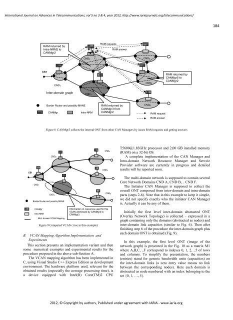
Figure 8 CANMgr2 collects the internal ONT from other CAN Managers by issues RAM requests and getting answers<br />
Border Router and possibly MANE<br />
CANMgr<br />
Intra-NRM<br />
CND2<br />
CND3<br />
Multi-domain VCAN Mapping<br />
CND4<br />
CND5<br />
Information on resources used for this<br />
VCAN addressed by CANMgr2 to<br />
CANMgr3<br />
Figure 9 Computed VCAN ( tree in this example)<br />
CND6<br />
B. VCAN Mapping Algorithm Implementation and<br />
Experiments<br />
This section presents an implementation variant and then<br />
some numerical examples and experimental results for the<br />
procedure proposed in the above sub-Section A.<br />
The VCAN mapping algorithm has been implemented in<br />
C, using Visual Studio C++ Express Edition as development<br />
environment. The hardware platform used, relevant for the<br />
obtained results (especially the average processing time), is<br />
a device equipped with Intel(R) Core(TM)2 CPU<br />
T5600@1.83GHz processor and 2,00 GB installed memory<br />
(RAM) on a 32-bit OS.<br />
A complete implementation of the CAN Manager and<br />
Intra-domain Network Resource Manager and Servcie<br />
Provider software are currently in progress and detailed<br />
results will be reported soon.<br />
The multi-domain network is supposed to contain several<br />
Core Network Domains CND A, CND B, .. CND F.<br />
The Initiator CAN Manager is supposed to collect the<br />
overall ONT composed from inter-domain and intra-domain<br />
parts (steps 2-6). Note that in this example to keep it simple,<br />
we did <strong>no</strong>t specify exactly who the initiator CAN Manager<br />
is. Actually it can be any of them.<br />
Initially the first level inter-domain abstracted ONT<br />
(Overlay Network Topology) is collected – expressed in a<br />
graph containing only the domains (abstracted as <strong>no</strong>des) and<br />
inter-domain link capacities (similar to Fig. 6). Then after<br />
finishing step 6 of the procedure the inter-domain graph plus<br />
each domain ONT is obtained (Fig. 9).<br />
In this example, the first level ONT (image of the<br />
network graph) is presented in the Fig. 10 as a matrix M1<br />
where A,B,C, ..F correspond to indexes 0, 1, 2, ..5 of rows<br />
and columns. To simplify the presentation, the numbers<br />
(entries) stand for generic bandwidth units (capacities) on<br />
the inter-domain links (a zero entry value means <strong>no</strong> link<br />
between the corresponding <strong>no</strong>des). Here each domain is<br />
abstracted as <strong>no</strong>de numbered with an index belonging to the<br />
set {0, 1, …, 5}.<br />
184