rd - 1962 - ENC Conference
rd - 1962 - ENC Conference
rd - 1962 - ENC Conference

Create successful ePaper yourself
Turn your PDF publications into a flip-book with our unique Google optimized e-Paper software.
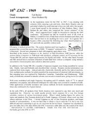
3 <strong>rd</strong> - <strong>1962</strong> Pittsburgh<br />
Chair: David Grant<br />
Local Arrangements: Gus Friedel<br />
“Thi<strong>rd</strong> <strong>Conference</strong> on Experimental Aspects of NMR Spectroscopy”<br />
[T.C.O.E.A.O.N.M.R.S.]<br />
How Sweet It Was! My reflections on the early <strong>ENC</strong> <strong>Conference</strong>s (which were held for a decade<br />
in Pittsburgh) include three dominant memories:<br />
First, the format of the conference was more of a panel discussion than that of a formal<br />
lecture. The speaker’s comments and audience discussion and remarks were merged into<br />
short debates and idea sharing. These sessions, although heated at times, never seemed to<br />
interfere with an expanding camaraderie. The size of the group undoubtedly illuminated the<br />
need for formality.<br />
Second, the meetings solidified a rapidly growing community of NMR spectroscopists into a<br />
cohesive group of friends, unified by the taxing experimental challenges that all faced in<br />
these early days. When one discusses the problems of swinging metal restroom doors on the<br />
other side of the wall from the magnet lab, one knows the field is its initial stages. The<br />
group was small enough that discussion continued often late into night at Samreny’s, the<br />
Ranch, or some other restaurant in the vicinity of Mellon Institute.<br />
My thi<strong>rd</strong> recollection deals with the inclement weather in Pittsburgh during the last few days<br />
of February and first few days of March, typical times for the early meetings of the <strong>ENC</strong>.<br />
To fly out of Pittsburgh always seemed to pose a problem like sleeping on the airport floor<br />
for an early morning delayed flight, etc. Such was the case on Satu<strong>rd</strong>ay, March 2 nd 1961,<br />
the concluding day of the second<br />
conference chaired by George<br />
Slomp. All flights had been<br />
cancelled for the evening of that<br />
day, and I had to be in Columbus<br />
that night. I expressed my<br />
congratulations to George for an<br />
excellent program, and to be<br />
pleasant indicated that I would be<br />
happy to assist in any way<br />
possible to keep the tradition now<br />
started for future years. This<br />
forced a bus trip during the<br />
business session requiring that I<br />
leave around 3-4 PM and travel through West Virginia and into Ohio. There were numerous<br />
delays, but we finally arrived around 10 pm, long ove<strong>rd</strong>ue and fatigued by the o<strong>rd</strong>eal. Upon<br />
my return to Utah the next week I was chagrined to find out the haza<strong>rd</strong> of leaving the<br />
meeting early was to be elected to chair the meeting the following year. Apparently,<br />
everyone wanted the group to continue meeting, but only if someone else would do the<br />
work. Fortunately, Gus Friedel, at the US Bureau of Mines near Pittsburgh, and the<br />
resonators at Mellon Institute provided outstanding support as the arrangements committee,
and many stepped forwa<strong>rd</strong> to chair a variety of sessions and other duties. The vendors aided<br />
with expenses.<br />
For these early meetings, there were no formal abstracts, but many individuals brought printed<br />
hand-out material, often many pages with great detail. For the <strong>1962</strong> conference – with the lengthy<br />
name and abbreviation given above -- these notes, now available in the conference archives on the<br />
web site and the DVD, give a reasonably complete summary of the proceedings. The talks by<br />
James Shoolery on absorption mode 13 C spectroscopy and slave reco<strong>rd</strong>ers stand out to this writer as<br />
truly seminal work of great timeliness in the thi<strong>rd</strong> annual conference. Jim was truly the chemists’<br />
advocate for NMR methods in these early days and his data are typical of his unique signature on<br />
the field.<br />
Equally impressive presentations were also made by other contributors, but space limitations<br />
prevent a detailed review of the 40-50 talks. However, the titles of the eight sessions, each chaired<br />
by an authority in the field, give a good idea of the scope of the conference:<br />
Paul Bender: New Experimental Applications and Techniques<br />
Paul R. Shafer: New Instrumentation<br />
Stan L. Manatt: Spin-Spin Decoupling<br />
Tom Beukelman: Spectrometers of the A-60 Type (Field Frequency Lock)<br />
Wayne Lockhart: Instrument Trouble Shooting<br />
David W. McCall: Relaxation Phenomena and Measurements<br />
Charles W. Wilson, III: Wide Line N.M.R. Instrumentation & Operation<br />
George Slomp: Interpretation, Storing and Cataloguing of High Resolution N.M.R. Spectral Data
8:15 A.M.<br />
9:00 A.M.<br />
9:15 A.M.<br />
I0:30 A.M.<br />
I0:45 A.M.<br />
12: 00 Noon<br />
2:00 P.M.<br />
3:15 P.M.<br />
3:30 P.M.<br />
6:15 P.M.<br />
7:15 P.M.<br />
8:30 A.M.<br />
9:15 A.M.<br />
i0:30 A.M.<br />
i0:45 A.M.<br />
12:O0 Noon<br />
2:00 P.M.<br />
2:00 P.M.<br />
THIRD CONFER<strong>ENC</strong>E ON ~ ASPECTS OF N.M.R. SPEC~COH<br />
TO BE HELD AT THE MELLON INSTITUTE, PIttSBURGH, I~NSYLVANIA<br />
Registration<br />
WelcQme and Oreintation<br />
MARCH 2 and 3, <strong>1962</strong><br />
PROGRAM<br />
FRIDAY - MARCH 2, <strong>1962</strong><br />
ist Session: New Experimental Applications and Techniques<br />
Chairman: Paul Bender, Department of Chemistry, University of<br />
Wisconsin, Mad/son, Wisconsin.<br />
Coffee Break<br />
2rid Session: New Instr~entatlon (Probe Modification and Temperature<br />
Control, etc.)<br />
Chairman: P. R. Shafer, Department of Chemistry, Dartmouth College,<br />
Hanover, New Hampshire.<br />
Lunch<br />
3<strong>rd</strong> Session: Spin-Spin Decoupling<br />
Chairman: S. L. Manatt, Jet Propulsion Laboratory, California<br />
Institute of Technology, Pasadena, California<br />
Coffee Break<br />
4th Session: N.M.R. Spectrometers of the A-60 Type (Field Frequency<br />
Control - Quantitative Measurements, etc.)<br />
Chairman: T. Beukelman, Jackson Laboratories, E. I. du Pont de<br />
Nemours and Company, Inc., Penns Grove, New Jersey.<br />
Social Hour<br />
Dinner<br />
Business Meeting<br />
SATURDAY - MARCH 3, <strong>1962</strong><br />
5th Session: Instrument Trouble Shooting<br />
Chairman: Wayne Lockhart, Varian Associates, 611 Hansen Way,<br />
Palo Alto, California<br />
Coffee Break<br />
6th Session: Relaxation Phenomena and Measurements<br />
Lunch<br />
Chairman: David W. McCall, Bell Telephone Laboratory, Murray Hill,<br />
New Jersey.<br />
7th Session: New Wide Line N.M.R. Instrumentation and Operation<br />
Chairman: Charles W. Wilson, III, Union Carbide Technical<br />
Center, South Charleston, West Virginia<br />
8th Session: Interpretation, Storing and Cataloguing of High Resolution<br />
N.M.R. Spectral Data<br />
Chairman: George Slcmp, The UpJohn Company, 301 Henrietta Street,<br />
Kalamazoo, Michigan
B<br />
o<br />
C 13 NMR Studies Using<br />
the Absorption Mode<br />
J. N. Shoolery, Varian Associates, Palo Alto, California<br />
Due to the long thermal relaxation times associated with C 13 nuclei,<br />
it has been customary to study natural abundance samples with the adiabatic<br />
rapid passage method. This gives a signal proportional to Mo, the static<br />
moment/unit volume, while the absorption mode gives a signal proportional to<br />
~ 7~ for slow passage conditions. Rather considerable line broadening<br />
ccurs as a result of the high r.f. power required for adiabatic conditions<br />
and this not only obscures the smaller splittings due to spin-spin coupling<br />
but makes it difficult to interpret overlapping multiplets.<br />
The need for a large sample is a result of the 1.1% natural abundance<br />
of C 13. Until recently it has not been practical to spin a large sample under<br />
conditions of very high r.f. amplification because the rotation of the sample<br />
introduces a varying coupling between the transmitter and receiver of suffi-<br />
cient magnitude to overload the detector. A static sample results in T 2 be-<br />
ing about two o<strong>rd</strong>ers of magnitude shorter than T I. With modulation techniques<br />
which have been developed for stabilizing the baseline to permit integration<br />
of spectra, spinning a large sample is now practical, since the NMR signal<br />
is now observed as a modulation on the r.f. output of the receiver coil. Less<br />
r.f. gain is required because the signal can be amplified in a subsequent audio<br />
amplifier, and r.f. fluctuations at the spinning frequency can be distinguished<br />
from the modulation frequency through use of a phase sensitive detector.<br />
An instrument operating at 15.085 mc/sec in a magnetic field of 14,092<br />
oersteds was employed in this work. A special receiver coil was constructed<br />
by winding a coil on the inside of a cylindrical glass support with i.d. of<br />
14 mm. Thin-wailed cells were obtained from the Wilmad Glass Company, Buena,<br />
New Jersey, with i.d. of ii mm and o.d. of 12 mm. A plastic spinner obtained<br />
from the same source provided a satisfactory means of rotating the cells at<br />
about 30 r.p.s. A cylindrical teflon plug was made which could be fitted into<br />
the cell at the liquid interface to prevent formation of a vortex. With this<br />
arrangement it was possible, by careful adjustment of the Homogeneity Control<br />
Unit, to achieve an effective T 2 of 2-3 sec., observed by the exponential os-<br />
cillatory decay following the signal from a strong, single C 13 resonance line.<br />
The signal-to-noise situation is made still more tolerable by the fact<br />
that more than adequate resolution is achieved without the necessity of meeting<br />
the slow passage conditions. Under the non-adiabatic rapid passage conditions<br />
actually used, the role of T I in repopulating the lower energy levels is not<br />
as important; i.e., we can use more r.f. power and leave the nuclei in a par-<br />
tially saturated condition, at the expense of some line broadening but with a<br />
gain of signal strength. Sweep rates of about i cps were used for most of
C 13 NMR Studies Using<br />
the Absorption Mode<br />
_<br />
J. N. Shoolery<br />
this work which resulted in spending a small fraction of T 1 in observing<br />
each C 13 resonance line.<br />
A standa<strong>rd</strong> integrator accessory was used which employs 2000 cps field<br />
modulation. Instead of obser*ing the center-band signal as with protons,<br />
the side-band signals were reco<strong>rd</strong>ed. This made possible a much lower index<br />
of modulation. Center-band signals can be suppressed by adjustment of phase,<br />
while second side-band signals are lost in the noise, due to the low modula-<br />
tion index. Thus, no interference is caused by the modulation unless the<br />
interfering signals are 4000 cps (400 ppm) apart.<br />
With this apparatus, previously unresolved spin-spin splittings were<br />
readily observable. Fig. i shows the spectrum ofacetic acid. The C 13 in<br />
the carboxyl group is found to be a quartet with spacing corresponding to<br />
J = 7.5 ! 0.5 cps, due to the protons on the adjacent carbon atom. The di-<br />
rect JCH coupling is 132 cps.<br />
Fig. 2 shows the spectrum of ethanol. The methyl carbon is split into<br />
a quartet with a 125 cps coupling to the attached protons, and less than 2 cps<br />
coupling to the methylene protons. On the other hand, the methylene carbon<br />
shows a 140 cps coupling to its own protons (enhanced by the attachment to oxy-<br />
gen) and a 4.5 + 0.5 cps coupling to the methyl protons. The chemical shift<br />
between the two carbons is 38.5 ppm.<br />
An excellent example of the data obtainable in this way is found in pyri-<br />
dine. Fig. 3 shows the spectrum with the ~ carbons falling at the highest field<br />
value, the y carbon 11.8 ppm to lower field, and the ~ carbons 26.0 ppm to lower<br />
fields. The direct CI3-H couplings are 180, 157, and 160 cps for the 5, ~, and<br />
y carbons respectively. The ~ carbons are coupled to two other protons, prob-<br />
ably the ~ proton and either the ¥ or the other a proton, with coupling constants<br />
of ii.0 and 6.2 cps. The ~ carbon is coupled abort equally to the ~ and ¥ pro-<br />
tons with J = 8.0 cps. Finally, the ¥ carbon is coupled to the ~ protons with<br />
a 5.8 cps coupling constant, and is apparently not coupled to the a protons.<br />
Chemical shift measurements and initial location of the peaks would be<br />
improved by collapse of the spin-spin multiplets to a single line by double ir-<br />
radiation techniques. Since apparatus for this purpose was available, the exper-<br />
iment was tried with a 4 mm sample of methyl acetylene enriched to 50% C 13 in the<br />
methyl position. The spectrum with and without 60 mc irradiation is shown in<br />
Figure 4. In addition to the signal-to-ncise enhancement of 16/3 due to the col-<br />
lapse of the 8-1ine multiplet, there is an additional Overhauser amplitude enhance-<br />
ment of 1.5 due to relaxation of the C 13 nuclei through the proton magnetic mo-<br />
ments. The effect may be greater than 1.5 and could best be measured from the<br />
integral, since the collapse of the multiplet does not appear to be complete at<br />
the power level used.
FIG. 3<br />
FIG. 4<br />
180<br />
i<br />
Jc-oH =11.0 cps<br />
JC.;.C.H= 6.2 cps<br />
I<br />
-26.0 ppm<br />
C ~3 NMR SPECTRUM OF METHYL<br />
ACETYLENE (C~3H3-IC12---C ~2H ) AT<br />
15.085 mc/sec WITH PROTONS<br />
IRRADIATED AT 60 mc/sec.<br />
o<strong>rd</strong>n ry<br />
~--~ ..... :pectrum\<br />
C :~ NMR SPECTRUM OF PYRIDINE<br />
(Natural abundance)<br />
(15.085 mc/sec.)<br />
I<br />
Jc-c-H=SJBcps I =B.Ocps<br />
II<br />
Y ~<br />
I I -H--<br />
-11.8 ppm 0.0<br />
...with irradiation<br />
Jc-~ (cp5)
DARTMOUTH COLLEGE<br />
~EPART.~IEXT OF OHE~ISTR~"<br />
HANOVER • NEW HAMPSHIRE<br />
Insert Construction for Nl~ Probe<br />
io Place the coax fitting and the insert tube (note i) in the jig.<br />
2. Wind uninsulated, oxygen free~ high conductivity copper wire<br />
(OFHC, 30 gauge) around the tube° Space the turns with fine<br />
thread and secure the ends under tension from rubber bands. (note 2)<br />
3. Warm the tube to about 60 ° and apply a very thin layer of epoxy<br />
resin (note 5) so that it flows evenly around wires and thread.<br />
~. Heat briefly (about 2 minutes) at IOO ° until the resin is tacky,<br />
remove the thread and apply a second coat of resin~ using the<br />
minimum amount to get a uniform coating. Bake at iOO ° for<br />
thirty minutes°<br />
~o Bend the free ends of the wire~ slightly separated, down to the<br />
coax fitting9 secure with Scotch Tape~ coat with resin and bake.<br />
6. Trim one lead to just reach the "dimple" depression and solder<br />
with a minimum amount of solder and heat.<br />
7. Remove from the jig, bend the second lead smoothly under the<br />
bottom of the insert to the center, and then do~mo Trim short so<br />
that when the tip of wire is inserted into the pin jack and the<br />
parts are assembled, there is no excess wire and it lies smoothly<br />
in the groove without touching the metal case of the coax plug.<br />
Solder the lead to the pin jack and assemble°<br />
8° Coat the bottom of the insert tube with epoxy resin (note %),<br />
press the tube into the coax plug and place the assembly in the<br />
jig. Remove excess resin to give a smooth joint and bake until<br />
the resin has set°<br />
Note s o<br />
i. Clean the insert tube with trisodium phosphate solution, water,<br />
aqua regis, water and then ammonia, in turn, and bake to dry.<br />
2o For proper balancing, the coil should be tipped very slighly<br />
rather than being exactly perpendicular to the axis of the tube.<br />
The wire can be obtained from various sources, one of which is<br />
Sigmund Cohn~ 12~ S. Columbus~ Mt. Vernon, N.Y.<br />
3. Ciba Araldite Resin 6010 cured with ha<strong>rd</strong>ener Araldite HN-9~I,<br />
available from Do Ho Litter Co.~ Inc., PO Box 247, 30 Lowell<br />
Junction Road, Balla<strong>rd</strong>vale~ Mass.<br />
4. Any commercial resin with a non-metallic loading, such as Hysol<br />
or One-Ton etc. The Ciba resin might work but it is claimed that<br />
the addition of an inert filler improves dimensional stability<br />
over a wide range of temperature change.<br />
8-1-61 Paul R. Shafer
Insert Tube for Variable Temperature N~/:R Probe<br />
!<br />
~cte I ~ . . . .<br />
¢ t<br />
'---> @ %<br />
_ 0<br />
-II Cry.--<br />
I<br />
~J<br />
I<br />
_0/<br />
note 3<br />
io Flat, closed end. Maintain OD to fit into lip of coax fitting.<br />
2. Space three holes at about 120 ° around the tube, each about 2 mm OD.<br />
Maintain tube !D to give clearance for the nylon bearing.<br />
3o Fire polish very lightly.<br />
%. Material: 8 mm OD pyrex tube, standa<strong>rd</strong> wall. Select ID to give<br />
slip fit with the nylon bearing.<br />
Coax Fitting for NNIA Insert. (Not to scale)<br />
[__<br />
I<br />
, / d , ' s<br />
---~ ~qot~ I.<br />
-262/c<br />
n o~e q.<br />
rD o{ r;.:.~, ~v.v~ 6+)<br />
~o~.e 2..<br />
i. Cut off, then face down to length of coax plug on a standa<strong>rd</strong><br />
insert tube less 1 mm. for depth of rim.<br />
2. Cut out faced off end to depth of about 1 mm. Make the ID of the<br />
rim to slip over the end of the insert tube.<br />
3. Shorten the pin jack until it is just flush with the surface when<br />
it is pushed into place.<br />
%o Cut a groove for 30 gauge wire (flush) from the pin jack hole to the<br />
rim, notch the rim, and continue the groove down to one of the<br />
"dimple" depressions on the side of the plug. Cut this portion<br />
of the groove to the depth of the dimple.<br />
8-1-61 Paul R. Shafer
,f,<br />
F.<br />
Construction details for N.,',,:R insert coil winding jig.<br />
£ I~'1' t<br />
i D ,. ?_.i£-<br />
E<br />
£<br />
t<br />
H<br />
L'-i~crf /7, /<br />
"lop Jtc~<br />
~.op Ut~.v~<br />
i. Mount end support A rigidly to bottom plate D.<br />
2. Mount end support B on slide F which moves between guides G-G'.<br />
3. Drill holes C-C' co-linear to fit insert tube (ca 8mm OD). Enlarge<br />
hole C to fit coax plug. Fit each hole with an end plate.<br />
~. Side posts E-E', mounted rigidly to D opposite the coil, serve as<br />
(a) tie points for the coil and (b) terminus points for the<br />
tension springs H-H' which hold the insert assembly in place.<br />
~. Space posts E-E' far enough apart so that a length of wire a' = a<br />
can be secured to each side . Then when the rubber bands are cut<br />
loose the leads will be free of kinks.<br />
6. The scale is about one-half~ the overall length is about i~ cm. and<br />
the dimmensions are not critical. The materigl is wood.<br />
8-1-60 Paul Ro Sharer
O<br />
04<br />
+<br />
gl<br />
Y<br />
O<br />
n<br />
|<br />
I<br />
o4 O<br />
04 -- C) O<br />
O<br />
LO<br />
0 I.u,<br />
_8 w<br />
, , ' - - t H I , ' . _<br />
Y<br />
0<br />
%,.<br />
2<br />
O<br />
co v ~<br />
O<br />
O<br />
0<br />
04 --<br />
i<br />
in<br />
O<br />
0 O~ O4.c<br />
o 1_o<br />
o
t<br />
SLAVE RECORDER FOR AN ~4R SPECTP.OIdETER<br />
James N. Shoolery, Varian Associates, Palo Alto, California, and<br />
Richa<strong>rd</strong> W. Mattoon, Abbott Laboratories= North Chicago, Illinois<br />
Presented at the Thi<strong>rd</strong> <strong>Conference</strong> on Experimental Aspects of NMR Spectro-<br />
scopy, Mellon Institute, Pittsburgh, Pennsyivanias March 2 and 3, <strong>1962</strong><br />
~t is often very useful to have a slave reco<strong>rd</strong>ing reduced in size from<br />
the master NMR spectrum and available simultaneously with it. This<br />
eliminates the delay in cb=aining a reproduction of the master spectrum.<br />
Also, a good slave reco<strong>rd</strong>ing on standa<strong>rd</strong> 8 I/2" x II 'I paper is conveni-<br />
ent as a secondary reco<strong>rd</strong> for reports and for an auxiliary research<br />
file. The master spectrum for the Model A-60 ~[R spectrometer measures<br />
ll" x 26" overall with the graduated chart space 25 cm. Y-axls, 50 + 2 cm.<br />
X-axis (9.8" x 20.~').<br />
METHOD I,L SLAVE X-AX~S TIME SWEEP<br />
In ldethod I. a Moseley X-Y reco<strong>rd</strong>er, Model 3S, using 8 II~' x II" graph<br />
paper (graduated in inches in Figure I only by chance) was covmected<br />
to the A-60. The two AHP/INT OUTPUT terminals on the rear of the A-60<br />
console were connected to the two Y-axls input terminals of the slave<br />
reco<strong>rd</strong>er. The Y-axis gains were set to give appropriate amplitudes.<br />
Each reco<strong>rd</strong>er was cet for its own internal 500-second full X-axis<br />
sweep. The A-60 was adjusted to put the SiMs 4 line on the right-hand<br />
0 of its X-axis (chemical shift). Since this slave reco<strong>rd</strong>er time-<br />
sweeps only to the right, both reco<strong>rd</strong>ers were set on the extreme left<br />
and started simultaneously.<br />
Figure i shows that the slave reco<strong>rd</strong>ing is a practically perfect repro-<br />
ductlon of the masker reco<strong>rd</strong>ing even for the small background ripples.<br />
The strong peak at 60 CPS (I,0 PPI0 is a doublet at highest resolution<br />
(evident here as a slight shoulder) and this is reproduced in the<br />
slave reco<strong>rd</strong>ing. The slave reco<strong>rd</strong>er reached its right-hand limit a<br />
little before the A-60 and so on the slave reco<strong>rd</strong>ing the SIMs 4 line is<br />
to the right of the edge of the graduated portion of the paper. X-dls-<br />
placements in Figure I between corresponding peaks on the master to<br />
those on the slave give a ratio varying between 1.89 and 1.93, averaging<br />
1.91. The disadvantages of Method I. are the inability (I) to sweep<br />
to the leftp (2) to independently set the SIMel. line exactly on the 0<br />
of the slave and keep the two reco<strong>rd</strong>ers so-syn~hronlzed,o,- and (3) to<br />
have the ratio of the two X-axes 2,00 exactly.
-2-<br />
METHOD II. SLAVE X-aXIS SYh~HRONIZED WITH 14ASTER<br />
In Method II. a Moseley X-Y reco<strong>rd</strong>er, Model 2 (II" x 17", larger than<br />
required here), was connected to the A-60 with the Y-axis connection<br />
as above; the X-axls was connected to the center arm of the 1.15 ohm<br />
sweep potentlomzter located underneath the A-60 reco<strong>rd</strong>er, The slave<br />
reco<strong>rd</strong>ing was made on 8 I/T' x ii" paper graduated in millimeters<br />
(18 cm. Y-axls, 25 cm. X-axls). Since the X-Input inpedance of the<br />
slave reco<strong>rd</strong>er is many thousand ohms on the I volt range, no effect is<br />
observed in connecting it to the 1.15 ohm sweep potentiometer. The<br />
X-axis positioning control and the X-axis gain control of the slave<br />
reco<strong>rd</strong>er appear to interact. To put the SIHe 4 llne on the 0 of both<br />
reco<strong>rd</strong>ings and also have the master X-displacements exactly 2.00 times<br />
those on the slave required an Iteratlve procedure of adjusting one<br />
control and then the other. Three adjustments of each control, re-<br />
quiring about one minute, were sufficient to do this. The two recor-<br />
ders then remained perfectly synchronized.<br />
Figure 2 shows again that the slave reco<strong>rd</strong>ing is an excellent duplica-<br />
tion of the master reco<strong>rd</strong>ing, but this time the two SiMe 4 lines are on<br />
the 0 of the X-axes. The master-to-slave X-displacement ratio it Fig-<br />
ure 2 now ranges between 2.00 and 2.04, averaging 2.02, and this aver-<br />
age ratio can be adjusted even closer to 2.00. On the X-scale of the<br />
master 1 mm. is I cycle per second and on the slave it is 2 cycles per<br />
second within II error. Thereby, chemical shifts in cycles per second<br />
may be read directly also on the slave reco<strong>rd</strong>ing from the mm. gradua-<br />
tions. Method II°avoids all three disadvanteges of Method I. listed<br />
above.<br />
For the Method Z. tests acknowledgment is made for the kind coopera-<br />
tion of Dr. R. T. Dillon of G. D. Searle & Co. and the F. L. Moseley<br />
Co., represented by Crossley Associates.
io<br />
"h,<br />
_1_<br />
T<br />
m<br />
]<br />
i<br />
~ =<br />
o<br />
, ~: i I~ :ii : ,: . . . . . . . f~<br />
,:,1!,i : ~ I ~ ,~il ~ ,1:~,; !~<br />
iiiiill ii;iii~ii i ~ ~ ~-'<br />
~'i~I if l - , - ~ i ¸<br />
' I ~ !!i !i~ !I i t ¸i ¸¸'1! ! ~', t i~<br />
i ;i1:!::11:::1~: I:ll :~, ~::: i,: ~ ~, ~ ~<br />
~;:l~!;!;l~:,~I~:~il~ ]i, [ ~ '1'~';-~<br />
,~;~I~:': iiii ~i: :ii~f ii ~i; i!i ~ - ~<br />
.~,":i!!i]~;i"!;;iii~ ..... !!"!!ii!! ;~ E![ii!i"ii!!iiii'i<br />
~o<br />
- -2
--2<br />
u<br />
~L<br />
-f-<br />
,(<br />
• _= o<br />
k<br />
o _o<br />
o _"<br />
±<br />
T<br />
~W!~ ~ - o
@<br />
I<br />
! i<br />
!<br />
i ,-
J<br />
,/<br />
On the Use of Amplitude Modulation in Measuring Large Chemical<br />
Shifts and in Producing Sidebands for Spin Decoupling Experiments.<br />
L. G. Alexakos and C. D. Cornwell<br />
Department of Chemistry, Univsersity Of Wisconsin<br />
Madison, Wisconsin<br />
Two common methods for generation of sidebands used in measurement<br />
of frequency separations in NMR spectra are a) modulation of the field<br />
by injection of an audio voltage in the sweep coils and b) frequency<br />
modulation of the RF generator. The first of these is generally<br />
satisfactory at low audio frequencles~ but fails above about I000 c/s~<br />
probably because of attenu~tlon of the modulating field by eddy currents<br />
in the probe. A further inconvenience associated with this method is the<br />
need for using widely different modulating voltages at different modulation<br />
frequencies on account of the inductive reactance of the modulation coils.<br />
Method (b)~ frequency modulation of the RF generator, may be used at<br />
higher audio frequencies. With this method~ however# an error can arise<br />
if the carrier frequency is shifted by the modulation. If the measurement<br />
is made by placing sidebands on either side of the line 3 this error can<br />
become very serious at higher modulation frequencies 3 since relatively<br />
large frequency deviations are required for the generation of sldebands<br />
of adequate amplitude when the modulation frequency is high. Thus with<br />
the frequency modulation system of the varian ~310C Spectrometer# we have<br />
observed a substantial shift in the position of a fluorine resonance line<br />
as the amplitude of the modulation voltage is changed. The change in<br />
average frequency of the RF generator as measured with a frequency counter<br />
was found to be well over I00 c/s. A similar observation was made with<br />
the ~II spectrometer.<br />
We have employed pure amplitude modulation of the RF generator for<br />
the measurement of splittings over a very wide range of modulation<br />
frequencies~ with excellent results. The circuit arrangements used in<br />
the V4310C and V~311 are shown in Fig. I (a) and (b) respectively. The<br />
modulating voltage is introduced at the grid of a multiplier stage, at<br />
a point well isolated from the ascillator itself.<br />
Sidebands~ generated in this manner show little change in amplitude<br />
as the modulation frequency is changed from 20 c/s to 60 kc/sec at a<br />
constant modulation voltage. (The lower frequency limit could presumably<br />
be reduced by increasing the sizes of the coupling capacitors.) As would<br />
be expected for pure amplitude modulation I no effect is detectable in the<br />
frequency as measured by a counter except for the expected decrease in<br />
apparent frequency observed when the percentage modulation approaches<br />
I00~ at which point some of the cycles are "missed" by the counter.<br />
Frequency spllttings from several hundred cycles to over 40 kc/sec have<br />
been measured with this method with excellent reproducibility. Consistent
-2-<br />
results are obtained even with a large percentage modulation and a very<br />
distorted modulation envelope, since the carrier frequency remains strictly<br />
constant even though the apparent average measured by a counter decreases.
I<br />
v 3o/<br />
L<br />
MoJ. o.o 3p~- _Z_ 0.2 ,~.~i~<br />
VIOl<br />
5 t:~e<br />
L [0~<br />
o os/.~ o.I<br />
~k<br />
,,-,b<br />
ct.,oke<br />
t:<br />
j,,,I ,.-,J. ~FT Rill<br />
FT - F--e ~.~/ "t.l,~o,--,.~L,<br />
.<br />
171,~<br />
~C3o& i~ V3°2<br />
__Z_<br />
c_~, p
SPIN DECOUPLER<br />
by<br />
Daniel D. Elleman and Stanley L. Manatt<br />
Physical Sciences Division<br />
Jet Propulsion Laboratory<br />
California Institute of Technology<br />
Pasadena, California<br />
The spin decoupler which is shown in the figure employs a<br />
phase detector quite similar to that used in the Varian integrator 1.<br />
(i) LeRoy F. Johnson, "Operation of an NMR Integrator System," is<br />
"NMR and EPR Spectroscopy," by Varian Staff and Consultants,<br />
Pergamon Press, 185 (1960).<br />
The IN216 diodes used in the phase detector are a matched<br />
pair and are imbedded in a copper block to maintain them at a constant<br />
temperature. Ten turn pots have also been used in the phase shifter<br />
and audio amplitude section so as to give a little better control in<br />
these settings. Also, 0.022 ~f capacitors have been placed at the<br />
output to the sweep coils to attenuate the modulation. A switch, not<br />
shown in the diagram, has been added so that these capacitors can be<br />
shorted so the full output of the audio amplifier can be placed on the<br />
sweep coils.
A pre-amp has also been added to give some additional gain<br />
at the phase detector. A General Radio Sound Analyzer, Model 1554A,<br />
is placed in front of the pre-amp. The Sound Analyzer acts as a narrow<br />
band filter that can be tuned to pass only the decoupling frequency.<br />
The analyzer has a band pass of approximately 3%.<br />
A set of capacitors has been added across the output reco<strong>rd</strong>er<br />
gain pot. These capacitors act as a filter and can be set to give any<br />
desired time constant so as to reduce high frequency noise at the output.<br />
One must remember to by-pass the RC filter network on the V4311 spectro-<br />
meter@ If this is not done, the audio signal to the phase detector is<br />
attenuated. The most convenient method of by-passing the filter network<br />
is to set the spectrometer on WL ~ mode of operation.<br />
With this decoupler we have been able to decouple spin systems<br />
that have coupling constants greater than 50 cps and chemical shifts over<br />
9000 cps. The smallest frequency that we have set the decoupler is 40 cps.<br />
At frequencies smaller than 40 cps, the signal to noise becomes very bad.<br />
Additional details of the operation of the spin decoupler are given in<br />
a paper which will appear about April 15 2.<br />
(2) D. D. Elleman and S. L. Manatt, J. Chem. Phys. (in press).
• 3<br />
Samples of proton 3'4 and fluorine 5 of spectra obtained with<br />
(3) S. L. Manatt and D. D. Elleman, J. Am, Chem. Soc.,8_~., 4095 (1961).<br />
(4) S. L. )kmatt and D. D. Elleman, J. Am. Chem. Soc., (in press).<br />
(5) D. D. Elleman and S. L. Manatt, J. Chem. Phys., (in press).<br />
this spectrometer can be found in other publications 6.<br />
(6) All recent Jet Propulsion Laborator~ Research Summaries.
-- rl t~<br />
-J > u~ w<br />
O O LL<br />
o ~ o _~ ~, ~, o<br />
o w '~" ~ o o ¢~<br />
'O. ~ ~ (nm to<br />
T L[L[<br />
;~ / °- ! o~a tao _z<br />
ioT -o<br />
n'c~ . . , Q-<br />
~o o , o~ ~o<br />
~;I ~ i -~18<br />
- _1 "i I, o<br />
0 ~<br />
• - "-'" • 111. ; O O. ~'<br />
o T--~'-"-"~ o ~<br />
~- ,,, I o o ,~ o ~I -<br />
fir" •<br />
zi:<br />
t~<br />
~o<br />
I-<br />
od<br />
El(/)<br />
~0<br />
,<br />
rl-
~<br />
T<br />
rt~<br />
m<br />
Cu~<br />
~4<br />
A<br />
m<br />
1 m<br />
V<br />
m<br />
c~<br />
rt~<br />
I<br />
C~
W<br />
Z<br />
X<br />
W<br />
I<br />
q<br />
W<br />
Z<br />
W<br />
N<br />
Z<br />
W<br />
I<br />
I
A<br />
Q~<br />
Z o<br />
X<br />
I<br />
0<br />
o<br />
wQ<br />
f<br />
m<br />
A<br />
T<br />
V<br />
rr~<br />
!<br />
r~<br />
c~<br />
I<br />
V<br />
r~<br />
m<br />
c~<br />
r~<br />
m<br />
~J
Me-C<br />
Me-C--~-<br />
I<br />
CH<br />
-*--- CH<br />
I<br />
z,' 2 = 35.809880 Mc/s<br />
Not Decoupled<br />
8.502508 Mc/s Cl3(H a) SPECTRA OF<br />
H3C CH 3<br />
CH 3<br />
CH 3<br />
MESITYLENE
CH-2,6<br />
tJ<br />
1<br />
8.502508 Mc/s CI3(H I) SPECTRA<br />
OF N,N-DIMETHYL-p-TOLUID|NE<br />
?"2 = 33.812600 Mc/s<br />
92 :33.813300 Mc/s<br />
H3C\ /CH 3<br />
N<br />
CH 3<br />
~'2:33.810280 Mc/s<br />
N-CH 3<br />
-,-- CH 3
J<br />
CH-3,5--~<br />
C-I<br />
V<br />
J<br />
8.502508 Mc/s CaS(H I) SPECTRA<br />
OF N,N-DIM ETHYL-p-TOLUIDI NE<br />
HsC\NzCH 3<br />
6 2<br />
5 3<br />
CH 3<br />
~z = 33.809785 Mc/s<br />
z/2 = 33.809080 Mc/s<br />
CH-3,5 A Not Decoupled<br />
C-I ,/'1 CH-2,6<br />
' m /"/ ' ' N-CH3
2 . . . . . . .<br />
--CH<br />
Not Decoupled<br />
I<br />
~CH<br />
I<br />
.......... _C = - COH<br />
8.502508 Mc/,~ CI3(H I) SPECTRA<br />
OF 3-METHYL-I- PE NTYN- 3-OL<br />
-----C-OH<br />
CH 3<br />
!<br />
CH3-. CH2-C, -C = CH<br />
OH<br />
I I<br />
I<br />
~2:33.811538 Mc/s<br />
~, : :33.811016 Mc/s<br />
C'H3CO<br />
I<br />
l I<br />
CH2 _.<br />
J I_ _
8.502508 Mc/s CI3(H I)<br />
SPECTRA OF<br />
5 -METHYL-I- PENTYN- 3-OL<br />
CH 3<br />
CHECH2-C-C= CH<br />
I<br />
OH<br />
; CH 2<br />
z/2= 33.812700 Mc/s<br />
z/2= 35.812950 Mc/s C*H~ C-O<br />
z/2:33.813620 Mc/s<br />
.4-- C~H3-CH2
o b c<br />
CI3(H I) SPECTRA OF n- HEXANE<br />
CH3CHzCi-<br />
c b a<br />
~_ C 2 CH2 C H 3<br />
a b c<br />
AT 8.502508 Mc/s<br />
a) 33.812880 Mc/s<br />
b) 33.813220 Mc/s<br />
c) 33.813500 Mc/s<br />
33.813200 Mc/s
Sn(CH3) 4<br />
J<br />
f<br />
Sn 119 Snil9(H I)
~<br />
pm----'m I<br />
0<br />
A<br />
rt~<br />
I<br />
V<br />
C~J<br />
I C~<br />
C~J<br />
7-<br />
C<br />
J<br />
4)<br />
A<br />
C~<br />
m<br />
U_<br />
V<br />
m<br />
T<br />
m<br />
I
(lh<br />
I<br />
I.L<br />
I<br />
-r<br />
CO<br />
r,-.<br />
z<br />
0<br />
I<br />
I--<br />
f~<br />
m<br />
I<br />
_I<br />
0<br />
N<br />
-1-<br />
"1"<br />
I N<br />
-r"<br />
L)<br />
I<br />
0 I<br />
"1-<br />
U<br />
II<br />
U_<br />
U<br />
I<br />
m<br />
0<br />
-r<br />
0<br />
I<br />
"l-<br />
u<br />
I<br />
L)<br />
0<br />
I<br />
I I I I I I<br />
I I I I I I I<br />
O O 0 0 0 O 0<br />
O 0 O 0 0 0 0<br />
O 0 O O 0 0 0<br />
0:<br />
E<br />
0<br />
0 0<br />
0<br />
0<br />
0<br />
:0<br />
_o o<br />
o_<br />
0<br />
-0<br />
¢-'1<br />
-°o
q<br />
f<br />
i/,,t<br />
!<br />
!<br />
I I I I !<br />
-'-::=,.._<br />
I I I I I<br />
co ~. ~ eu 0<br />
c~ o d d<br />
u Z<br />
'~" 0<br />
o I--<br />
a "a<br />
.C}<br />
- ~ -~<br />
(.f)<br />
>-<br />
rn .c_<br />
o<br />
-- 0 Vl ,,<br />
-.lb. I ~ N<br />
~ I I<br />
-ru_<br />
m<br />
l<br />
1<br />
u<br />
1<br />
l<br />
l<br />
N<br />
b.l<br />
0 CO<br />
-- I~<br />
,,~<br />
O~ ...I<br />
0 ...I<br />
co 0<br />
W W ~<br />
~ 0 u<br />
Z 0<br />
Z ~ ~<br />
g'rS;<br />
I--<br />
I- l<br />
I<br />
u_<br />
0
D<br />
I I I ! I I I I<br />
O<br />
-- ~) O o..I<br />
_ m I~ o -<br />
a<br />
n.,l~<br />
n'- rm<br />
LI.I<br />
n,'i--<br />
O~<br />
U._ _.1<br />
Z O<br />
o O<br />
~>-<br />
rr-<br />
_1 W<br />
oO<br />
W<br />
Nn-"<br />
"!- Ii<br />
_ ~9 r..D --<br />
E E<br />
-- O<br />
O<br />
I I I I I I I I<br />
O O O O O O O O<br />
O O O O O O O O<br />
O O O O O O O O<br />
~D ~1" 0J O GO ~ ~1" oJ<br />
~9<br />
o<br />
O<br />
U<br />
O<br />
QD<br />
O<br />
O<br />
lad<br />
O~
U.<br />
0 •<br />
C<br />
0<br />
0<br />
J J J<br />
0<br />
J<br />
//<br />
%%<br />
/o<br />
/<br />
W<br />
Z<br />
W bJ<br />
I N<br />
Z<br />
W<br />
0<br />
Z<br />
Z<br />
~u Z<br />
wO<br />
Z<br />
W<br />
O~ ~<br />
n-<br />
• U8<br />
~. l ~.<br />
~ ~.~<br />
~ g<br />
j J I<br />
0<br />
--0<br />
I',-<br />
0<br />
--0<br />
_8<br />
t~<br />
-0<br />
0<br />
--0 ro<br />
0<br />
ro<br />
V')
,:z:<br />
O<br />
I--I<br />
I<br />
• L.<br />
l<br />
I<br />
0<br />
.<br />
il<br />
! J ! !<br />
0 0 0 0<br />
(~=) ~0z~ ~v~a<br />
0<br />
I<br />
0<br />
I<br />
...Q<br />
0<br />
0)<br />
,rl<br />
IE
.°<br />
I<br />
u<br />
O'/<br />
!<br />
H<br />
O<br />
I.-4<br />
0 0<br />
III<br />
0<br />
0<br />
r.t<br />
II<br />
, !<br />
0<br />
b--<br />
0 0<br />
r-I<br />
0<br />
0<br />
0<br />
0<br />
0<br />
r-i<br />
E
I00<br />
50<br />
0<br />
CORRECTED INTEGRAL AMPLITUDE (LOW SATURATION)<br />
r = I0 @/s 2<br />
(H20, TIT2~, 25 see.2)<br />
1oo ~/2<br />
i I J , I J<br />
0.5<br />
H I (mllllgauss)
E<br />
r 2r .<br />
Johnson, 4th Annual Varlan NMR Workshop (1960)
• T~-"<br />
• * ' * i T " •<br />
t<br />
i i<br />
T<br />
I<br />
,'~t i~'<br />
, i<br />
. . . . . I<br />
.-2-..~. i . . ~ ..... "<br />
AL: A~C~,~,¢Y: : : i i : :<br />
• • * ~ . .<br />
• * t<br />
.... r ~<br />
; . . . . i<br />
• . • [ • !<br />
. . . i<br />
• • • • I & l * •<br />
.... i:"::' i ' "<br />
' . . 1 . . .<br />
' " " T<br />
' ' ~ ' i " . . " . . . .<br />
~_<br />
- t ......... ... ,.m ....<br />
• 0;0~ . . . . . . . "~ ~"<br />
.... i... '-[::-<br />
Io~ .it+ .i<br />
..l~:, ~ ,~.<br />
. . . . l . . . .<br />
. . . . . . . .<br />
4
0<br />
2<br />
4<br />
8<br />
10<br />
ERROR IN rNTEGI~L RATIO (H20 SAMPLES)<br />
(TIT2)~/(TIT2)b ~Io4<br />
i • i • I * • ~ i I i i • . I i * • * |<br />
0.5 1.0 1.5 2.0<br />
H I (milligauss)
~<br />
0<br />
E~<br />
~D<br />
Z<br />
0<br />
0<br />
r~<br />
r 4 .<br />
1<br />
i<br />
t<br />
• °<br />
• ° . ,<br />
°<br />
. . . . . . . o . . . . . . . .<br />
, I<br />
i<br />
T
©<br />
+<br />
I<br />
!<br />
J<br />
J<br />
l<br />
H<br />
~.......-.......-~<br />
T<br />
.<br />
bD o<br />
bD<br />
J<br />
o<br />
!<br />
o<br />
0<br />
r-~ -P<br />
O ,'d ,.C<br />
~ ~c~ ~<br />
0<br />
~+~ ~<br />
o ~<br />
m ~<br />
ID o fl)<br />
N~<br />
o<br />
i1) .~<br />
.cl,O<br />
4.~ ~<br />
.r-t<br />
o m<br />
%<br />
i11 i1)<br />
E-~<br />
d<br />
hO<br />
°r-.I<br />
-0<br />
-0<br />
i1)<br />
~!i-~.
©<br />
l<br />
L<br />
o<br />
_!<br />
-Z<br />
i<br />
l<br />
oJ<br />
gl<br />
.r-t<br />
r-i<br />
o<br />
0~<br />
,¢1<br />
ID<br />
CH<br />
.~<br />
,-el<br />
0<br />
0<br />
4-~<br />
m<br />
0<br />
ko<br />
I<br />
,--t<br />
4.~<br />
a3
NMR PULSE SYSTEM<br />
by<br />
S. Meiboom<br />
Bell Telephone Laboratories, Incorporated<br />
Murray Hill, New Jersey<br />
The pulse system consists of one Tektronix type<br />
162 waveform generator and three type 161 pulse generators,<br />
interconnected as shown in Fig. i. A type 160 A power<br />
supply and a type 360 indicator, used for checking pulse<br />
shapes, complete the system. The pulses A, B and C are<br />
fed into a Varian V 4311RF-unit, modified as indicated in<br />
• . "B" the trans-<br />
Figs 2 and 3 "A" is the receiver gate,<br />
mitter gate and "C" the 90 ° RF phase shift gate (So Meiboom<br />
and D. Gill, Rev. Sc. Instr. 29, 688 (1958)).<br />
operation:<br />
The pulse system has three different modes of<br />
i) "Time division" high resolution. The 162<br />
runs "recurrent" at about i000 cps. It triggers the 161<br />
B unit, which delivers pulses of about 20 ~sec length to<br />
the transmitter gate. The rising edge of these pulses<br />
triggers the 161A unit, which delivers negative pulses<br />
of about 30 ~sec to the receiver gate. In this mode unit<br />
161C is inoperative.<br />
2) T 2 measuremdnts. In this mode unit 162 is on<br />
"gated" and operates only when the normally closed switch S<br />
is pressed. Pressing S delivers a voltage step to 16i C<br />
and triggers a single 90 ° pulse. Unit 161B is triggered
- 2 -<br />
at the center of the 162 sawtooth and delivers 180 ° pulses<br />
at the 162 repetition rate as long as S remains open. Unit<br />
161A is triggered by the rising edge of the B output and<br />
gates the receiver.<br />
3) T I measurements. Unit 162 runs in "recurrent"<br />
mode at a low rate (period more than four times T 1 to be<br />
measured). Unit 161B is triggered by return of sawtooth,<br />
unit 161C by sawtooth after about 1/5 of period. Unit<br />
161A is again unchanged. Repetition rate is adjusted for<br />
zero signal on 90 ° pulse.<br />
pulse generators.<br />
The following modifications have been made in the<br />
a) In unit 161B the leads to the grids of V 5<br />
have been interchanged. The unit now delivers a negative<br />
gate rather than a negative pulse (i.e. the output is<br />
normally negative and goes to zero during the pulse).<br />
Also, the 90 ° pulse delivered by 161C is mixed with the<br />
180 ° pulse of 161B by connecting the cathode of V 4 B in<br />
the C-unit to the cathode of V 5 in the B-unit (R 33 of<br />
the C-unit is disconnected).<br />
b) In o<strong>rd</strong>er to make for easy switching between<br />
different operating modes, the trigger circuits of the<br />
pulse units have been modified as indicated in Fig. 4.<br />
The two trigger modes ("negative sawtooth" and "positive<br />
pulse") have been provided with individual input connectors<br />
and individual bias potentiometers.
-3-<br />
c) The range of all units has been increased by<br />
a factor of lO, to provide for very long relaxation times.<br />
In unit 162 an additional position with a I0 ~F capacitor<br />
has been provided on SW 3. Similarly 1 ~F capacitors have<br />
been added to SW 2 of the 161 units.
~w<br />
0<br />
o~<br />
W<br />
&.<br />
I,-<br />
oP:,-~<br />
z~<br />
ILl<br />
03~<br />
00..~<br />
n::3 Q_<br />
+<br />
41<br />
0<br />
e'l<br />
m<br />
k.9<br />
W<br />
"J~O<br />
Ik<br />
I,.IJ t.._<br />
I-- -,~<br />
~oO<br />
~°<br />
LO W<br />
I.~ I,-<br />
_J', 0<br />
n<br />
IJ'<br />
0<br />
o<br />
~U<br />
vm<br />
L,j<br />
Z<br />
W<br />
r~<br />
ILl<br />
U3<br />
._...1<br />
13_.<br />
Lt_<br />
0<br />
Z<br />
0<br />
I--<br />
U<br />
LL~<br />
Z<br />
0<br />
n,,'<br />
F.--<br />
Z<br />
I I<br />
b_
0 0<br />
~(---t,, I >-~<br />
il<br />
I I<br />
~-~0<br />
I ,(<br />
~LJ n,,<br />
v<br />
~°<br />
~<br />
d<br />
L<br />
k<br />
'NAA,<br />
mO<br />
'VNA,--<br />
--M Ul--<br />
- 11,<br />
AAA<br />
o,~ <<br />
~0 W<br />
><br />
0<br />
or)<br />
O<br />
m<br />
m<br />
LU<br />
Od<br />
oct)<br />
w<br />
0-- 0 ¢~ ~U')<br />
VV~ u.. ~ I1.,.<br />
- OE)<br />
II,<br />
d<br />
.a_
.~ c:>-~l, I( :<br />
: ~,..L,, ~<br />
U~II - - ,<br />
• ~ 1 -<br />
-o u"'-~. _<br />
~ ~oo<br />
I~. Ill --0"11<br />
I1~-- I<br />
-- ' - I( i<br />
O0 o,~<br />
t~. ~ 0<br />
o~. e,- o .~<br />
J<br />
@"1<br />
_-0_.1 ~ ~-[. gJ- oOJ- @°<br />
hk<br />
"<br />
oo ~g<br />
W<br />
eo<br />
ZCl<br />
_0<br />
I<br />
~o_<br />
Q<br />
0<br />
m<br />
~° i °~<br />
j<br />
0<br />
I - ,(<br />
U~<br />
I I<br />
I<br />
-z Qo<br />
~__o<br />
w<br />
Z<br />
I<br />
0<br />
I,<br />
I,I<br />
m<br />
a<br />
W<br />
m<br />
I,<br />
I<br />
0<br />
~f<br />
i<br />
I,
°t o .9o<br />
•<br />
TM r<br />
0 i.i.l"<br />
Ul<br />
rn<br />
0<br />
v ~ LL
SPIN-ECHO MEASUREMENT OF NMR RELAXATION TIMES<br />
by<br />
R. S. Codrington<br />
Ridgefield Instrument Group<br />
Ridgefield, Connecticut<br />
In steady-state NMR studies the parameters of primary importance,<br />
apart from the signal amplitude, are the linewidth of the resonance<br />
and the frequency at which the resonance occurs in a given magnetic<br />
field. It is wel~known, however, that in o<strong>rd</strong>er to obtain meaning-<br />
ful steady-state NMR spectra, the modulation frequency and sweep rate<br />
must meet certain conditions determined by the relaxation times T 1<br />
and T 2. These relaxation times, respectively called the spin-lattice<br />
and spin-spin times are defined by the Bloch equations. 1 In Fig. i,<br />
possible methods of measuring these times with steady-state equip-<br />
ment are shown. For both measurements, it is assumed that the steady-<br />
state apparatus has been set to observe the peak of the absorption<br />
curve. Inherent in the Bloch formulation is the assumption that when<br />
a sample is placed in a steady-state apparatus, the signal will in-<br />
crease exponentially with a characteristic time T I. The assumption<br />
is also made that if the r.f. driving voltage is suddenly shut off<br />
while a signal is being observed, the signal will decay exponentially<br />
with a characteristic time T2. The simple assumptions of Bloch are<br />
valid for NMR spectra of most liquids but they do not always apply to<br />
the NMR spectra of complex liquids, semi-solids and solids in which<br />
T2 decays with nonexponential character may be observed. The tech-<br />
niques of measuring T1 and T 2 described in Fig. 1 would only be use-<br />
ful for a restricted range of relaxation times. A direct measure-<br />
ment of T 1 and T 2 over a much wider range can be achieved with spin-<br />
echo techniques which are based on the same principles as the tech-<br />
niques of Fig. 1 but which utilize pulsed rather than steady-state<br />
apparatus.<br />
A great deal of information about the internal structure of materials<br />
can be obtained from a detailed analysis of NMR spectra. Such<br />
analysis usually includes studies of the linewidth or second moment<br />
versus temperature and the behavior of T1 versus temperature. Al-<br />
though in principle the steady-state apparatus can provide all the<br />
information required for a complete NMR analysis, it is often found<br />
to be easier and quicker to complement the information provided by<br />
the steady-state apparatus with spin-echo data. An example of the<br />
use of spin-echo in aiding the interpretation of steady-state NMR<br />
signals is given in Fig. 2. In this figure the derivative absorp-<br />
tion curves from two polyurethane samples are compared with the T 2<br />
decay curves. In the steady-state presentation, the signal from
polyurethane A is obviously narrower than the signal obtained from<br />
polyurethane B. However, it is noted that the signal in the wings of<br />
resonance A is greater than the signal in the wings of B. When the<br />
T 2 decays of the signals are examined, the situation becomes a little<br />
clearer. The straight line decay curve for polymer B indicates that<br />
the line shape of the steady-state signal should be pure Lorentzian.<br />
The faster decay of the signal from polymer A indicates that most of<br />
the protons in the sample are in a broad line phase. The narrow line<br />
observed for polymer A in the derivative steady-state presentation is<br />
actually only derived from about 20~ of the protons in the polymer.<br />
In this paper, a pulse programmer is described which is useful in<br />
carrying out a variety of spin-echo measurements. The unit may be<br />
used with r.f. pulse apparatus discussed in papers by Schwartz ~,<br />
Buchta et al 3, Meiboom and Gill 4, and Blume 5, and has particular<br />
value when used with the integrating circuits described by Holcomb<br />
and Norberg 6, and Blume7 Before discussing the programmer, some of<br />
the terms used in the spin-echo technique will be introduced briefly.<br />
In Fig. 3, a 90 ° pulse is defined. The term 90 ° arises from the fact<br />
that after the moment M 0 has been established in the d.c. magnetic<br />
field direction, an H 1 field is applied for a time just long enough<br />
to rotate the moment through 90 ° , i.e., to a position along the Y<br />
axis. If the HI field is intense enough, the moment will reach the Y<br />
axis unattenuated and in this position will induce a signal in a pick-<br />
up coil which will decay at an exponential rate characterized by T 2.<br />
If T2 is large, however, i.e., if the natural width of the resonance<br />
is less than the homogeneity of the magnet over the sample, the decay<br />
of the signal following a 90 ° pulse is determined by the magnet in-<br />
homogeneity.<br />
In Fig. 4, the echo technique, originally developed by Hahn 8, is des-<br />
cribed which allows the full free precession decay to be monitored in<br />
the presence of an inhomogeneous field. The sequence described by<br />
the four illustrations is as follows: a 90 ° pulse rocks the three<br />
magnetic moments into the direction of the Y axis. After awhile the<br />
moments get out of phase due to the inhomogeneity of the magnetic<br />
field. A 180 ° pulse, twice the length of a 90 ° pulse, is then<br />
applied to the system which swings the dephased moments from the<br />
positive Y to the negative Y direction. Moments which were lagging<br />
in phase are now leading in phase and vice versa. In a time equal to<br />
the time between the 90 ° and 180 ° pulses, the moments will come back<br />
into phase and form an echo signal.<br />
In Fig. 5a, the complete sequence is shown with the peak amplitude<br />
of the echo signal for all positions of the 180 ° pulse indicated by<br />
the dotted line. In liquids, where the diffusion constant is quite<br />
-2-
large, the echo signal amplitude falls off much more rapidly than<br />
would be the case if the decay was purely determined by T 2. The<br />
equation derived by Carr and Purcell for the echo signal decay is<br />
given in the figure. Carr and Purcell 9 were able to show that by<br />
applying a large number of 180 ° pulses following the 90 ° pulse, the<br />
echo signal amplitude could be made to follow the real T 2 decay curve.<br />
A Carr-Purcell sequence is given in Fig. 5b.<br />
Spin-echo apparatus is particularly useful in providing an easy and<br />
quick method of determining T I. For the T 1 measurement, a 180 ° pulse<br />
is first applied which rotates the moment into the negative Z direc-<br />
tion as shown in Fig. 6. If the apparatus is correctly tuned, no free<br />
precession signal should be observed following this 180 ° pulse. After<br />
a time Z~., a 90 ° pulse is applied and a free precession signal is<br />
observed which in the figure we assume to be detected with a phase-<br />
sensitive detector. As the time ~between the 180 ° and 90 ° pulses is<br />
increased, the amplitude of the free precession signal is observed to<br />
go to zero and then increase in the positive direction. The time qT 0<br />
for which the free precession signal is zero is related to T 1 by the<br />
expression T 1 = i~44 ~0-<br />
In Fig. 7, an apparatus which might be used in the observation of<br />
spin-echo signals is described in block form. The apparatus consists<br />
of a pulse programmer which provides pulses for the 90 ° and 180 ° gates<br />
at the times desired. The 90 ° and 180 ° gates are univibrators or one-<br />
shots which can be varied to produce the correct 90 ° and 180 ° gate<br />
widths. The two gates from the univibrators are combined in an ampli-<br />
fier and are used to control an r.f. gate connecting the r.f. oscil-<br />
lator with the sample coil assembly. The signals following the r.f.<br />
pulses are amplified and observed with a wide-band oscilloscope which<br />
can be triggered at the desired times with pulses from the programmer.<br />
In Fig. 8, a detailed block diagram of a spin-echo pulse programmer<br />
is given which can be assembled from transistorized computer logic.<br />
The timing of all pulses in the unit is controlled by a i00 Kc.<br />
crystal oscillator which drives a 6-place counter. Any time interval<br />
from i0 ~seconds to i0 seconds in units of i0 pseconds may be selected<br />
with a 6-place preset giving rise to signal G" The selected time T<br />
is the basic timing unit of the pulse programmer. Another 6-place<br />
preset (i) is used to select a time interval less than T which deter-<br />
mines the position of the oscilloscope trigger. Signal~drives a<br />
flip-flop, output Qof which is used to drive a latching pulse cir-<br />
cuit which produces the 90 ° pulse. The latching circuit has a<br />
characteristic that it lets the first pulse of Qthrough but will<br />
not let any subsequent pulses through until it is reset with reset<br />
voltage B. Signal Qon the other side of the flip-flop is used to<br />
(* T. J. Calvert and R. S. Codrington: To be published)<br />
--3--
drive both a 4-place counter and a circuit producing the 180 ° pulses.<br />
The number of 180 ° pulses desired can be selected with the 4-place<br />
preset (3). This preset drives a flip-flop which shuts off the 180 °<br />
pulses until it is reset by reset B. The 4-place preset (2) is used<br />
to select the number of periods T after which the whole program<br />
sequence will repeat itself. A manual button and selector switch are<br />
provided so that the sequence will only repeat when the manual button<br />
is pushed. The 4-place preset (i) is used to select the number of<br />
the 90 ° or 180 ° pulse position with reference to which the scope<br />
trigger will be positioned. The switch showing 90 ° and 180 ° positions<br />
is used to select this pulse reference. A reversing switch is also<br />
provided so that the 90 ° and 180 ° gates may be interchanged. The gate<br />
widths are derived from univibrators which have both a coarse and fine<br />
control.<br />
In Fig. 9, the pulse and gate sequences at the various positions in<br />
the logic circuit are shown. For this particular sequence, the pro-<br />
grammer has been set to reset on every ten basic timing units T. A<br />
normal Carr-Purcell sequence has been selected with one 90 ° gate<br />
followed by three 180 ° gates° The scope trigger has been selected to<br />
be in advance of the thi<strong>rd</strong> 90 ° pulse which actually does not occur but<br />
is indicated by the dotted line. The letters preceding each sequence<br />
refer to the positions in the block diagram of Fig. 8 at which the<br />
respective voltages may be observed.<br />
In Fig. 10, an actual oscilloscope display of a Carr-Purcell sequence<br />
is shown. In Fig. ii, the same sequence is presented except that the<br />
scope sweep amplitude has been set to display a single echo width.<br />
The scope trigger advance was referenced to the 90 ° pulse position<br />
and a value selected in terms of the clock period which would allow<br />
the complete echo to be displayed. Succeeding echoes in the Carr-<br />
Purcell sequence were then selected with the 4-place preset (i) up<br />
to a maximum of the number selected on 4-place preset (3) in the<br />
block diagram of Fig. 8.<br />
In addition to its use in displaying details of the echo signals,<br />
the flexibility of a programmer in providing a pulse at any position<br />
in the spin-echo sequence makes it very useful when used in conjunc-<br />
tion with integrating circuits for the observation of weak signals.<br />
-4-
References<br />
I. F. Bloch, Phys. Rev. 7_~0, 460 (1946).<br />
2. J. Schwartz, R.S.I. 2__88, 780 (Oct. 1957).<br />
3. J. C. Buchta, H. S. Gutowsky and D. E. Woessner, R.S.I. 2_99, 55,<br />
(Jan. 1958).<br />
4. S. Meiboom and D. Gill, R.S.I. 2_99, 688 (Aug. 1958).<br />
5. R. J. Blume, R.S.I. 3_22, 554 (May, 1961).<br />
6. D. F. Holcomb and R. E. Norberg, Phys. Rev. 9_~8, 1074 (1955).<br />
7. R. J. Blume, R.S.I. 3_~2, 1016 (Sept. 1961).<br />
8. E. L. Hahn, Phys. Rev. 8_~0, 580 (1950).<br />
9. H. Y. Carr and E. M. Purcell, Phys. Rev. 9_~4, 630 (1954).<br />
-5-
MAGNETIC RESONANCE TIMES<br />
OF RELAXATION EFFECTS.<br />
Spin- Letiice Time T~<br />
Signal<br />
O T o T Ime<br />
Sample Is placed In the Ha field<br />
at time t • O<br />
Spin- Spin Time T2<br />
Signal ~ ,<br />
O T 2 Time ---.-<br />
The R.F. field Is turned off<br />
time t • O<br />
Fiqure 1 - Steady-State Observations of T 1 and T 2<br />
Effects<br />
"S<br />
,'//<br />
J I I I<br />
.ioe<br />
I<br />
at<br />
M I Q m ~ •<br />
\//<br />
.7-"<br />
I I ! I<br />
THE 90 ° PULSE<br />
FigurQ 2 - Comparison of the Steady-SLate and Free Prec~aaion Signals<br />
Fro~ Two Polyurethanes<br />
i<br />
|<br />
[]<br />
w<br />
90 ° PuIN<br />
Fiqure 3 - The Free Precession Signal FolloWing a 90 ° Pulse<br />
IN ~LLlUCOMOS<br />
Tlml
THE SPIN-ECHO SEQU<strong>ENC</strong>F<br />
3.<br />
M~<br />
il<br />
Y<br />
/ \\<br />
0 1 2<br />
90 ° Pulse<br />
180 =' Pulse Echo<br />
Figure 4 - Simplified Illustration of the Echo Sequence<br />
MEASUREMENT<br />
SINGLE<br />
~0 °<br />
i'---to<br />
ECHO SEQU<strong>ENC</strong>E<br />
(2) CARR- PURCELL SEQU<strong>ENC</strong>E<br />
180a 2 ~._ 5~<br />
• --t ¢: S e.x -f t T "tH U.& /<br />
2<br />
4.<br />
~-'=: ~ "- o Pl-%- I"-T'fnT " f<br />
1- t s Time<br />
Echo<br />
90 ° 180 ° 180 ° 180 °<br />
_ I_ 2"E-I-~ Time<br />
Figure 5 - Single and Multiple Echo Sequences Used in the<br />
Measurement of T 2<br />
Y<br />
0<br />
X
180 ° oJO°<br />
Po .s'~.--<br />
Ne9.~ /<br />
~ '~o<br />
MEASUREMENT<br />
-------M<br />
T,<br />
.I<br />
Null<br />
I'l<br />
It<br />
I t<br />
! !<br />
11<br />
| I ~<br />
i<br />
I , i<br />
!<br />
, Time.<br />
I<br />
I<br />
I<br />
I !<br />
I<br />
!<br />
I<br />
I .<br />
Figure 6 - The. Spin-Echo Method of Measuring T I<br />
SPIN-ECHO APPARATUS<br />
I RK OSCILLATOR<br />
4<br />
AMPLIFIER<br />
90" GATE<br />
180" GATE<br />
PULSE<br />
GENERATOR<br />
Figure 7 - A Block Diagram of a Spin-Echo Apparatus<br />
AMPLIFIER<br />
~OSCILLOSCOPE l
,~P//,/ EcHo Lo61c<br />
ioo Kcl<br />
'Osc. I<br />
t<br />
i l ~ .R[IiCT A<br />
~ J liSZT B ~ o<br />
@<br />
®<br />
©<br />
®<br />
9O'<br />
I<br />
,J<br />
m<br />
~--- i l~ ~,-,~>. o-~+.~<br />
= ~,___Js/<br />
' i<br />
T B<br />
o<br />
J I<br />
--'- ~1 ~"-DC~ ~''~"<br />
Figure 8 - A Pulse and Gate Generator Useful for Spin-Echo Measurements<br />
0 I 7.<br />
J<br />
® I<br />
® I<br />
® ®111 FI<br />
T.'.,c (Y*,~ 7"<br />
3 • S 6 7 8 9<br />
I I 1 1 1 1 1 1 1<br />
I I<br />
H H<br />
I<br />
I<br />
L_f<br />
Rose4 8<br />
i<br />
I<br />
0 1 Z 3<br />
I I I !<br />
Figure 9 - voltage Pulses and Gates Observed at the Indicated<br />
Points in Figure 8<br />
i<br />
I L<br />
I<br />
I<br />
n H
Figure i0 - An oscilloscope Presentation of the Carr-Purcell Sequence<br />
Figure ii - A Multiple E:[posure of the Sequence in Figure ~O with<br />
Only the Echo Signals Displayed
Thi<strong>rd</strong> <strong>Conference</strong> on Experimental Aspects of NMR Spectroscopy<br />
Mellon Institute, Pittsburgh, Pa.<br />
Program of 7th Session: Broadline N-M-R Instrumentation & Operation<br />
Satu<strong>rd</strong>ay, March 3, <strong>1962</strong>,-~90-P.M.<br />
i¢!<br />
(i) "Introductory Remarks" (5 Minutes)<br />
Chas. W. Wilson, III<br />
Union Carbide Technical Center, So. Charleston, W. Va.<br />
(2) "Knight Shifts Observed at Low Temperatures in Crystalline Organic<br />
Free Radicals" (i0 Minutes)<br />
M. E.Anderson<br />
Physics Dept., North Texas State Univ., Denton, Texas<br />
(3) "Amplitude Calibration and Sample Preparation Work on Metals"<br />
(i0 Minutes)<br />
T. J. Rowland<br />
Dept. of Metallurgy, Univ. of Illinois, Urbana, Ill.<br />
(4) "Use of Varian V-3521 Integrator Unit with Broadline NMR" (i0 Minutes)<br />
Harmon Brown<br />
Varian Associates, Palo Alto, Calif.<br />
(5) "A Simple R-F Phase Detector for NMR Spectrometers" (15 Minutes)<br />
T. J. Flautt<br />
Proctor & Gamble, Miami Valley Labs, Cincinnati, Ohio<br />
(6) "Spectrometer Calibration, Sample Preparation, Operational Techniques,<br />
and New Parameters Describing Mobility in Broadline Polymer NMR<br />
Spectroscopy" (30 Minutes)<br />
W. O. Statton<br />
Carothers Research Lab, DuPont Experimental Station,<br />
Wilmington, Delaware<br />
(7) "TWL Probe Insert Assembly Modifications for Varian V-4340 Variable<br />
Temperature Accessory" (i0 Minutes)<br />
R. H. Elsken<br />
Western Utilization Research & Development Division,<br />
Albany, California<br />
(8) "A Versatile Cryostat for Magnetic Susceptibility, Anisotropy, and<br />
Broadline NMR" (25 Minutes)<br />
L. N. Mulay<br />
Chemistry Dept.,Univ. of Cincinnati, Ohio<br />
(9) Discussion of all papers.
A SIMPLE RF PHASE DETECTOR FOR NMR SPECTROMETERS<br />
Abstract<br />
A phase detector system which can be easily adapted to bridge or<br />
crossed coil NMR spectrometers is described. Modifications to the NMR<br />
spectrometer include addition of a constant impedance attenuator for<br />
control ~ the probe excitation voltage, a leakage control system<br />
independent of probe balance, and a differential dc amplifier to cancel<br />
changes in the leakage from spurious modulation of the transmitter<br />
power.<br />
Copies of the circuits directly applicable for a V4310 transmitter/<br />
receiver unit are available at the address below.<br />
T. J. Flautt<br />
The Procter & Gamble Company<br />
Miami Valley Laboratories<br />
P. O. Box 39175<br />
Cincinnati 39, Ohio
o<br />
a<br />
~J<br />
~ L<br />
-- O<br />
IW a<br />
C~J<br />
a~<br />
N<br />
N<br />
0<br />
T ° •<br />
H<br />
N<br />
U<br />
t~<br />
.7<br />
Ld<br />
['q<br />
c~J<br />
a.<br />
0 c<br />
t~ qCt.<br />
._1<br />
o<br />
m<br />
,1-1<br />
.r4<br />
.I-4<br />
0<br />
~J
om<br />
e~<br />
E<br />
3<br />
O<br />
o~<br />
°~<br />
Q.<br />
E<br />
U-<br />
4- [<br />
~<br />
m<br />
m I I<br />
m<br />
II o<br />
Z - -<br />
uj t ~<br />
._<br />
t<br />
t<br />
~- i[_<br />
° -t: I<br />
9<br />
o<br />
9<br />
r 1<br />
t jl I<br />
I<br />
t_._ ~ ~ J<br />
"-G)<br />
E~<br />
.J<br />
_J<br />
~ m<br />
E~<br />
o _J<br />
g<br />
v~ g.<br />
g(<br />
m<br />
g<br />
> a:<br />
4~ H<br />
(.I<br />
,r4<br />
U<br />
0<br />
0J<br />
Ill
~<br />
iiilliillillil lit: i I I I I ; i illll II II1~ i J<br />
O~<br />
r~<br />
(..)7<br />
IXl U-I<br />
n," I--"<br />
n~<br />
W<br />
6-<br />
Or)<br />
I---<br />
~J~ilill II Iill i I I i i i it I1 I II i I II I<br />
nr<br />
2<br />
.<br />
n,-<br />
w<br />
ix_<br />
w<br />
b<br />
w<br />
m<br />
0<br />
, iJ|jii Jl b i JXbllbli~|l~ IJJJ jJ IJiiiiiJ ~ ~<br />
ii i inil,]l J I1111 I~*lkll '*HlJllJ~,<br />
J<br />
~w<br />
n~_l<br />
woL<br />
Li,J<br />
D<br />
Ci::<br />
0<br />
(,.)<br />
I.I.J<br />
n-<br />
W<br />
w<br />
w<br />
n~<br />
N<br />
,'-I<br />
llO<br />
4,1<br />
C)<br />
4,)<br />
.r-I<br />
II<br />
ill
L' ;~:', "~,',"-'~-, b~P~bV£.~e ~, .
i¢o )?t
"T~L PROBE INSERT ASSEMBLY MODIFICATIONS FOR VARIAN V-4340 VARIABLE<br />
TEMPERATURE ACCESSORY"<br />
R. H. Elsken<br />
Western Regional Research Laboratory, l_/ Albany, California<br />
ABSTRACT<br />
In our wide-line NMRwork, we need to obtain spectra of solids prepared<br />
in sealed containers. For convenience of handling, these sealed con-<br />
tainers should also be the NMR sample tubes.<br />
We have modified extensively the ~.KLprobe insert for the VarianModel<br />
V-4340 Variable Temperature NMR Probe Accessory to accept sealed samples<br />
and, in t~e process, have also increased the filling factor by approxi-<br />
mately h.<br />
In brief, the supplied combination dewar probe insert and sample holders<br />
were disca<strong>rd</strong>ed, and techniques suggested by S. Brownstein (Can. J. Chem.,<br />
B7, 1119, 1939) and Paul Shafer (Mellon NMR Letters, #30, April 1961)<br />
w--~re followed to obtain a compatible system. As shown in the attached<br />
illustration, a two-component dewar and coil insert replaces the Varian<br />
dewar probe insert, and a 9 x 30 mm shell vial replaces the Varian sam-<br />
ple holder. The sample tube assembly is designed to minimize vibration<br />
with high gas flow rates.<br />
In operation, tank nitrogen flows down between the walls of the coil<br />
insert and dewar insert, through holes in the lower section of the coil<br />
insert, up past the sample tube, and out the upper end of the coil insert<br />
tubing. We have used this system primarily for low temperature work.<br />
Average stability is + 0.5 ° C when tank nitrogen flows through a con-<br />
stant flow regulator and copper coil -- liquid nitrogen type heat ex-<br />
changer. Maximum flow rate is approximately 16 liters per minute for<br />
-195 ° C sample temperature.<br />
~/A laboratory of the Western Utilization Research and Development<br />
Division, Agric itural Research Service, U. S. Department of Agriculture.<br />
Reference to a company or product by name does not imply approval or recam-<br />
mendation of the product by the Department of Agriculture to the exclusion<br />
of others which may also be suitable.
F<br />
Z- 3 MM TUBE<br />
,.,, PROJECTS THRU<br />
,: ~!<br />
HOUSING<br />
' '~;":~~HOLD DOW-'~-~-N<br />
JMODIFIEO<br />
TWL VARIABLE TEMPERATURE<br />
" : 2 ~ ' f f<br />
, :,~.~ ~,RIAN_/<br />
;..~,~:~.. DEWAR INSERT<br />
,:~,:~,,;:,'~ :" ~MATCHING CAP<br />
_J ASSEMBLY~<br />
TC LEADS<br />
ADAPTER RING<br />
.3 MM O.[).~<br />
GLASS TUBING INSERT HOLDER<br />
(TEFLON)"<br />
~[ CORK SEAI ~<br />
Ox30 MM<br />
SHELL VIAL<br />
q<br />
GLASS ROD<br />
ION SHELL VIAL<br />
:OIL INSERT<br />
TC LEADS<br />
SNUG FIT ON<br />
3 MM TUBING|<br />
PROBE ADAPTER<br />
HOUSING<br />
NITROGEN<br />
m m~m 90<br />
)EWAR INSERT<br />
A<br />
EXIT NITROGEN<br />
i COIL INSERT 121) mm<br />
DETAILS<br />
I '<br />
TEFLON BNC<br />
SPACER CONNECTOR<br />
t<br />
II mm<br />
Iq mm<br />
BOTTOM<br />
INSERT SEAL<br />
(TEFLON) "'"~ ~:~t-~ mm<br />
~ UG FIT ON 'LL___:J--v-<br />
C01L INSERT
Thi<strong>rd</strong> Annual <strong>Conference</strong> on the Experimental Aspects of N-~-R<br />
Spectroscopy Session on Broadline N-M-R Operation and<br />
Instrum6n ration<br />
L. N. Mulay<br />
Magnetochemistry Laboratory, Department of Chemistry<br />
University of Cincinnati, Cincinnati 21, Ohio<br />
Abstract of Paper<br />
A Versatile Cryostat for Magnetic Susceptibility, Anisotr~py<br />
Broad Line N.M.R.<br />
A versatile cryostat for magnetic susceptibility, anistropy<br />
and Broad-line N.M.R. work has been constructed. It utilises<br />
the Dewar vessels with ground-joints at the lower stem as described<br />
previously by the author (Rev.Sci. Instrum. 28, 279,1957). The<br />
principle used for maintaining a given temperature is different<br />
from that described in this paper. The volume enclosing the<br />
sample is heated electrically with a non-inductive coil. This<br />
is surrounded by liquid nitrogen through appropriate glass-<br />
wool insulation. The particular design permits uniform tempera-<br />
tures over as large a distance as 15 cm. which is particularly<br />
useful for the Gouy technique, which uses long sample tubes. It<br />
may be noted that the older technique of simultaneous heating<br />
and cooling of a metal block, surrounding thc sample produces<br />
appreciable heat gradient over such a long distance.<br />
Using liquid nitrogen, temperatures between -196 ° to 25°0<br />
(Room Temperature) are easily obtained, with a minimum loss at<br />
the high temperatures. However, for economy in the use of liquid<br />
nitrogen above -80°0 one may use dry-ice acetone. (This interferes<br />
with proton magnetic resonance studies. Hence, in this case one<br />
may use carbon-tetrachloride and dry-ice mixture for obtaining<br />
temperatures well below room temperature.) With no coolant,<br />
temperatures as high as 250°C may be obtained easily. In this<br />
range no heat is allowed to leak to the pole faces of the magnet,<br />
which remain protected at+all times. It has been possible to maintain<br />
temperatures within-I °c without any special regulating<br />
devices However, by u<br />
sing ele<br />
-~<br />
ironic<br />
.<br />
circuts,<br />
A<br />
it<br />
of<br />
is<br />
advantaged<br />
possible<br />
of<br />
to maintain temperatures within O.I°C number<br />
this cryostat will be discussed. The information is scheduled to<br />
appear shortly in the literature.
A.<br />
B.<br />
GS : jmw<br />
2127162<br />
T.C.O.E.A. 0. N.M.R.S.<br />
8th Session: March 3, <strong>1962</strong>, 2:00 P.M.<br />
Catalog of NMR Spectral Data<br />
1. G. Slomp: IBM Coding of Shift Data (5 min. ).<br />
2. LeRoy Johnson: The Varian Shift Catalog (20 min. ).<br />
3. Ernst Lustig: Proposal for an Indexed Timely NMR Bibliography<br />
(5 min. ). Discussion of Proposal (10 min. ).<br />
Spectral Analysis<br />
1. Aksel Bothner-By: Introduction and Discussion of Various<br />
Computer Techniques (35 min. ).<br />
2. Ernst Lustig: Comments on Swalens 8-Spin Program for IBM-7090<br />
(5 min. ).<br />
3. Dan Elleman: Comments on Their Results and on the Use of Spin<br />
Decoupler to Determine Signs of Coupling Constants (15 min. ).<br />
4. J. Baldeschwieler: Comments on Their Program, Analysis of Double-<br />
Resonance Spectra~ Higher Spins and Larger Shifts (15 min. ).<br />
5. Other Comments and Discussion (i0 rain. ).
_ _ . y~...-.'.:<br />
NUMBER I NUMBER<br />
ioo o0,D',o~oo o oooooo oooooo oo~ O000OO00000000<br />
!11111111111 II0"11011~11 I1<br />
! 2222J222~ 2222~". 22D': 22222222<br />
13333133333333333333333333<br />
l 4~' 441444444444444(]'.4444444<br />
~5s55ts555550,5~s0 55550"5555<br />
;0".666166666666 G 6666(]' 666666<br />
'777717777777[]' 777~" 77777777<br />
~ 88[[ 818888888888~" 888D" 88680'<br />
J 999919[]' 99~' 990" 9999999[]" 9990"<br />
2 3 4 516 7 O 3 tO tl [21314151611 1019 2~ 2122 23 24 25<br />
IOM 027626<br />
,01701~ 4!<br />
NMR<br />
MU~BER N~<br />
~oorio<br />
123456<br />
I~IIII<br />
2222112<br />
333333<br />
444444<br />
55555<br />
6[;6666<br />
77J777<br />
8888110<br />
9999~9<br />
1 ~ ~ 4 ~ ¢<br />
W~ ~CIUE~"~CY" DATA<br />
uv,os ;B~ .,.Is<br />
1111111111111<br />
!2222222222222<br />
33333333333333<br />
14444444444444<br />
55555555555555<br />
$6666666666666<br />
77777777"777777<br />
98888888888888<br />
~9999999999999<br />
r~2~ 3t ~34~3637~40<br />
oooonoo oooooooooooooooo<br />
15 t6 II 19 20 21 22 73 24 ~ ~ ~r'/ ~ 79 30 3~ ~L1 34 ~L5 "t~ ]7 'uz<br />
II1~1 Illl lJ]!11111111111 i<br />
2222['l~2222]]J] 22222222222212<br />
333333~3333333333333333313<br />
4444444.q44444444~444444414<br />
5555~]f25555~5555555555555~5<br />
so~<br />
o<br />
~n<br />
m ~1~1<br />
011 O--'L~o00000000<br />
ii<br />
111111111111<br />
22 ]21222222222<br />
33 331333333333<br />
44 441444444444<br />
55 551555555555<br />
66 661666666666<br />
77 771777777777<br />
88 001888888888<br />
99 99]999999999<br />
42 4: M 45]46 47 48 43 ~ ~1 ~ ~<br />
666666666661"16666[1666666616 66666666666666666666666666666666666666666<br />
777771177770'777777777777717<br />
80 e 61]n 80 8[I 0116 8 8 8 8 6 6 8 8 6 s 816 88888886888888888888888888888888888888888<br />
99999999991] 999999999999919<br />
I.<br />
~ I ~: 13 IJ 19 ~ 21 ~ ;~ 2Z 25 25 .~12~ 2.3 7~ 31 .~2 ~ ~ ~ "zS ~7 2Zl23 4,.1 41<br />
,:H~,<br />
I<br />
000000000000000000000000000000000000000000<br />
~ 404l 42 43 ~ 4~ 4fi 41 48 49 ~ 5| ~ ~ ~ ~ ~ 57 ~ ~ ~§1 ~ Q ~ ~ ~ 61 ~ U ~ 11 ~ 1J 14 75 ~ 77 18 ~ ~<br />
111111111111111111111111111111111111111111<br />
22222222222222222222222222222222222222222<br />
33333333333333333333333333333333333333333<br />
44444444444444444444444444444444444444444<br />
55555555555555555555555555555555555555555<br />
777777777.77777777777777777777777777777777<br />
9999999999999999999999~999999999999999999
MAIN GROUPS<br />
FUNCTIONAL GROUPS<br />
1. R---CH 3 a. "--CH 3<br />
2. R--CH2--R' b. ---CH2--<br />
I<br />
3. R--CH--R" c. ---CH--<br />
I I<br />
R' d. --C--<br />
4. R--CH=N--R' I<br />
5. R---CH=CHz<br />
6. H~C__C~ R'<br />
R I ~H<br />
e. --CI<br />
f, --F<br />
cJ. --Br<br />
h. --H<br />
H~ c C ~H<br />
7. = i. --I<br />
R ~ ~R'<br />
i- --c<br />
R~ ~H<br />
8. R~C'--C~H k. --C ~O<br />
9. R'~'C=cIR" I. --C=<br />
R I ~H I<br />
10. R--C~CH m. --N--<br />
11.<br />
110<br />
R---C~H<br />
n. --N~<br />
o. --O--or--> 0<br />
1 2. R~//O p. --OH<br />
~OH<br />
q. --O---C~ °<br />
13. R--OH<br />
14. Phenyl<br />
15. Pyridyl<br />
16. Furanyl<br />
r. --NOz<br />
S. --S~<br />
t. --C=C--<br />
17. Pyrryl u. ~ N<br />
18. Thiophenyl v. Phenyl<br />
19. Misc. aromatic w. Aromatic ring junction<br />
20. R'~NH<br />
x. Misc. aromatic<br />
R ~ y. Thiophenyl<br />
21. H on other atoms z. Misc. atom
I<br />
2<br />
301,302 !<br />
. . . . . . ;. ~. . . . . . . . . ; . + , , . . . . - t + + - * * ~ ÷-J *++~ . . . . . . *-+++ - "-;-$*' ' , . . . . . 1 1 + . + . , . F . . . . . . + - f - , - * . . . . . . t ....<br />
. . . . . . . . . . . . . . TT:i:-~T, "Ti .-~nTII~-~-TT. --7 T~ :. .... ~ i, IL +T-T:I -T-<br />
..... = = ...... = ...... =<br />
. . . . . . . . . . + . . . . . . . . . +. + + . . . . .<br />
. . . . . . . . . . . . . . . . . . . . . . . . . . . . . . . . . . . . . . . . . . . . . . . . . . . . . ~ ...... I1" "-+f ........ T-,Ji" " : I-L'.LLL~+E.]L_~_]_::-L _--.<br />
-~ .... 1 .................. +-tT+ITT 7''T+tTi t-+TTT ilL]_ - - _T. ;]:,. -L$- -r. :.$~t____iL:--.. -- --.<br />
:----L--Z--~--.~.+--$.LL --" .'LL.;L::+;;.++ ;-i;.--ii.'.+ ;U .... ' . . . . . . +.l-+.- ...................<br />
, , I , , , , i , , , , I . . . . , . . . . I . . . . i . . . . I , , , , J , , , L I L L * i . . . . I . . . . i , , , , I . . . . i . . . . I . . . . I . . . . i , , ,<br />
8.0 7.0 6.0 5.0 4.0 3.0 2.0 1.0 0 PPM<br />
301<br />
I - met hyl -4- (2-pyridyl) piperidine -<br />
CF~I-~eN20 ~ 4-corboxylic ocid methyl ester<br />
II (b)<br />
(f) [/.~C -- 0 M e<br />
~N"<br />
I<br />
(a) Me ~ss,~.~..,,s<br />
Sweep offset: ~,D_ ppm a ~ e J~6-4~_<br />
Freq. response: __Leps b__3..~_9 f J,5_4<br />
Sweep time: __5.0_0_ sec c ~.J_4__ g __.'7~..O]g~.<br />
Spec. amp: __1.2,5__ d 7.34 h<br />
i<br />
302<br />
• ,,,,===, Procoine<br />
C,~HmN202<br />
(f) (g)<br />
(b) (o)<br />
H/~.~H i01 (e) (c) / Hz--CH~,<br />
(d) HzN'-- ~ ~-- C-- O-- C H2--CH~-N \<br />
H~-~-~H CH2"-CH 3<br />
(f) (g) (b) (o)<br />
3 ~ ~11; N :,~ F ;11 &<br />
Sweep offset:~-- ppm a ~ e ~ 3 _ L<br />
Freq. response: _1__ cps b 2.G 2 f ~6..6_5__<br />
Sweep time: 2 5 0 _ sec c ?..8.2___ cj 7. 8 3<br />
Spec. amp: _ _ 1 6 _ _ d 4.13 h _ _<br />
I ' ~ I T ? I I T I f I I I I I ' ' ' ' ' ' ' ' ' I<br />
• ,6o; "-TT ".:, : ~'-4&o - ~ 3oo . . . . . . . zoo . . . . . . oo . . . . . 9cPs I<br />
2~) '* . . . . + . . . . . . . . . * . . . . . . . - *'~- . . . . . . . . . . . . # I<br />
leo + • . . . . • + . . . . . . . . . ' . . . . . . . . . . . . . . . . . . . . . . . . . . . . . . .<br />
..... E-', _ - ..... T ........................................................... ['T]<br />
................... .'---~ : _--7. T -T-T-T- -.~. .... : - -7- T -777_-7 ..... T --T-- T ]- . .....<br />
5 7L]2i!+[:i{ +21]] : ! :[ 2[ ]2:i:2ii712[i i 2211 iT2 i:? 2172[ i ..........<br />
. . . . . __ . . . . . .;L . ..... ":-i:;.:i -~ +-2-:2.2.T .... T " : TTI- " 2T-.?-<br />
8,0 7.0 6.0 S.0 4~ 3.0 2.0 hO 0 PPM<br />
I
IOOO<br />
5OO<br />
ZSO<br />
303, 304<br />
zOO<br />
50<br />
400<br />
, , I , , , , I , , , , t . , , ,, , ~ , ~, , , I<br />
8.0 7.0 6.0 5.0<br />
303<br />
Ci4H,BrO<br />
p-phenyl phenocetyl bromide<br />
(b) (c)<br />
H H<br />
H H<br />
(c) (c)<br />
C. (el<br />
\CH 2-<br />
S',veep offset:~ppm a~.4_5__ e _ _ __<br />
Freq. response:_2__cps b__7_._7__0__ I _ _ _<br />
Sweep time: __250_ sec c_8.0_7 _ _ g _ _ _<br />
Spec. amp: __ 16 _ d _ _ h_ _<br />
I000<br />
, . . i . . . . i , . . r I . . . . i , . t . . . . f . . . . 1 •<br />
Br<br />
300 200 I0O o cPS<br />
4.0 3,0 2.0 1.0 0 PPM<br />
304<br />
Ci4HliNO 5<br />
Flindersomine<br />
(e) (o)<br />
{b) H OMe (d)<br />
o" "y "N" "o" "H<br />
(c) HzC -- 0 (f)<br />
S. c_., .~'-_-~t __ --_ _ ~ ~.28Dr_4.~0 . 7.2 8__<br />
F, ] ~ !~tnse:_2_ r,:~ ~.28~L4._4.0 _7.62<br />
S. ':ep t,me: __ 250_ ~,,,: - _6.08 _<br />
Sp~c ~ m p : 32 .J~,_Q_5~ , l<br />
500 400 300 200 I O0 0 CPS<br />
25O<br />
I00<br />
50<br />
8.0 7.0 6.0 5.0 4.0 30 Z,O 1.0 !<br />
PPM
0<br />
=,<br />
o<br />
0<br />
v<br />
C-<br />
-;.~<br />
= " .5 ~ • ~.o<br />
-r3 ~J ~J<br />
-~' - ~ " ~o<br />
• °.1~ o<br />
.~ .~ .~ '~,<br />
Jg~<br />
- _ 9 ~<br />
,- # _ ~ ~<br />
- .:~.~<br />
: "~ ~ . ~<br />
N e =<br />
_- ~ - ~.g<br />
=~ -: "_'Z 3 3<br />
.<br />
0 ~ ~<br />
o<br />
G"-~<br />
CM<br />
o .~ o ~<br />
. . . .<br />
= "~ :" .'3 -o"<br />
~:3-~ ~.<br />
=°?~:~<br />
~,<br />
:~25<br />
=<br />
• o<br />
3<br />
=: = 5<br />
0 =<br />
• ,..,<br />
L,<br />
o<br />
.-2,<br />
o<br />
~.~<br />
-=<br />
d ~<br />
= ~ ~ ~ .~-~_~ o~= ~_-=--<br />
- ~ . . ~ . . ~o ~ _~<br />
-~ ~ ~--~o= ~ = ~<br />
~-: - ~ o=: : --~ o - "<br />
_=<br />
- :, ~J ,--I =<br />
o
_<br />
o<br />
.,--:.<br />
,o<br />
..3<br />
- o<br />
,,3 ,~ --.j<br />
.~ ~ o~ ~ o ?~ ~_- ~ ~ -<br />
--~. c-~ ~ . :~ ~ ~ o o o-~ ~'-°~.~-~-,o ~ -~=<br />
.~.~ ~ - ~ ~ o L- -~ o o ~'~ ~ ~'~'-'~ ~ ' ~ ~ ~'~ I ~ ~<br />
.~ _ ~.. ~ :.> ~ ~ ..j "° ~ 0 ~'c-~-~ ~ :~-'- >' ~'~ ~ I ~ ..~<br />
g<br />
~ -~ ~ - °°<br />
o- -~- -~ ~.7.. "~'~'~: uL'~'-'=~ ~<br />
-... ~.~.~:" ,~=:~, , ~ __~.~~'C~':. = ,~ , ~, ,<br />
3
0<br />
14<br />
e',<br />
v<br />
L<br />
0<br />
~=,<br />
('V e'~ U..<br />
,~" ~=~ 0 ~<br />
-~ ~ ~. ~ o ~<br />
o<br />
i-I ~.T 0 ~0 c'~<br />
c'~l .,,0 ~ cO -,4" oo E-.<br />
~',,,oo', ~ * ~ o~ o ~ ~o • a- o ,,--~<br />
,-~ o 0 0 r: c= ~,-,-.~<br />
.,,=i : 0 ==<br />
xO ,_~<br />
"= .~'= d-~ - • • -N,.T<br />
< < .:: .= .:: < ~ = ~ = = = = : =~=o<br />
0<br />
-a =<br />
0 0 r--t ~<br />
r..<br />
..H<br />
=., :j<br />
o~ .~<br />
• ,~ 0 t.<br />
o o -~<br />
C<br />
e..' :J 0<br />
r-.4 ~ ~ ~ o .~ .<br />
,--i ~,.~ o 0<br />
A<br />
0<br />
P.<br />
0<br />
o<br />
cJ<br />
0 ~.<br />
c~O ",4" :==~0 OOc~ r..:. O0<br />
• -- - - ¢,3~ "<br />
o _- - m
ANALYSIS OF HIGH-.RESOLUTION<br />
NMR SPECTRA BY THE ITERATIVE METHODS<br />
by<br />
S. L. Manatt and D. D. Elleman<br />
Physical Sciences Division<br />
Jet Propulsion Laboratory<br />
California Institute of Technology<br />
Pasadena, California<br />
In this handout explicit expressions are given for the pertur-<br />
bation of the energies levels of the ABC and A2B 2 NMR systems as derived<br />
from the perturbation treatment of Hoffman 1~2 for the analysis of high-<br />
i. R. A. Hoffman and S. Gronowitz, Arkiv Kemi l_~, 45 (1999).<br />
2. R. A. Hoffman, J. Chem. Phys. 32, 1296 (1960).<br />
resolution spectra. From the energy levels it is possible to obtain the<br />
perturbation expressions for all the transitions.<br />
tonian into<br />
This perturbation method starts by decomposing the NMR-Hsmil-<br />
°<br />
H = H(°)+H (I)<br />
where = H ( tA)~ ~ 9 • • ? ~ ~) • • °• ) is the approximate<br />
Hamiltonian derived from a first guess of the NMR parameters. Ways of<br />
obtaining this first guess are well known. If the ~2~ and ~j of<br />
the guess are good approxlmations to the quantities ~£ and ~[~ then<br />
H (°) nearly equals H, and H (I) may be treated as a perturbation. By<br />
transposing H (O) we get:<br />
H - H (1).
First-o<strong>rd</strong>er perturbation theory gives for the energy level number ~ !,<br />
L ~ . Thus the first-o<strong>rd</strong>er corrections<br />
to the transitions energies are given by the differences of the form<br />
•<br />
Below the results for the ABC system~it is hoped~are given in<br />
sufficient detail to be understandable. The results for the ABC and<br />
A2B 2 systems were derived by us sometime ago, but they have not been<br />
exhaustively checked for algebraic errors. We present them here for what<br />
they are worth to the practicing NMR spectroscopist. We have also<br />
obtained the perturbation expressions for the transitions of the ABC and<br />
A2~ systems which are easily derivable from the energy level perturbations<br />
given here. We have similar results for the ABX, A2X2J ABC B and ABX 3<br />
systems. We hope to make this work generally available soon either as a<br />
JPL report or external publication.<br />
2
T~ A 5 C S yst:'~<br />
)<br />
State ~.~a q, s P1atr~ Eie~e~%<br />
A~c<br />
I0,.= oI, ~(~<br />
Z<br />
Z<br />
30,, _± +i _<br />
H**- ~.(-%+%+~,~) ~.(Y^~-T~O&,.)<br />
"Z ~<br />
2 o,,_ I~,(;<br />
Z<br />
"3&i<br />
-- (~~<br />
~. ..<br />
H7.4 = -~T~ -'Tac<br />
,~.- -~ ~-~ H~.~ = -k &~<br />
: |
]'h ~s iTh~s<br />
II<br />
is &cc~f,t~sh~_J. by ±~e ¢i~enwct~-<br />
Cii<br />
¢"¢z Co~, C~<br />
l..J<br />
C-~5 C~,o~, C.,,,_ 7
•<br />
a.
~! 0 V,,' W e._. ~ "&.Ve..<br />
H m _ H -H °<br />
e, am pl e camSiaee<br />
= c;~ (.~ I,-~°1~)~ - C43<br />
"~ o._ u o t o "<br />
X<br />
%*%-~- ~(%-r, io)-'- '~ ~°
C o l i e c~t , n ~ ' -t_ e ~- ,',-,'-, o ~ ~ In ~x ~, .,<br />
H Ol - ~ r-. z . z z<br />
-c.~]L%-<br />
~E- , z<br />
~F.C2 C z _7.<br />
(..<br />
{.,.<br />
E! "<br />
-tl~c<br />
~ --~ c~ ~ %., ~e + ..~c~ a %~ ~, ( ~qc,,).<br />
~"t, ~ •<br />
w~e)-c 4C _ ~ . .-z -z<br />
e_~; ~)re 5S i eva<br />
I<br />
Z<br />
• --- j5
C-" -"~ ~ ~ ." - ~e ~-~ -'~ ~3 "-~ ~ ~- •<br />
~ ~, .~-4- .,. '~ ÷ .~, I ~ % .% +<br />
'~ 4- --t- .j .._, ~ ~ ~,,t: .~ ~'~ R ,4:. :~ 9<br />
..~ ~ I.~ < .~ .~ ~ ,< ---, r-:. :~ < ~" ~ "-:', ,~<br />
.2 -4- "=. ."' ,,3 "J- • ~ •, ~ ~"" .~ ~-<br />
~' ,.0 '~ t~
S z<br />
IS I<br />
'ZS~<br />
ISo<br />
"35o<br />
clS~<br />
IS<br />
-'I<br />
2~_i<br />
It~ I<br />
I~. o<br />
I& -I<br />
?--o,, -I<br />
N :<br />
T^~+~-^~<br />
AA~<br />
o~A o(o{<br />
~ ~-~ ¢~-~,~I<br />
/"h~<br />
, . ~(~,~)<br />
I<br />
AT. Bz<br />
_ l H,,- -~I~<br />
14 .z~ = - £i ~<br />
H ---cu-<br />
N~- -~<br />
14-I~ = 0<br />
H -- i<br />
qc I -- --~t~<br />
,. --iN<br />
Ii--<br />
H~= i~,-~ ~,~M<br />
bl ~,E = 0<br />
I<br />
~N<br />
M-:r,A-~ ~A_~o =<br />
_i<br />
H¢-I=--Iw
t4,t<br />
l'i' Z. z . I"lg,.-j<br />
I'1~,. t kt~,s-H,s.. ~. i4~<br />
1~7'fl- H"7~ H-,-.//= H-77 H<br />
II Hi~.<br />
all2. I ~1"~.2 ./.<br />
GT~ C,-/~. 7L, C.7 7<br />
mhe~e ~e $~e<br />
"He¢~j4~<br />
cq~ C~q<br />
,(-:-; y ~;~ e m ~ e_t-. :<br />
I-lot< ~<br />
~1 i('l~i, z<br />
~...Z i('i~ 2.. 2<br />
~f_ %,
I !<br />
(t ~ He°If = .-~<br />
~ The A z~3 z S'×st.e.~<br />
i " "7- "7. •<br />
I~% i,~'l ~%) --_-~:,4Cc,~.~)~ ~ + c,.,c....c._c _, ~<br />
• C%,t<br />
C~i ~) I'~%') = - ( clcc~ ) au, +[cu% + c:.~q. ~-k(c~.+c~_)]a~, +<br />
[C~4.c~. ~ i- %.~Cc. C c~c~...~ ) a~ - c~. 7- a<br />
(,~;i .~'I,~) = -(~ _c?,a~ ~ ~[c~c.~q~q
THIRD CO~."FER<strong>ENC</strong>E ON EXPERIMENTAL ASPECTS OF N.M.R. SPECTROSCOPY<br />
Harry Agahigian<br />
Olin Mathieson<br />
275 Winchester Ave.<br />
New Haven, Conn.<br />
A. Louis Allred<br />
Northwestern University<br />
Evanston, Ill.<br />
Ernest W. Anderson<br />
Bell Telephone Labs.<br />
Murray Hill, N. J.<br />
Mary M. Anderson<br />
Hercules Powder Co.<br />
Research Center<br />
Wilmington, Del.<br />
WestonAnderson<br />
Varian Associates<br />
611 Hansen Way<br />
Palo Alto, Calif.<br />
F.A.L. Anet<br />
Dept. of Chemistry<br />
University of Ottawa<br />
Ottawa, Ontario<br />
Canada<br />
N. C. Am6elotti<br />
Dow Coming Corp.<br />
Midland, Michigan<br />
MELLON INSTITUTE, PITTSBURGH, Pennsylvania<br />
MARCH 2 and 3,<br />
ATTENDEES<br />
James Bacon<br />
McMaster University<br />
Hamilton, Ontario<br />
Canada<br />
A. W. Baker<br />
The Dow Chemical Co.<br />
Western Division<br />
Pittsburg, Calif.<br />
John D. Baldeschwieler<br />
Chemistry Dept.<br />
Harva<strong>rd</strong> University<br />
Cambridge , Mass.<br />
~upert D. Barefoot<br />
Naval Propellant Plant<br />
Indian Head, Md.<br />
Richa<strong>rd</strong> C. Barras<br />
Atlantic Refining Co.<br />
Philadelphia, Pa.<br />
William F. Beach<br />
Union Carbide Plastics Co.<br />
Bound Brook, N. J.<br />
Edwin D. Becker<br />
National Institute of Health<br />
Bethesda, Md.<br />
Paul Bender<br />
Univers~of Wisconsin<br />
Madison, Wisc.
Thomas E. Beukelman<br />
E. I. duPont De Nemours<br />
Wilmington, Del.<br />
T. Birchall<br />
McMaster University<br />
Hamilton, Ontario<br />
Canada<br />
Robert B. Bradley<br />
National Institute of Health<br />
Bethesda, Md.<br />
Edwa<strong>rd</strong> G. Bram____~e, Jr.<br />
Polychemical Dept.<br />
E. I. duPont de Nemours<br />
Wilmington, Del.<br />
z. Z. Bray<br />
Socony Mobil OilCo.<br />
Dallas, Texas<br />
Wallace S. Brey, Jr.<br />
University of Florida<br />
Galnesville, Fla.<br />
Harmon Brown_<br />
Varian Associates<br />
611 Hensen Way<br />
Palo Alto, Calif.<br />
G. L. Buc<br />
Fisher Scientific Co.<br />
711 Forbes Avenue<br />
Pittsburgh, Pa.<br />
Kenneth Bucher<br />
~ Wm. Ritchey<br />
Standa<strong>rd</strong> Oil Co. of Ohio<br />
Cleveland, Ohio<br />
John J. Burke<br />
Mellon Institute<br />
Pittsburgh, Pa.<br />
John W. Caftan, Jr.<br />
Pennsylvania State University<br />
~niversity Park, Pa.<br />
Donald G. Davis<br />
Carnegie !ns.Tech.<br />
Pittsburgh 13,Pa.<br />
Hung Yu Chen<br />
U. S. i. Chemicals<br />
Cincinnati 37, Ohio<br />
L. D. Colebrook<br />
Department of Chemistry<br />
University of Rochester<br />
Rochester, N ° Y.<br />
Charles M. Combs<br />
Eastman Kodak Co.<br />
847 Jaclyn Lane<br />
Webster, N. Y.<br />
Charles Constantin<br />
Texaco, Inc.<br />
P. O. Box 509<br />
Beacon, N. Y.<br />
James L. Dennis<br />
Marbon Chemic~ Div.<br />
Borg-Warner Corp..<br />
Washington, W. Va.<br />
F. E. Dickson<br />
Mellon Institute<br />
Pittsburgh, Pa.<br />
Dean C. Douglass<br />
Bell Telephone Labs.<br />
Murray Bill, NI J.<br />
Gerald Dudek<br />
Dept. of Chemistry<br />
Harva<strong>rd</strong> University<br />
Cambridge, Mass.<br />
Ralph R. Eckstein<br />
Monsanto Research Corp.<br />
Mound Laboratory<br />
Miamisburg, Ohio<br />
Daniel D. Elleman<br />
Jet Propulsion Lab.<br />
Calif. Institute of Tech.<br />
Pasadena, Calif.
R. H. Elsken<br />
U.S. Dept. of Agriculture<br />
Albany, Calif.<br />
Raymond Ettinger<br />
Rohm & Haas Co.<br />
Huntsville, Ala.<br />
Burton P. Fabricand<br />
Columbia University<br />
Hudson Labs.<br />
Dobbs Ferry, New York<br />
Harry D. Fair, Jr.<br />
Picatinny Arsenal<br />
Dover, N. J.<br />
Raymond C. Ferguson<br />
E. I. duPont Exper. Station<br />
Wilmington, Del.<br />
George Filipovich<br />
Minnesota Mining & Mfg. Co.<br />
St. Paul, Minn.<br />
Harold Finegold<br />
Nat'l Bureau of Standa<strong>rd</strong>s<br />
Washington 25, D. C.<br />
Pat. W. Flanagan<br />
Continental Oil Co.<br />
Ponca City, Oklahoma<br />
T. J. Flautt<br />
Procter & Gamble<br />
Miami Valley Labs.<br />
Cincinnati 39, Ohio<br />
G. Fraenkel<br />
Ohio State University<br />
88 W. 18th St.<br />
Columbus, Ohio<br />
Anthony Fratiello<br />
Bell Telephone Labs.<br />
Murray Hill, N. J.<br />
R. A. Friedel<br />
U. S. Bureau of Mines<br />
Pittsburgh 13, Pa.<br />
John Gergel~<br />
Retina Foundation<br />
Mass. General Hospital<br />
Boston, Mass.<br />
David M. Grant<br />
University of Utah<br />
Salt Lake City, Utah<br />
Robert L. Griffith<br />
Eastman Kodak Co.<br />
Rochester, N. Y.<br />
Herbert Grossman<br />
Sohio Research<br />
4440 Warrensville Cntr. Rd.<br />
Warrensville Heights, Ohio<br />
Henry Gruen<br />
U.S. Bureau of Mines<br />
~800 Forbes Avenue<br />
Pittsburgh 13, Pa.<br />
Mack C. Harvey<br />
E1 Paso Natural Gas Prod. Co.<br />
E1 Paso, Texas<br />
W. J. Hawley<br />
University of Pennsylvania<br />
Philadelphia, Pa.<br />
Jerry Heeschen<br />
The Dow Chemical Co.<br />
Midland, Michigan_<br />
Maurice A. Henry<br />
Pennsylvania State University<br />
Whitmore Lab.<br />
University Park, Pa.<br />
Leslie A. Heredy<br />
Carnegie Institute of Tech.<br />
Pittsburgh 13, Pa.<br />
John J. Hill<br />
Department of Physics<br />
St. Louis University<br />
St. Louis, Mo.
James C. Hindman<br />
Argonne National Lab.<br />
Argonne, illinois<br />
Robert Hirst<br />
University of Utah<br />
Salt Lake City 12, Utah<br />
Donald P..Hollis<br />
VarianAssociates<br />
611 Hansen Way<br />
Palo Alto, Calif.<br />
Daniel H~ndman<br />
American Viscose Corp.<br />
Marcus Hook, Pa.<br />
Francis L. Jackson<br />
Rohm & Haas Co.<br />
Philadelphia, Pa.<br />
Morton H. Jacobs<br />
Int'l Flavors & Fragrances<br />
Rose Lane<br />
Union Beach, N, J.<br />
L. F. Johnson<br />
Varian Associates<br />
611 Hansen Way<br />
Palo Alto, Calif.<br />
Robert C. Jones<br />
VarianAssociates<br />
611 Hansen Way<br />
Palo Alto, Calif.<br />
J. A. E. Kail<br />
Osmond Lab.<br />
Pennsylvania State Univ.<br />
University Park, Penna.<br />
R. W. King<br />
Iowa State University<br />
Ames, Iowa<br />
Harold Klapper<br />
Chemical Warfare Labs.<br />
Army Chemical Center, Md.<br />
Lawrency J. Kuhns<br />
Callery Chemical Co.<br />
Callery, Pa.<br />
R. U. Kurland<br />
Carnegie Institute of Tech.<br />
Pittsburgh 13, Pa.<br />
Paul W. Landis<br />
Eli Lilly & Co.<br />
Indianapolis 6, Indiana<br />
Paul C. Lauterbur<br />
Mellon institute<br />
Pittsburgh 13, Pa.<br />
Wallace C. Lawrence<br />
Chemstrand Research Center<br />
Durham, N. C.<br />
Nerms~ Li<br />
Duquesne University<br />
Pittsburgh 19, Penna.<br />
Wayne Lockhart<br />
VarianAssociates<br />
611 Hansen Way<br />
Palo Alto, Calif.<br />
Ernest Lustig<br />
Nat'l Bureau of Standa<strong>rd</strong>s<br />
Washihgton 25, D. C.<br />
J. ~.= LuValle<br />
Fairchild Camera & inst. Corp.<br />
500 Robbins Lane<br />
Syosset, N ~. Y.<br />
David W. McCall<br />
Bell Telephone Labs<br />
Murray Hill, N~ J.<br />
Neal L. McNiven<br />
Worcester Foundation<br />
Shrewsbury, Mass.<br />
Edmund R. Malinowski<br />
Stevens Institute of Tech.<br />
Dept. of Chemistry<br />
Hoboken, N~ J.
Dale ~.<br />
.all e~.~ _y Chemical Co<br />
Callery, Pa.<br />
Stanley L. Manatt<br />
Jet Propulsion L~o.<br />
Calif. institute of Tech.<br />
Pasadena, Calif.<br />
Nicha<strong>rd</strong> W. Mattoon<br />
Abbott Laboratories<br />
Physical Chemistry Dept.<br />
North Chicago, Ill.<br />
David G. Mehrtens<br />
E. i. duPont de Nemours & Co.<br />
Benger Lab.<br />
Waynesboro, Va.<br />
S. Meiboom<br />
Bell Telephone Labs.<br />
Murr_ay Hill, N? J.<br />
M. T. Melchior<br />
Esso Research & Devel.<br />
Linden, N. J.<br />
Pr~_uk W. Me!po!der<br />
Atlantic Refining Co.<br />
Philadelphia, Pa.<br />
james F. Miller<br />
Continental Can Co.<br />
7622 S. Racine Ave.<br />
Chicago 20, ill.<br />
George F. Mi!liman<br />
Carnegie institute of Tech.<br />
Pittsburgh i3, Pa.<br />
Daniel A. Montalvo<br />
Southwest Research Institute<br />
San Antonio 6, Texas<br />
john ~. Moran<br />
I___an Associates<br />
6]_1 H~nsen Way<br />
Palo A±~o, ''~ Calif.<br />
L. N. Mulay<br />
Univ. of Cincinnati<br />
Cincinnati 21, Ohio<br />
Cecile Naar-Colin<br />
Olin Mathieson<br />
New Haven 4, Conn.<br />
Maria Teresa Neglia<br />
American Cyanamid Co.<br />
Stamfo<strong>rd</strong>, Conn.<br />
Forrest Nelson<br />
VarianAssociates<br />
611 Hansen Way<br />
PaloAlto, Calif.<br />
Peter H. i'liklaus<br />
S~,~OZ, S,~it zerland<br />
Thomas F. Pag___~e, Jr.<br />
Battelle Memorial Institute<br />
505 King Ave.<br />
Columbus, Ohio<br />
H. W. Patton<br />
Tennessee Eastman Co.<br />
Kingsport, Te~m.<br />
Edwa<strong>rd</strong> O. Paul<br />
University ofb'tah<br />
Salt Lake ~t" ~. y 2, Utah<br />
Alexander Penchuk<br />
Hs-~va<strong>rd</strong> Medical School<br />
Dept. of Pharmacolo~<br />
Boston, Mass.<br />
J. A. Pople<br />
Carnegie institute of Tech.<br />
Pittsburgh 13, Pa.<br />
Elton Price<br />
%~itemore Laboratory<br />
Pennsylvania State University<br />
University o~ .... , Penna.<br />
Herbert L. Retcofsky<br />
U. S. Bureau of Mines<br />
hSOO Forbes Avenue<br />
Pittsburgh l~, Pa.
John G. Rickert<br />
Mellon institute<br />
Pittsburgh 15, Pa.<br />
Ti!im~nn A. Richter<br />
Picatinny Arsenal<br />
~c, ver, :~. --o j.<br />
Wi!!iam:M. Ritchey<br />
Standa<strong>rd</strong> Oil Co. of Ohio<br />
C!evei~nd ~o, -~ Ohio<br />
Mark Rycheck<br />
Mellon Institute<br />
Pittsburgh 13, Pa.<br />
David i. Schuster<br />
New iork UniversSty<br />
~ew ~ork , N. Y.<br />
Miles Schwartz<br />
Vari~n Associates<br />
611 H~nsen ~.iay<br />
Palo Alto, Calif.<br />
Paul R. Sharer<br />
Dartmouth College<br />
H~noverj !~. n.<br />
5. C. Shapiro<br />
5[elion institute<br />
Pittsburgh i5, Pa.<br />
A. G. Sharkey~ jr.<br />
U. S. ~ureau of Mines<br />
Pittsburzh 13, Pa.<br />
J? i,[. Shoo!ery<br />
Vari~_nAssociates<br />
611 H~nsen Way<br />
Pa!o Alto, Calif.<br />
Wilbur Simon<br />
Universal Oil Products Co.<br />
Des P!aines, iii.<br />
Hertha Skaia<br />
UniversaiD-fT Products Co.<br />
Des Plaines, Ill.<br />
George Slom_____2__D<br />
The Upjohn Co.<br />
Kalamazoo, Mich.<br />
W. O. Statton<br />
E. i. duPont de Nemours Co.<br />
Experimental Station<br />
Wilmington, De!.<br />
Burch B. Stewart<br />
Allied Chemical Corp.<br />
Morristc~m, N. J.<br />
J. B. Stothers<br />
Dept. of Chemistry<br />
University of Weste.~n Ontario<br />
London, Cntario<br />
Canada<br />
A! Svi_-mickas<br />
Argot_he Nat'i Lab.<br />
Argonne, !!i.<br />
A. Taurins<br />
McGili University<br />
Montreal, Canada<br />
G. Tiers<br />
Minnesota Mining & Kfg. Co.<br />
St. Paul 19, Mi~m..<br />
David M. Vea<br />
Varian Associates<br />
Springfield, N. J.<br />
G. D. Vickers<br />
Olin Mathieson<br />
New Haven, Conn.<br />
Martin~<br />
Rutgers University<br />
New Brunswick, N? J.<br />
J. C. Westfahi<br />
B. ?. Goodrich Research Center<br />
Brecksviiie, Ohio
Kermit W~etsel<br />
Tennessee Eastman Co.<br />
Kingsport, Tenn.<br />
Horace F. ~ite<br />
Research Dept.<br />
Union Carbide Chem. Co.<br />
So. Charleston, W. Va.<br />
T. K. Wiewiorowski<br />
Freeport Sulphur Co.<br />
Po~ Nickel, La.<br />
R. E. Wiifong<br />
E. i. d~ont de Nemours & Co.<br />
Wilmington, De!.<br />
Charles W. Wilson i!I<br />
Research & Development Dept.<br />
Union Carbide Chemical_Is Co.<br />
So. Charleston 3, W. Va.<br />
Nancy Wilson<br />
Carnegie institute of Tech.<br />
Pittsburgh !5, Pa.<br />
William B. Wise<br />
Carnegie institute of Tech.<br />
Department of Chemistry<br />
james C. Woodbrey<br />
Mons~nzo Chemical Co.<br />
Plastics Div.<br />
Springfield 2, Mass.<br />
Paul j. Yajko<br />
f'.M.R. Specialties<br />
505 ~!ngston Dr.<br />
Pittsburgh 55, Pa.<br />
JohnT. Yoder<br />
Monssmto Chemical Co.<br />
inorganic Research<br />
St. Louis 66, Mo.