REFACEREA UNUI PODEŢ EXISTE SUB PROTECŢIA UNEI ... - CFDP
REFACEREA UNUI PODEŢ EXISTE SUB PROTECŢIA UNEI ... - CFDP
REFACEREA UNUI PODEŢ EXISTE SUB PROTECŢIA UNEI ... - CFDP

Create successful ePaper yourself
Turn your PDF publications into a flip-book with our unique Google optimized e-Paper software.
CONSTRUCŢII <strong>SUB</strong>TERANE<br />
<strong>REFACEREA</strong> <strong>UNUI</strong> <strong>PODEŢ</strong> <strong>EXISTE</strong>NT <strong>SUB</strong><br />
<strong>PROTECŢIA</strong> <strong>UNEI</strong> UMBRELE DE ŢEVI BĂTUTE<br />
UNDERGROUND CONSTRUCTIONS<br />
REHABILITATION OF AN EXISTING CULVERT<br />
USING PIPE JACKING PROTECTION SYSTEM<br />
Mircea Sofian – SC SOPMET SA Teodor Iftimie – UTCB Dan Sevastre – SC SOPMET SA<br />
1. Introducere<br />
Reabilitarea liniei de cale ferată Bucureşti – Braşov,<br />
componentă a coridorului IV Pan European, intervalul Bucureşti<br />
– Câmpina, a necesitat şi refacerea unui număr mare de podeţe<br />
care prezentau o stare tehnică necorespunzatoare.<br />
Aceste podeţe au fost construite în perioada 1910 – 1915 şi<br />
prelungite în 1940. Durata mare de funcţionare, prezenţa<br />
permanentă a apei în unele dintre ele, natura materialelor din<br />
care au fost realizate ( caramidă, piatră sau beton) şi lipsa unei<br />
întreţineri corespunzatoare au condus la degradarea stării<br />
tehnice a acestora. Majoritatea sunt colmatate, având reduceri<br />
ale secţiunilor de scurgere de până la 100% şi prezentând<br />
diverse defecte: fisuri, desprinderi de material din bolţi,<br />
eroziuni ale elevaţiilor, desprinderi şi exfolieri ale moloanelor,<br />
precum şi radiere degradate. Starea tehnică a podeţelor şi<br />
mărimea debitelor au impus refacerea şi redimensionarea<br />
acestora cu secţiuni de scurgere mai mari decât cele existente.<br />
Având în vedere faptul că lucrările de reabilitare a liniei<br />
impun închiderea circulaţiei pe un fir pe intervalele dintre staţii,<br />
ca înalţimea mare a terasamentului în unele zone necesită<br />
introducerea de poduri provizorii foarte mari pe ambele fire cu<br />
afectarea terasamentului pe o zonă considerabilă şi deasemenea<br />
luând în considerare şi prezenţa pe unele podeţe a aparatelor de<br />
cale, s-a stabilit ca refacerea să se execute prin tehnologia<br />
neconvenţională a tuburilor împinse ( pipe – jacking).<br />
Caracterul special al acestor lucrări a determinat crearea<br />
unui lot special, LOTUL 2 – <strong>PODEŢ</strong>E FORATE, al carui<br />
antreprenor general a fost SC SOPMET SA – Bucureşti.<br />
Unul dintre podeţele aparţinând acestui lot şi anume cel de<br />
la km 32+910, a prezentat o situaţie specială care a necesitat<br />
adoptarea unei soluţii noi, în premieră pentru calea ferată.<br />
2. Prezentarea situatiei existente<br />
Podeţul existent la km 32+910, boltit, cu<br />
lumina de 2,0 m şi o secţiune de circa 4 mp, era<br />
construit din două tronsoane astfel :<br />
- în aval pe o lungime de 28,2 m , zidărie de<br />
piatră în elevaţie şi zidărie de cărămidă în boltă;<br />
-în amonte pe o lungime de circa 5,3 m zidărie<br />
din moloane de piatră (bolta şi picioarele drepte).<br />
Lungimea totală a podeţului era 33,5 m iar<br />
terasamentul deasupra bolţii avea grosimea de 8m.<br />
Raluca Forrai – SC CONSIS PROIECT SRL<br />
1. Introduction<br />
Rehabilitation of Bucharest – Brasov railway line, part of<br />
IV Pan-European Transport Corridor, Bucharest – Campina<br />
section, has implied the rehabilitation of numerous culverts that<br />
were in poor operating condition.<br />
They were built between 1910-1915 and extended in 1940.<br />
Their prolonged useful life and the permanent presence of water<br />
in some of them, the nature of construction materials used<br />
(brick, stone or concrete) and the maintenance faults have lead<br />
to degradation in their condition. Most of them are clogged up,<br />
their outlet sections are eroded up to 100 percent and have<br />
various defaults: cracks, arch dislodgement, elevation erosion,<br />
ashlar stone dislodgement and erosion, as well as damaged<br />
inverts.<br />
The technical state of culverts and water flow volumes have<br />
required their rehabilitation and redimensioning with increased<br />
outlet sections.<br />
Given that railway line rehabilitation works require singleline<br />
inter station closures for traffic use, and high elevation of<br />
railway embankment in some areas requires construction of<br />
temporary large size bridges for both directions affecting the<br />
railway embankment in a large area, and also taking into<br />
account the presence on some culverts of railway switches, one<br />
has decided to use the non-conventional pipe jacking<br />
technology for rehabilitation.<br />
The special nature of the above works has lead to the<br />
establishment of a special group, GROUP 2 – DRILLED<br />
CULVERTS, whose general contractor was SC SOPMET SA –<br />
Bucharest. One of the culverts, part of this package, a culvert<br />
located at Km 32+910, has made necessary adoption of a new<br />
technical approach, a first-time approach for the railways.<br />
2. Presentation of current situation<br />
The arched culvert located at Km 32+910, with<br />
a 2.0 m span and a 4 sq. m section, was built on two<br />
components, as follows:<br />
- downstream, a 28.2 m, elevated stone<br />
masonry and arched brick masonry;<br />
– upstream, 5.3 m ashlar stone masonry (arched<br />
and lateral lining elements).<br />
Total culvert length was 33.5 m, whereas the<br />
railway bed was 8 m wide above the arch.<br />
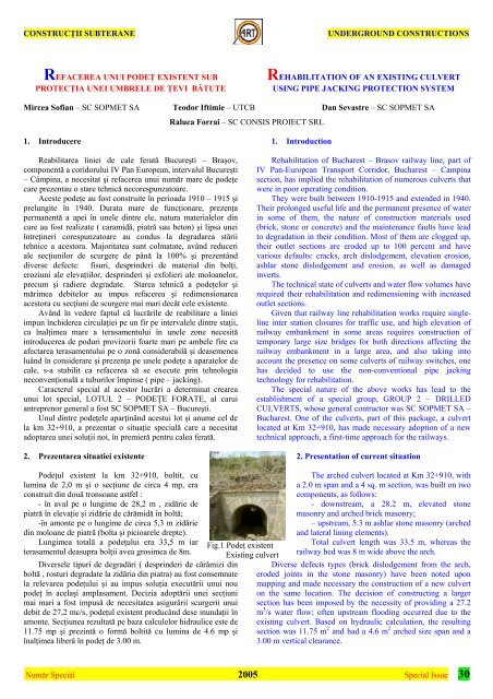
Fig.1 Podeţ existent<br />
Existing culvert<br />
Diversele tipuri de degradări ( desprinderi de cărămizi din Diverse defects types (brick dislodgement from the arch,<br />
boltă , rosturi degradate la zidăria din piatra) au fost consemnate eroded joints in the stone masonry) have been noted upon<br />
la relevarea podeţului şi au impus soluţia executării unui nou mapping and made necessary the construction of a new culvert<br />
podeţ în acelaşi amplasament. Decizia adoptării unei secţiuni on the same location. The decision of constructing a larger<br />
mai mari a fost impusă de necesitatea asigurării scurgerii unui section has been imposed by the necessity of providing a 27.2<br />
debit de 27,2 mc/s, podeţul existent producând dese inundaţii în m<br />
amonte. Secţiunea rezultată pe baza calculelor hidraulice este de<br />
11.75 mp şi prezintă o formă boltită cu lumina de 4.6 mp şi<br />
înalţimea liberă în podeţ de 3.00 m.<br />
3 /s water flow; often upstream flooding occurred due to the<br />
existing culvert. Based on hydraulic calculation, the resulting<br />
section was 11.75 m 2 and had a 4.6 m 2 arched size span and a<br />
3.00 m vertical clearance.<br />
Număr Special 2005<br />
Special Issue 30
CONSTRUCŢII <strong>SUB</strong>TERANE<br />
3. Descrierea noii soluţii<br />
Secţiunea noului podeţ are următoarea alcătuire;<br />
• umbrela de ţevi (Ø 270 mm) la extradosul noii structuri şi<br />
în contact cu terasamentul;<br />
• susţinere provizorie pe perioada execuţiei realizată din<br />
cintre metalice compuse din profile cornier şi tole metalice<br />
sudate între acestea;<br />
• hidroizolaţie intermediară din membrană bituminoasă;<br />
structura de rezistenţă cu forma boltită (Ri=2.30m) şi radier<br />
drept, realizată din beton armat cu grosimea de 55 cm;<br />
Fig. 2 Dispoziţie generală şi seţiune transversală podeţ nou<br />
Podeţul proiectat şi realizat are lungimea totală de 34,00 m<br />
şi este alcătuit din două tronsoane de capăt cu lungimea de 2,00<br />
m şi cinci tronsoane curente cu lungimea 6,00 m fiecare.<br />
Realizarea unei astfel de secţiuni cu metoda clasică ar fi<br />
necesitat poduri provizorii cu deschideri mari (21,00 m ) pe<br />
ambele fire , închideri de linii, costuri mari. Noua soluţie<br />
adoptată elimină toate aceste dezavantaje, prin utilizarea unei<br />
tehnologii specifice construcţiilor subterane, posibilă prin<br />
realizarea prealabilă a unei umbre de ţevi.<br />
Descrierea tehnologiei de execuţie<br />
Ordinea de execuţie a lucrărilor este următoarea:<br />
Etapa 1.- Realizarea bolţii din ţevi bătute orizontal<br />
• Se execută dispozitivul de batere şi se bat ţevile 7 ' - 0 – 7<br />
de o parte şi de alta a axului podeţului existent (Fig.3);<br />
• Se execută sapatura în faţa şi în spatele timpanului existent<br />
amonte;<br />
3. Description of new solution<br />
UNDERGROUND CONSTRUCTIONS<br />
The cross-section of the new culvert consists in:<br />
• pipes umbrella( Φ=270 mm) at the the back of arch of the<br />
cuvert and in contact with the railway bed<br />
• temporary support with steel framework with end plates<br />
welded in between.<br />
• waterproofing of bituminous membrane<br />
• vaulted structure (Ri=2.30m) and plane invert, made of<br />
reinforced concret 55cm thickness<br />
Figure 2. General lay-out and cross-section of the new culvert<br />
This new culvert is 34 m length and consist in: 2 end sections of<br />
2 meters length and 5 intermediary sections of 6 m length.<br />
Performance of this kind of section with the traditional methods<br />
would have supposed: temporary bridges with spans of 21<br />
meters length, , closure of railway traffic and major costs. The<br />
new adopted technology expel all the above mentioned<br />
disadvantages, by using a specific undergroun constructions<br />
solution.<br />
Technology description<br />
The execution order of the works is as follows:<br />
Stage 1. The performance of the horizontal pipes arch.<br />
• the driving device is performed and the pipes no.7-0-7’ are<br />
pushed on both sides of the existing culvert.<br />
• excavation is performed in front of and at the back of the<br />
existing upstream tympan.<br />
Număr Special 2005<br />
Special Issue 31
CONSTRUCŢII <strong>SUB</strong>TERANE<br />
Fig. 3 Diagramă batere ţevi, baterea primei ţevi şi situaţia<br />
finală<br />
Se demolează parţial timpanul pentru a putea continua baterea<br />
ţevilor 17' – 8 'si 8 – 17;<br />
• Se execută sapatura la cotele din proiect şi se toarnă betonul<br />
de egalizare 15 cm grosime , între fundaşiile podeţului<br />
existent;<br />
Etapa 2.- Execuţia radierului tronsonului de capăt ( timpan)<br />
L= 2, 00 m<br />
• Se demolează structura existenta pe 2,50 m şi se sprijină<br />
provizoriu bolta existentă în front cu cintre metalice;<br />
Fig. 4 Execuţie radier tronson de capăt<br />
• Se execută sapatura la cotele din proiect pentru execuţia<br />
radierului pe 2,00 m;<br />
• Se montează cintrul metalic aferent următorului tronson;<br />
• Se completează betonul de egalizare de 15 cm grosime;<br />
• Se armează, se cofrează şi se betonează radierul;<br />
Etapa 3 – Execuţia elevaţiei tronsonului de capat L= 2,00 m<br />
şi a primului tronson de radier al inelului 1, L = 3,00 m<br />
• Se montează armatura, se cofrează şi se betonează elevaţia<br />
tronsonului de capăt ( timpan);<br />
• Se execută hidroizolaţia la extradosul tronsonului de capat;<br />
• Se demolează structura existentă pe 3,50 m şi se sprijină<br />
provizoriu bolta în front cu cintre demontabile;<br />
• Se execută săpatura la cotele din proiect pentru realizarea<br />
radierului pe 3,00 m;<br />
• Se montează cintrele metalice pierdute la intradosul ţevilor;<br />
UNDERGROUND CONSTRUCTIONS<br />
Figure 3 Pipe jacking diagram, first pipejacking and final<br />
situation<br />
• existing tympan is partially demolished in order to continue<br />
the driving of pipes no17’-8-17<br />
• the excavation is performed based on the blueprint, a 15 cm<br />
layer of levelling concrete is poured in between the<br />
foundations of the existing culvert;<br />
Stage 2. Construction of the 2 m end section element<br />
• existing structure is demolished on a 2.50 m length and the<br />
existing arch is temporarily supported by steel frameworks<br />
Figure 4 Construction of end section invert<br />
• A 2 m-long excavation is performed based on the blueprint<br />
in order to construct the invert<br />
• steel framework is installed, to be used for next section;<br />
• the levelling concrete is completed up to a 15 cm width;<br />
• invert is reinforced, encased and concreted.<br />
Stage 3 – Construction of the end section elevation L = 2.00<br />
m and the first invert section of the ring 1 L = 3.00 m<br />
• reinforcement and encasement are performed, then the end<br />
section element elevation is concreted;<br />
• waterproofing is performed at the end section back arch;<br />
• existing structure is demolished on a 3.50 m length and the<br />
existing arch is supported by removable frame steelworks<br />
• excavation is performed based on blueprint in order to<br />
construct the invert on a 3 m length<br />
• frame steelworks are put in place at the pipes’ intrados<br />
Număr Special 2005<br />
Special Issue 32
CONSTRUCŢII <strong>SUB</strong>TERANE<br />
• Se montează tolele metalice sudate de cintre;<br />
• Se completeză betonul de egalizare de 15 cm;<br />
• Se realizează rostul total cu 2 foi de carton bitumat, între<br />
tronsonul de capat si cel curent;<br />
• Se execută hidroizolaţia şi se petrece cu cea din etapa<br />
anterioară;<br />
• Se armează, se cofrează şi se betonează radierul pe 3,00 m;<br />
Fig.5 Armare timpan şi cofraj metalic mobil pentru betonare<br />
Etapa 4 – Execuţia primului tronson de boltă L = 2,00 m şi a<br />
celui de al doilea tronson de radier cu L = 3,00 m<br />
• Se armează, se cofrează şi se betonează primul tronson de<br />
bolta de 2,00 m;<br />
• Se demolează structura existentă pe 3,5 m şi se sprijină<br />
provizoriu bolta existentă în front , cu cintre demontabile;<br />
Se execută săpatura la cotele din proiect pentru realizarea<br />
radierului L= 3,00m;<br />
Fig.6 Faze de execuţie ine1 şi imagine montare cintre.<br />
• Se montează cintrele metalice pierdute la intradosul ţevilor;<br />
• Se montează tolele metalice sudate de cintre pe tronsonul<br />
pe care s-a betonat radierul;<br />
• Se execută hidroizolaţia şi se petrece cu cea executată în<br />
etapa anterioară;<br />
• Se completează betonul de egalizare de 15 cm grosime;<br />
• Se armează, se cofrează şi se betonează radierul pe o<br />
UNDERGROUND CONSTRUCTIONS<br />
• end plates are welded in between the frame steelworks<br />
• the levelling concrete is completed up to a 15 cm width<br />
• the total joint is made using 2 asphalt board sheets, between<br />
the end section and the current section.<br />
• waterproofing is performed and meets the one performed<br />
during the previous stage.<br />
• invert section 1 of the next ring is reinforced, cased and<br />
concreted on a 3 m length.<br />
Fig.5. Reinforcement of the tympan and mobile metallic casing<br />
for concreting.<br />
Stage 4-Construction of the first arch section, L=2m, and<br />
the second invert section, L=3.00m.<br />
• reinforcement and encasement are performed, then the first<br />
arch section is concreted;<br />
• existing structure is demolished on a 3.50 m length and the<br />
existing arch is temporarily supported by removable frame<br />
steelworks.<br />
An excavation is performed based on the blueprint in order to<br />
construct the invert on a 3.0 m length<br />
Fig. 6 Stages of construction of the ring 1 and installing of<br />
frame steelworks<br />
• frame steelworks are put in place at the pipes’ intrados<br />
• metallic end plates welded on frame steelworks are<br />
installed in the section where the invert was concreted<br />
• waterproofing is performed and meets the one performed<br />
during the previous stage<br />
• the levelling concrete is completed up to a 15 cm thickness;<br />
• invert is reinforced, encased and concreted on a 3.00<br />
Număr Special 2005<br />
Special Issue 33
CONSTRUCŢII <strong>SUB</strong>TERANE<br />
lungime de 3,00 m;<br />
Etapa 5 – Execuţia celui de al doilea tronson de boltă L=<br />
2,00 m şi a primului tronson de radier L= 3,00 m pentru un<br />
inel nou<br />
• Se armează, se cofrează şi se betonează al doilea tronson de<br />
boltă de 2,00 m al primului inel;<br />
• Se demolează structura existentă pe 3,50 m şi se sprijină<br />
provizoriu bolta existenta în front, cu cintre demontabile;<br />
• Se execută sapatura la cotele din proiect pentru realizarea<br />
radierului pe o lungime de 3,0m;<br />
• Se montează cintrele metalice pierdute la extradosul ţevilor;<br />
• Se montează tolele metalice sudate de cintre pe tronsonul<br />
pe care s-a betonat radierul;<br />
• Se realizează rostul total cu 2 foi de carton bitumat între<br />
bolţari la nivelul radierului;<br />
Fig. 7 Armare şi betonare boltă.<br />
• Se execută hidroizolaţia şi se petrece cu cea executată în<br />
etapa anterioară;<br />
• Se completează betonul de egalizare de 15 cm grosime;<br />
• Se armează, se cofrează şi se betonează tronsonul 1 de<br />
radier al urmatorului inel;<br />
Etapa 6 – Execuţia ultimului tronson de bolta al inelului 1<br />
• Se armează, se cofreaza şi se betonează al treilea tronson de<br />
2,00 m, al primului inel;<br />
• Se realizează rostul total cu 2 foi de carton bitumat între<br />
inele la nivelul bolţii;<br />
Se repetă etapele 2,3,4,5 si 6, pana se finalizează podeţul<br />
Fig. 8 Imagini finale timpan aval şi amonte<br />
meters length<br />
UNDERGROUND CONSTRUCTIONS<br />
Stage 5- Construction of the second arch section, L=2m, and<br />
the first invert section, L=3.00m for a new ring.<br />
• reinforcement and encasement are performed, then the<br />
second arch section L=2.00 m of the first ring is concreted;<br />
• existing structure is demolished on a 3.50 m length and the<br />
existing arch is temporarily supported by removable frame<br />
steelworks<br />
• an excavation is performed based on the blueprint in order<br />
to construct the invert on a 3.0 m length<br />
• frame steelworks are put in place at the pipes’ intrados<br />
• metallic end plates welded on frame steelworks are<br />
installed in the section where the invert was concreted<br />
• total joint is made using 2 asphalt board sheets in between<br />
the lining segments at the invert level.<br />
Figure 7 Arch reinforcement and concreting<br />
• waterproofing is performed and meets the one performed<br />
during the previous stage<br />
• the levelling concrete is completed up to a 15 cm thickness<br />
• invert section 1 of the next ring is reinforced, cased and<br />
concreted.<br />
Stage 6 – Construction of last arch section of ring 1<br />
• reinforcement and encasement are performed, then the third<br />
arch section of 2 m length of the first ring is concreted;<br />
• total joint is made using 2 asphalt board sheets in between<br />
the rings at the arch level<br />
Stages 2, 3, 4, 5 and 6 are repeated until the culvert is completed<br />
Fig. 8 Final images end element upstream and downstream<br />
Număr Special 2005<br />
Special Issue 34
CONSTRUCŢII <strong>SUB</strong>TERANE<br />
4. Concluzii<br />
Utilizarea noii tehnologii de refacere a unui podeţ, sub un<br />
terasament înalt, prin utilizarea unei umbrele de ţevi a constituit<br />
un succes deplin atât prin calitatea noii lucrări cât şi prin<br />
avantajele incontestabile faţă de tehnologia clasică cu săpătură<br />
deschisă şi poduri provizorii.<br />
Aceste avantaje sunt:<br />
- reducerea totală a tasărilor;<br />
- eliminarea închiderilor de circulaţie şi a perturbării<br />
traficului;<br />
- scurtarea duratei de execuţie;<br />
- reducerea costului;<br />
Avantajele enumerate mai sus, nivelul calitativ al noii<br />
lucrări şi experienţa câştigată sunt argumente importante în<br />
favoarea utilizării noii tehnologii şi în alte situaţii similare.<br />
4. Conclusions<br />
UNDERGROUND CONSTRUCTIONS<br />
The use of new culvert rehabilitation technology, under a high<br />
railway bed, using pipe jacking protection system has been an<br />
outright success in terms of both quality of the new construction<br />
and certain advantages towards the classic “cut-and-cover” and<br />
temporary bridge technology.<br />
These advantages are:<br />
• eradication of sagging<br />
• fewer traffic closures and decreased perturbation of<br />
traffic<br />
• shorter construction time<br />
• reduced costs<br />
The above advantages, combined with the high quality<br />
standards of the new work as well as the expertise earned<br />
throughout the construction process are important factors that<br />
plead for the use of new technology in similar situations.<br />
Număr Special 2005<br />
Special Issue 35