REFACEREA UNUI PODEŢ EXISTE SUB PROTECŢIA UNEI ... - CFDP
REFACEREA UNUI PODEŢ EXISTE SUB PROTECŢIA UNEI ... - CFDP
REFACEREA UNUI PODEŢ EXISTE SUB PROTECŢIA UNEI ... - CFDP

You also want an ePaper? Increase the reach of your titles
YUMPU automatically turns print PDFs into web optimized ePapers that Google loves.
CONSTRUCŢII <strong>SUB</strong>TERANE<br />
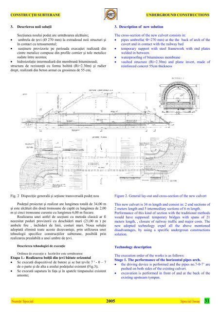
3. Descrierea noii soluţii<br />
Secţiunea noului podeţ are următoarea alcătuire;<br />
• umbrela de ţevi (Ø 270 mm) la extradosul noii structuri şi<br />
în contact cu terasamentul;<br />
• susţinere provizorie pe perioada execuţiei realizată din<br />
cintre metalice compuse din profile cornier şi tole metalice<br />
sudate între acestea;<br />
• hidroizolaţie intermediară din membrană bituminoasă;<br />
structura de rezistenţă cu forma boltită (Ri=2.30m) şi radier<br />
drept, realizată din beton armat cu grosimea de 55 cm;<br />
Fig. 2 Dispoziţie generală şi seţiune transversală podeţ nou<br />
Podeţul proiectat şi realizat are lungimea totală de 34,00 m<br />
şi este alcătuit din două tronsoane de capăt cu lungimea de 2,00<br />
m şi cinci tronsoane curente cu lungimea 6,00 m fiecare.<br />
Realizarea unei astfel de secţiuni cu metoda clasică ar fi<br />
necesitat poduri provizorii cu deschideri mari (21,00 m ) pe<br />
ambele fire , închideri de linii, costuri mari. Noua soluţie<br />
adoptată elimină toate aceste dezavantaje, prin utilizarea unei<br />
tehnologii specifice construcţiilor subterane, posibilă prin<br />
realizarea prealabilă a unei umbre de ţevi.<br />
Descrierea tehnologiei de execuţie<br />
Ordinea de execuţie a lucrărilor este următoarea:<br />
Etapa 1.- Realizarea bolţii din ţevi bătute orizontal<br />
• Se execută dispozitivul de batere şi se bat ţevile 7 ' - 0 – 7<br />
de o parte şi de alta a axului podeţului existent (Fig.3);<br />
• Se execută sapatura în faţa şi în spatele timpanului existent<br />
amonte;<br />
3. Description of new solution<br />
UNDERGROUND CONSTRUCTIONS<br />
The cross-section of the new culvert consists in:<br />
• pipes umbrella( Φ=270 mm) at the the back of arch of the<br />
cuvert and in contact with the railway bed<br />
• temporary support with steel framework with end plates<br />
welded in between.<br />
• waterproofing of bituminous membrane<br />
• vaulted structure (Ri=2.30m) and plane invert, made of<br />
reinforced concret 55cm thickness<br />
Figure 2. General lay-out and cross-section of the new culvert<br />
This new culvert is 34 m length and consist in: 2 end sections of<br />
2 meters length and 5 intermediary sections of 6 m length.<br />
Performance of this kind of section with the traditional methods<br />
would have supposed: temporary bridges with spans of 21<br />
meters length, , closure of railway traffic and major costs. The<br />
new adopted technology expel all the above mentioned<br />
disadvantages, by using a specific undergroun constructions<br />
solution.<br />
Technology description<br />
The execution order of the works is as follows:<br />
Stage 1. The performance of the horizontal pipes arch.<br />
• the driving device is performed and the pipes no.7-0-7’ are<br />
pushed on both sides of the existing culvert.<br />
• excavation is performed in front of and at the back of the<br />
existing upstream tympan.<br />
Număr Special 2005<br />
Special Issue 31