Apollo 204 Review Board Appendix C Section 2 - NASA's History ...
Apollo 204 Review Board Appendix C Section 2 - NASA's History ...
Apollo 204 Review Board Appendix C Section 2 - NASA's History ...

Create successful ePaper yourself
Turn your PDF publications into a flip-book with our unique Google optimized e-Paper software.
SMa:\-03-SC01Z<br />
APOLLO OPERATIONS HANDBOOK<br />
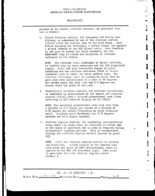
purpose of the manual attitude controls "md pertinent data<br />
are as follo_.;s:<br />
i° Direct rotation control, for emergency and backup con-<br />
ditions, is commanded by use of the rotation control<br />
(stick) about the desired axes to its hard stops. Just<br />
before engaging the hardstops, a s_itch closes and applies<br />
a direct command to the RCS direct coils. Rate feedback<br />
is not used to cancel the stick movement, but the<br />
BMAG-AGCU loop is closed and maintains an attitude<br />
reference to its limits.<br />
NOTE The attitude rate,_commanded by direct rotation,<br />
is limited only by human endurance and the RCS propellant<br />
supply. Start and stop transients depend on pilot<br />
technique and the attitude reference (FDAI or visual<br />
!andmark) used to close +he outer control loop. The<br />
inertial references start to accumulate error (due to<br />
gyro slue rate limitations) at a rate of 20 degrees<br />
per second about the roll _xis and 5.0 degrees per<br />
second about the pitch or yaw axis.<br />
. Proportional rotation control_ for attitude corrections,<br />
is commanded by displacement of the manual S/C rotation<br />
control (stick) into a desired proportional rate (_hen<br />
referring to S/C attitude display on the FDAI).<br />
NOTE The resulting proportional rate will vary from<br />
a minimum of 0.2 degree per second to a maximum of<br />
0.65 degree per second (depending on stick dis_ldce-<br />
ment). Attitude error deadbands are ±4.2 degrees<br />
maximum _nd ±0.2 decree _inimum.<br />
Attitude impulse control, for co.._manding low-rotational<br />
rates about all three axes, is available in either G&N<br />
or SCS modes of operation and is used as required during<br />
navigational sighting periods. This is accomplished<br />
through the attitude impulse control located on panel<br />
!05.<br />
NOTE After the _ttitude impulse control is enabled<br />
an_ disp!uced, u s_itch closure in the control unit<br />
vlill cause one pulse of 18±4 _illiseconds, which is<br />
_pplied to the RCS jet selection logic. (One pulse<br />
is generated for e_ch uttitude impulse switch<br />
closure.)<br />
Basic Date 1_2 i;o'.- i766<br />
RC,C .2_', gF2 THRUST!I. _] EAT,.\<br />
Revision D_tte Page _6<br />
]<br />
I<br />
I<br />
I<br />
I<br />
I<br />
I<br />
I<br />
I<br />
I<br />
l<br />
[