Apollo 204 Review Board Appendix C Section 2 - NASA's History ...
Apollo 204 Review Board Appendix C Section 2 - NASA's History ...
Apollo 204 Review Board Appendix C Section 2 - NASA's History ...

You also want an ePaper? Increase the reach of your titles
YUMPU automatically turns print PDFs into web optimized ePapers that Google loves.
I<br />
I<br />
I<br />
I<br />
I<br />
I<br />
I<br />
I<br />
I<br />
I<br />
I<br />
I<br />
I<br />
I<br />
]<br />
4.1<br />
System<br />
SPS<br />
(_C-20)<br />
(fig-<br />
ure h-l)<br />
Basic Date<br />
INTRODUCTION..<br />
SMZA-03-SC012<br />
APOLLO OPERATIONS HANDBOOK<br />
PERFORMANCE<br />
SECTION 4<br />
PERFORMANCE<br />
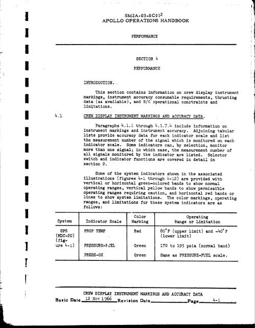
This section contains information on crew display instrument<br />
markings, instrument accuracy consumable requirements, thrusting<br />
data (as available), and S/C operational constraints and<br />
limitations.<br />
CREW DISPLAY INSTRUMENT MARKINGS AND ACCURACY DATA.<br />
Paragraphs 4.1.1 through 4.1.7.4 include information on<br />
instrument markings and instrument accuracy. Adjoining tabular<br />
lists provide accuracy data for each indicator scale and list<br />
the measurement number of the signal which is monitored on each<br />
indicator scale. Some indicators can, by selection, monitor<br />
more than one signal; in which case, the measurement number of<br />
all signals monitored by the indicator are listed. Selector<br />
switch and indicator functions are covered in detail in<br />
section 2.<br />
Some of the system indicators shown in the associated<br />
illustrations (figures 4-1 through _-12) are _rovided with<br />
vertical or horizontal green-coloredbands to show normal<br />
operating ranges, vertical yellow bands to show permissible<br />
operating ranges requiring caution, and horizontal red bands or<br />
lines to show system limitations. The color markings, operating<br />
ranges, and limitations for these system indicators are as<br />
follows:<br />
Indicator Scale<br />
PROP T_hP<br />
PRESSURE-_ JEL<br />
PRESS-OX<br />
,r •<br />
Color<br />
Marking<br />
Red<br />
Green<br />
Green<br />
Operating<br />
Range or Limitation<br />
80°F (upper limit) and -hO°F<br />
(lower limit)<br />
170 to 195 psia (normal band)<br />
Same as PRESSURE-FUEL scale.<br />
CREW DISFLAY INSTRUMENT MARKINGS AND ACCURACY DATA<br />
12 Nov 1966 Revision Date Page .... 4-i _ .<br />
[
System Indicator Scale<br />
PRESSURE-ENG<br />
INLET-FUEL<br />
PRESSURE-ENG<br />
INLET-OX<br />
• SPS L/V AOA/SPS Pc<br />
(MDC-3) indicator<br />
(figure._-il)<br />
EPS TANK PRESSURE-<br />
(MDC-13) H2_ 1<br />
(figure<br />
_-3) TANK PRESSURE-<br />
H2-2<br />
TANK PRESSURE-<br />
02-1<br />
TANK PRESSURE-<br />
02-2<br />
(MDC-18) FUEL CELL-FLOW-<br />
(fig- H2<br />
ure 4-5)<br />
FUEL CELL-FLOW-<br />
O 2<br />
FUEL CELL-MODULE<br />
TEMP-SKIN<br />
FUEL CELL-MODULE<br />
TEMP-COND EXH<br />
ECS PRESS .GLY DISCH<br />
( oc-13)<br />
(fig- TEMP-SUIT<br />
ure !_-))<br />
PRESS-SUIT<br />
SM2A-03-SC012<br />
APOLLO OPERATIONS HANDBOOK<br />
PERFORMANCE<br />
Color<br />
Marking<br />
Green<br />
Green<br />
Green<br />
Green<br />
Green<br />
Green<br />
Green<br />
Green<br />
Green<br />
Green<br />
Green<br />
Green<br />
Red<br />
Operating<br />
Range or Limitation<br />
STATIC 170 to 195 psia (normal<br />
band)<br />
FIRE 135 to 165 psia (normal<br />
band)<br />
Same as PRESSURE-ENG INLET-<br />
FUEL scale.<br />
SPS FIRE 65 to 125% (normal<br />
band)<br />
230 to 265 psia (normal band)<br />
Same as TANK PRESSURE_H2_ I<br />
scale.<br />
865 to 935 psia (normal band)<br />
Same as TANK PRESSURE_02.1 scale<br />
0.03 to 0.15 ib/hr (nOrmal band)<br />
0.25 to 1.20 ib/hr (normal band)<br />
385" to 495°F (normal band)<br />
157.5 ° to 172.5"F (normal band)<br />
35 to 55 psia (normal band)<br />
45 ° to 65@F (normal band)<br />
3.h psia (lOw limit line)<br />
CREW DISPLAY INSTRUMENT MARKINGS AND ACCURACY DATA<br />
Basic Date,,__[_ _Jov 1966 . Revision Date _Page
I<br />
I<br />
I<br />
I<br />
I<br />
I<br />
i<br />
I<br />
i<br />
I<br />
I<br />
I<br />
I<br />
]<br />
]<br />
I<br />
!<br />
System<br />
PGA<br />
(figire<br />
4-9 )<br />
4.1.1<br />
PROP TEMP.<br />
SM2A-03-SC0ZZ<br />
APOLLO OPERATIONS HANDBOOK<br />
Indicator Scale<br />
PRESS-CABIN<br />
PART PRESS-CO 2<br />
PGA pressure<br />
indicator<br />
PERFORMANCE<br />
Color<br />
Marking<br />
Red<br />
Red<br />
Yellow ......<br />
Red<br />
Green<br />
SERVICE PROPULSION SYSTEM INDICATORS.<br />
i<br />
Operating<br />
Range or Limitation<br />
h.7 psia (low limit llne)<br />
15 mm Hg (high limit line)<br />
7.6 to 15 mm Hg (caution band)<br />
2.0 to 3.5 psia (emergency band)<br />
3.5 to I0 psia (normal band)<br />
Instrument markings for the SPS indicators (MDC-20) are<br />
shown in figure 4-i. The indicators present a visual display of<br />
SPS temperatures and pressures. Visual displays of SPS fuel and<br />
oxidizer remaining aboard the S/C are shown in the adjacent<br />
OXID-FUEL QUANTITY display windows (as selected by the SPS<br />
quantity SENSOR switch). (Refer to section 3.)<br />
I PRESSURE ,r I<br />
ENG INLET<br />
He<br />
PRESS EUEL OX FUEL OX •<br />
N2<br />
L.. TK PRESS.-]<br />
NOTE: Red lines on the propellant tempQmture<br />
t_[e show upper limit of<br />
80eF ond lower limit of "40OF.<br />
Vertical green _lOt bends I/_)W<br />
nQrmol opemtlng ranges for fuel<br />
and oxld;zer pretture (170 to 195<br />
ptIo) and engine inlet prcmur_<br />
for STATIC (170 to 195 role)end<br />
FiRE (135 to 165 pt;@).<br />
ii<br />
SM-2A-_m<br />
Figure _. t. Service Propulsion System Indicators<br />
..... i I ..... 7r[ " -- -f" i[-till-- II<br />
CREW DISPLAY INSTRUMENT MARKINGS AND ACCURACY DATA<br />
Basic Date--_-2-N°v L_66 Revision Date ...... Pose _. h-3 .....
SM2A-03-SC012<br />
APOLLO OPERATIONS HANDBOOK<br />
PERFORMANCE<br />
1<br />
The accuracy for each indicator scale and the measurement _,<br />
number of the associated signal is as follows:<br />
Indicator Scale Measurement Numbe._" Indicator Accuracy lW<br />
' PROP TEMP SP 0002 T +-5@F at 75"F I<br />
-+I0@F at 0 ° and 150"F I<br />
He PRESS SP 0001 P<br />
+<br />
_I00 psia at<br />
" @<br />
75 F<br />
+150 psia at 0" and 150 °F<br />
, %% @ •<br />
Tk PRESS-N o SP 0600 P (Primary) _i00 psia at 75 F<br />
i - SP 0601 P (Secondary) +-150 psia at 0 ° and 150°F<br />
| PRESSURE-FUEL SP 0006 P +5 psia at 75"F<br />
+-I0 psia at O" and 150@F<br />
PRESSURE-0X<br />
PRESSURE-ENG<br />
INLET-FUEL<br />
PRESSURE-ENG<br />
INLET-OX<br />
sP 0003 P<br />
SP 0010 P<br />
sP 0009 P<br />
REACTION CONTROL SYST_4 INDICATORS.<br />
+-5 psia at 75"F<br />
-+i0 psia at 0 ° and 1506F<br />
-+5 psia at 75°F<br />
+-I0 psia at 0 ° and 150°F<br />
+-5 psia at 75°F<br />
+-I0 psia at 0 ° and 150"F<br />
Instrument markings for the S/M and C/M RCS indicators<br />
(MDC-12) are shown in figure 4-2. The indicators present a<br />
visual display of system temperatures and pressures. Visual<br />
displays of S/M BCS fuel and oxidizer remaining are shown on the<br />
adjacent PROPELLANT QUANTXTY_indicator.(as selected by the RCS<br />
INDICATORS switch). (Refer to section 3.)<br />
The accuracy for each indicator scale and the measurement<br />
number of the associated signal, is as follows:<br />
Indicator Scale Measurement Number indicator Accuracy<br />
S/M RCS-TSMP PKG SR 5065 T (Quad A)<br />
SR 5066 T (Quad B)<br />
SR 5067 T (Quad C)<br />
SR 5068 T (Quad D)<br />
+-5"F at 75"F<br />
±IO'F at O" and 150"F<br />
CREw DISPLAY IfISTRU_NT M._/_KINGS A_ ACCURACY DATA<br />
BaSic Date L_ N_!:._LQ6:5 .... R_,vi.ion Date ....... Page ..... _'_ ....<br />
I<br />
O_<br />
l<br />
|<br />
I<br />
I<br />
!<br />
I<br />
I<br />
!<br />
i<br />
I<br />
i<br />
!<br />
I
f<br />
I<br />
i<br />
i<br />
i<br />
!<br />
I<br />
!<br />
I<br />
i<br />
i<br />
!<br />
I<br />
I<br />
I<br />
l<br />
T<br />
Indicator Scale<br />
S/M RCA-PRESS-H e<br />
S/M RCS-PRESS-MANF<br />
S/M RCS-TEMP He<br />
C/M RCS-H e TEMP<br />
C/M RCS-PRESS-H e<br />
C/M RCS-PRESS-F<br />
C/M RCS-PRESS-OX<br />
SM2A-03-SC012<br />
APOLLO OPERATIONS HANDBOOK<br />
PEBFORMANCE<br />
Measurement Number<br />
SR 5001 P (Quad A)<br />
SR 5002 P (Quad B)<br />
SR 5O03 P (Quaa C)<br />
SR 500h P (Quaa D)<br />
SR 5729 P (Quad A)<br />
SR 5776 P (Quad B)<br />
SR 5817 P (Quad C)<br />
SR 5830. P (Quad D)<br />
SR 5013 T (QuadA)<br />
SR 5014 T (Quad B)<br />
SR 5015 T (Quad C)<br />
ST 5016 T (Quad D)<br />
CR 0003 T (System A)<br />
CR 0004 T (System B)<br />
CR 0001 P (System A)<br />
CR 0002 P (System B)<br />
CR 0005 P (System A)<br />
CR 0006 P (System B)<br />
CR 0011 P (System A)<br />
CR 0012 P (System B)<br />
ELECTRICAL POWER SYSTEM iNDICATORS.<br />
Indicator Accuracy<br />
±i00 psia at 75"F<br />
±150 psia at 0 ° and 150'F<br />
At 75'F, ±5 psia from 140<br />
to 340 psia and ±I0 psia<br />
over balance of scale. At 0"<br />
and 150°F, ±I0 psia from 145<br />
to 340 psia and ±15 psia over<br />
balance of scale.<br />
Same as S/M RCS-PRESS-<br />
MANF indicator<br />
±5°F at 75°F<br />
±I0°F at 0° and 150°F<br />
±i00 psia at 75"F<br />
±150 psia at 0° and 150'F<br />
Same as S/M RCS-PRESS-<br />
MANF indicator.<br />
Same as S/M RCS-PRESS-<br />
MANF indicator.<br />
EPS (Cryogenic Storage) Tank Pressure Indicators.<br />
Instrument markings for the EPS (cryogenic storage) tank<br />
pressure indicators (MDC-13) are shown in figure 4-3. The<br />
accuracy for each indicator scale and the measurement number of<br />
the associated signal is as follows:<br />
NOTE TANK PRESSURE-02-1 scale is used to display<br />
cryogenic storage tank i pressure or ECS surge tank<br />
pressure as selected by 02 PRESS IND toggle switch<br />
located immediately below the display.<br />
..... [ " F<br />
CREW DISPLAY INSTRUMENT MARKINGS AND ACCURACY.DATA<br />
Basic Date .]_Nc_'.-l._5--Revision Date ...... Pase .......4-_ ......
Figure 4-2.<br />
SM2A-03-SC01 2<br />
APOLLO OPERATIONS HANDBOOK<br />
PERFORMANCE<br />
I S/M RCS<br />
TEMP , PRESS I TEMP<br />
PKG He MANF He<br />
He He F OX<br />
I"EMP I PRESS- , i<br />
I C/M RCS •<br />
S/M and C/M Reaction Control System Indicators<br />
SM-2A-688C<br />
Indicator Scale Measurement Number Indicator Accuracy<br />
TANK PRESSD-RE-H2-1 SF 0039 P<br />
TANK PRESSLrRE-H2-1 SF OO4O P<br />
TANK PRESSURE-02-1 SF 0037 P (Storage tank)<br />
CF 0006 P (Surge tank)<br />
TANK PRESSURE-02-2 SF 0038 P<br />
±5 psia at 75°F<br />
±lO psia at 0 ° and 150°F<br />
Same as TANK PRESSURE-<br />
H2-1 indicator.<br />
At 750F, ±5 psia at 850 to<br />
950 psia and z3% of remain-<br />
ing scale.<br />
At 0 ° and 150°F, ±I0 psia at<br />
850 tq 950 psia and 4% of<br />
remaining scale.<br />
Same as TANK PRESStrRE-<br />
02-2 indicator.<br />
CREW DIsP-I.AY INSTR_4ENT MABKINGS AND ACCURACY DATA<br />
_3 :L:v L>66.. Revision Date - Page<br />
|<br />
Ill<br />
--qF<br />
I<br />
|_<br />
I<br />
I .i<br />
1<br />
1<br />
1<br />
1<br />
I<br />
i<br />
I<br />
I<br />
1
- |<br />
i '<br />
i ' I<br />
I<br />
I<br />
I<br />
I<br />
I<br />
I<br />
I<br />
I<br />
I<br />
I<br />
I<br />
1-<br />
H2<br />
SMZA- 03-SC012<br />
APOLLO OPERATIONS HANDBOOK<br />
, TANK PRESSURE<br />
2 1<br />
02 2<br />
PERFOPMANCE<br />
I<br />
NOTE: Vertical green color bandson the indicators ,<br />
show normaloperating ranges for hydrogen -tank<br />
pr_ures (230 to 265 psla)and oxygen<br />
tank pressures(865 to 935 psla).<br />
SM-2A-690D<br />
Figure 4-3. EPS (Cryogenic Storage) T_nk Pressure Indicators<br />
4.1.3.2 EPS (Cryodenic Storase) Tank Quantity Indi_ators_<br />
IndicatorScale<br />
TANK QUANTITY-H2-1<br />
TANK QUANTITY-H2-2<br />
TA_ QUANTITY-02-1<br />
TANK QUANTITY-02-2<br />
Instrument markings for the EPS (cryogenic storage_ tank<br />
quantity indicator (MDC-13) are shown in figure 4-4. The<br />
accuracy for each indicator scale and the measurementnumber of<br />
the associated signal is as follows:<br />
Measurement Number<br />
SF 0030 Q<br />
SF 0031 Q<br />
SF 0032 Q<br />
SF 0033 Q<br />
Indicator Accuracy<br />
±5.0 ib at 75°F<br />
±i0.0 Ib at 0" and 150°F<br />
Same as TANK QUANTITY-<br />
02-1 indicator.
SMZA-03-SC01 Z<br />
APOLLO OPERATIONS HANDBOOK<br />
I<br />
PERFORMANCE<br />
, ,TANK QUANTITY<br />
1 H2 2 I<br />
02 2<br />
Figure 4-4. EPS (Cryogenic Storage) Tank Quantity Indicators<br />
Indicator Scale<br />
FUEL CELL-FLOW-H 2<br />
FUEL CELL-FLOW-O 2<br />
FUEL CELL-MODULE<br />
TEMP-SKIN<br />
FUEL CELL-MODULE<br />
T_P-CONI _ EXH<br />
Basic Date<br />
EPS Fuel Cell Power Plant Indicators.<br />
Instrument markings for the EPS fuel cell power plant<br />
%<br />
SM-2.A-691B<br />
indicators (MDC-18) are shown in figure 4-5. The accuracy for<br />
each indicator scale and the measurement number of the<br />
associated signal is as follows:<br />
Measurement Number Indicator Accuracy<br />
sc 2139 R (F/C i)<br />
SC 21ho R (F/C 2)<br />
SC 21hl R (F/C B)<br />
SC 2141 R (F/C l)<br />
SC 2143 R (F/C 2)<br />
SC 2144 R (F/C 3)<br />
SC 2084 T (F/C I)<br />
sc 2o85 T (F/C 2)<br />
SC 2086 T (F/C 3)<br />
SC 2081 T (F/C I)<br />
SC 2082 T (F/C 2)<br />
sc 2083 T (F/C B)<br />
±0.005 ib/hr at 75"F<br />
+-0.0075 ib/hr at 0 ° and<br />
150" F<br />
+-0.05 hr/hr at 75@F,<br />
and at 0 ° and 150°F<br />
At 75"F, ±7'F for bOO ° to<br />
550" scale and 3% of remain-<br />
ing scale. At 0 @ and 150"F,<br />
+-i_ F for 400 @ to 500" scale<br />
and 3% of remaining scale.<br />
+-3°at 75°F<br />
+-5"F at 0" and 150°F<br />
CREW DISPLA_ INSTRUMENT MARKINGS AND ACCURACY DATA<br />
i$ Nov L%6 ._Revision Daze , . Page ....<br />
4-8<br />
Qb<br />
I<br />
I<br />
I<br />
I<br />
I<br />
i<br />
i.<br />
I<br />
q<br />
I<br />
I<br />
i<br />
I<br />
1<br />
l<br />
T<br />
-,_lP
l<br />
I<br />
I<br />
I<br />
i<br />
I<br />
I<br />
I<br />
I<br />
I<br />
I<br />
I<br />
I<br />
I<br />
I<br />
l<br />
I<br />
H2<br />
4.1.3.4<br />
SM ZA- 03 -SCO 1 Z<br />
APOLLO OPERATIONS, HANDBOOK<br />
PEREO_CE<br />
-- FUEL CELL----"<br />
FLOW MODULE TEMP<br />
0 2 SKIN COND EXH<br />
Indicator Scale<br />
DC VOLTS<br />
DC AMPS<br />
Figure 4-5. EPS Fuel Cell Indicators<br />
EPS Volts, Amperes, and Frequency Meters.<br />
NOTE: Vertical green color' bonds on the lndlcotom<br />
show normol opemtt_ mnl_ for h_clrollen<br />
flow (0.03 to 0.15 Ib/l_r), c_ygen flow<br />
(0.25 to 1.25 Ib/hr), moduleddn temperoturn<br />
(385e to 495"F), and the condenserexhoust<br />
temperature(157.P to 172.5eF).<br />
Instrument markings for the EPS-volts, amperes, and<br />
SM-2A-692D<br />
frequency meters (MDC-18) are shown in figure _-o. The accuracy<br />
for each indicator scale and the measurement n_mber of the<br />
associated signal is as follows: . ,.<br />
Ii i<br />
Measurement Number<br />
CC 0206 V (Main Bus A)<br />
CC 0207 V (Main Bus B)<br />
CC 0210 V (Lat Bus A)<br />
CC 0211 V (Bat Bus B)<br />
CC 0212 V (Post Ldg Bat)<br />
CC 021h V (Bat Charger Output)<br />
CC 0227 V (Pyro Bat A).<br />
CC 0228 V (Pyro Bat B)<br />
CC 0222 C (Bat Bus A)<br />
CC 0223 C (Bat Bus B)<br />
CC 022h+C(Post Ldg Bat)<br />
SC 2113 C (F/C 1 Output)<br />
SC 211h C (F/C 2 Output)<br />
sc 2115 c (F/C 3 Output)<br />
f<br />
_ . |<br />
Indicator Accuracy<br />
At ?5+F, ±0.25 volts for 25<br />
to 37 volts scale and ±I.0<br />
volt for balance of scale.<br />
At 0 ° and 150"F, Z0.5 volts<br />
for 25 to 37 volts scale and<br />
zl.0 volt for balance of<br />
scale.<br />
Zl.0% of full scale at _5°F<br />
±2.0% of full scale at 00 to<br />
150"F<br />
CREW DISPLAY INSTRUMENT MARKINGS AND ACCUKACY DATA<br />
Basic Date ].2 Nov 1966 . Revision Date<br />
_pa8 e _'9 ......
Indicator Scale<br />
Figure 4-6.<br />
CHGR (Inner SCale)<br />
AC VOLTS<br />
FREQ CPS<br />
Basic Date<br />
SM2A-03-SC01Z<br />
APOLLO OPERATIONS HANDBOOK<br />
PERFORMANCE<br />
EPS Volts, Amperes, and Frequency Meters<br />
Measurement Number<br />
CC 0215 C (Bat Charger Output)<br />
CC 0200 V (Bus 1 _A)<br />
CC 0201 V (Bus Z CB)<br />
CC 0202 V (Bus 1 _C)<br />
CC 0203 V (Bus 2 CA)<br />
cc 020_ v (Bus 2 _B).<br />
cc o205 v (Bus 2 ¢C)<br />
CC 0213 F (Bus 1 _A)<br />
cc 0181 F (Bus 1 _B)<br />
CC 0182 F (Bus i ¢C)<br />
CC 0217 F (Bus 2 _A)<br />
CC 0183 F (Bus 2 _B)<br />
cc Ol8_ F (_,_ 2 ¢c)<br />
CREW DISPLAY INSTRUMENT MARKINGS AND ACCURACY DAT_.<br />
.L2 N,Dv £_66 Revision Date Page<br />
SM-ZA -694C<br />
Indicator Accuracy<br />
Same as DC AMPS scale<br />
Between 0 ° and 150°F,<br />
±i.0 volt for the 105<br />
and 125 volts scale<br />
and ±2.0 volts for<br />
balance of scale. At<br />
0 ° and 150°F, z2.0<br />
volts for the 105 and<br />
125 volts scale.<br />
From 50 ° to Ii0°F, ±i<br />
cycle at h00 cycles.<br />
From O' to 150°F, ±2<br />
cycles at hO0 cycles<br />
and ±2.5 cycles for<br />
balance of Scale.<br />
4- LO i<br />
i;<br />
q_<br />
l<br />
1<br />
I<br />
I<br />
1<br />
1<br />
]<br />
]<br />
!<br />
1<br />
I<br />
1<br />
I<br />
l<br />
",7
I<br />
I<br />
I<br />
I<br />
I<br />
I<br />
I<br />
I<br />
I<br />
I<br />
I<br />
I<br />
I<br />
I<br />
]<br />
7<br />
r<br />
SMZA- 03-SC012<br />
APOLLO OPERATIONS HANDBOOK<br />
PERFORMANCE<br />
4.1.4 ENVIRONMENTAL CONTROL SYSTEM INDICATORS.<br />
4.1.4.1 ECS Pressure and Slow-Rate Indicators.<br />
Indicator Scale<br />
GLY EVAP STEAM<br />
PRESS<br />
PRESS GLY DISCH<br />
FLOW 02<br />
_P SUIT COMPR<br />
4.1.4.2<br />
Indicator Scale<br />
GLY ACCUM-<br />
QUANTITY<br />
WATER QUANTITY<br />
ECS RAD-OUTLET<br />
TEMP<br />
GLY EVAP-OUTLET<br />
TEMP<br />
ECS RAD OUT TEMP-I<br />
ECS RAD OUT TEMP-2<br />
Instrument markings for the ECS pressure and rate-of-flow<br />
indicator (MDC-I3) are shown in figure 4-7. The accuracy for<br />
each indicator scale and the measurement number of the<br />
associated signal is as follows<br />
Measurement Nt_mber Indicator Accuracy<br />
CF O03h P z5% of full scale between 0 °<br />
and 150°F<br />
CF 0016 P Same as above.<br />
CF 0035 R Same as above.<br />
CF 0115 P Same as above.<br />
L<br />
ECS Quantity and Outlet Temperature indicators.<br />
Instrument markings for the ECS quantity and outlet<br />
temperature indicators (MDC 13 and 14) are shown in figure 4-8.<br />
The accuracy for each indicator scale and the measurement<br />
number of the associated signal is as follows:<br />
Measurement Number Indicator Accuracy<br />
CF 0019 Q<br />
CF 0010 Q (Potable Water)<br />
CF 0009 Q (Waste Water)<br />
CF 0020 T<br />
CF 0018 T<br />
SF 0671 T<br />
SF 0672 T<br />
+-5% full-scale 0" to 150@F<br />
Same as above.<br />
I 1111 I ..... • " i<br />
Same as above.<br />
Same as above.<br />
Same as above.<br />
Same as above.<br />
CREW DISPLAY INSTRUMENT MARKINGS AND ACCUIqACY DATA<br />
Basic Date _2 Nov ,t966_k_aevision Date , ..-- - ,Page 4-LI
OLY EVAP<br />
STEAM PRESS<br />
GLY ACCUM<br />
BasLc 'Date<br />
PRESS<br />
GLY DISCH<br />
SMZA-03-SC012<br />
APOLLO OPERATIONS HANDBOOK<br />
Figure 4-7.<br />
WATER<br />
PERFORMANCE<br />
FLOW A P I<br />
0 2 SUIT COMPR<br />
ECS Pressure and Flow Indicators<br />
NOT_: The green color b_nd on the glycol<br />
di$¢hQrge scale indlcQtes a normal<br />
Figure 4-8. ECS Quantity and Outlet Temperature Indicators<br />
m k - • i i<br />
CREW DISPLAY INSTRUMENT MARKINGS AND ACCUKACY DATA<br />
L2 Nov ];,966 Rev_sLon Date Page<br />
opermting range of 35 to 55 psia. i<br />
SM-2A-695E 1<br />
SM- 2.A- 696C<br />
4- L2<br />
i<br />
_.'II_<br />
!<br />
!<br />
]<br />
I<br />
I<br />
I<br />
I
I SMZA-03-SC012<br />
APOLLO OPERATIONS HANDBOOK<br />
I<br />
I<br />
I<br />
I<br />
I<br />
I<br />
I<br />
I<br />
I<br />
I<br />
I<br />
I<br />
i+<br />
]+<br />
T-<br />
I<br />
+<br />
4.1.4.3<br />
Indicator Scale<br />
TEMP-SUIT<br />
TEMP-CABIN<br />
PRESS-SUIT<br />
PRESS-CABIN<br />
PART PRESS-C02<br />
PGA Pressure Indicatc;r<br />
4.L.5<br />
PERFORMANCE<br />
ECS Suit and Cabin Temperature/Pressure Indicators.<br />
Instrument markings for the ECS suit and cabin temperature/<br />
_ressure indicators are shown in figure 4-9. The accuracy for<br />
each indicator scale and the measurement number of the<br />
associated signal is as follows:<br />
Measurement Number Indicator Accuracy<br />
CF 0008 T ±2.5@F overall at 0 @ to<br />
15o°F,<br />
CF 0002 T<br />
CF 0012 P<br />
CF 0001 P<br />
CF 0005 P<br />
TELECOMMUNICATION SYSTEM METERS.<br />
Same as above.<br />
At 75°F, ±0.25 psia between<br />
0 and 6 psia end ±B% for<br />
remainder of scale. At 0 °<br />
and 150°F, ±0.375 psia<br />
between 0 and 6 psia, and<br />
a4% for remainder of scale.<br />
Same as PRESS-SUIT scale.<br />
At 75°F, ±0.5 mmbetween 0<br />
and 15 mm Hg, and ±I.0 m,.m<br />
for remainder Of scale. At<br />
0° and 150°F, ±I.0 mm<br />
between 0. and 15 mm Hg,<br />
and 1.5 mr, for remainder<br />
of scale.<br />
_one z2 psia overall at normal<br />
temperature range.<br />
Instrument markings for the telecommunication system<br />
meters are shown in figure 4-iO.<br />
4.1.5.1 Auxiliary DC VOLTS Meter.<br />
The auxiliary DC VOLTS meter, located on RHFEB-200<br />
(figure 4-10), is used to monitor selected measurements for<br />
which there is either no other crew display or the crew display<br />
is an event indicator c_pable of displaying only in-tolerance<br />
and out-of-tolerance conditions. The voltmeter is used in con-<br />
Junction with the adjacent _JNCTI0_ SELECT and TEST SELECT<br />
. -+<br />
. -+<br />
CREW DISPLAY INSTRUMENT MARKINGS AND ACCURACY DATA<br />
Basic Date 12, Noy 1966 _Revision Date _.Page_ 4-i_ .......
SUIT<br />
PGA PRESSURE<br />
INDICATOR<br />
(LEFT FOREARM)<br />
5M2A-03-SC01 2<br />
APOLLO OPERATIONS HANDBOOK<br />
PERFORMANCE<br />
TEMP I [_ PREss-------]<br />
CABIN SUIT CABIN PARTPRESS<br />
CO2<br />
NOTES:. I A vertical green color bond shows the normal operating<br />
range for the suit temperature (45 ° to 65°F). Red<br />
horizontal i;nes show limits for suit pressure (3.4 ps;o),<br />
cabin pressure (4.7 ps;o), and CO2 pressure (|5 mm Hg).<br />
A vertical yellow color Ixmd shows the caution range<br />
for CO 2 pressure(7.6 to 15 mm Hg).<br />
2..The PGA pressure indicator presents an operating rOfige<br />
frcxn 2 to 10 psio and a green and red color b_nd. The<br />
green I:_nd (3.5 to 10 psio) shows normal pressure<br />
requlreddurln 9 space flight. The redb_nd(3.Sto 2pslo)<br />
shows the emergency limitations for crave safety. During<br />
ground operations, the indicator needle will be.pegged<br />
beyond 10 psio because of atmospheric pressure.<br />
Figure ..-;. ECS Suit. and. Cabin Temperature/Pressure Indicators<br />
S-BAND ANT<br />
Auxiliary DC VOI T_ Me , S-BAND ANT Meter<br />
i<br />
77Y',: "T:'FLA',"<br />
SM- 2A - 697C<br />
SM-2A-693C<br />
_T<br />
le<br />
]<br />
]<br />
1<br />
I<br />
i! t<br />
I<br />
J<br />
1<br />
I<br />
I<br />
I<br />
I<br />
I<br />
I<br />
]<br />
-p
i<br />
i<br />
i<br />
I<br />
I<br />
i<br />
I<br />
I<br />
I<br />
I<br />
I<br />
i<br />
I<br />
I<br />
I<br />
,<br />
4.1.5.2<br />
' 16<br />
4..o.L<br />
SMZA-03-SC01 2<br />
APOLLO OPERATIONS HANDBOOK<br />
PERFOP$_ANCE<br />
switches to monitor 13 EPS, 6 RCS, 4 G&N and 1 ECS analog<br />
measurements. Refer to Controls and Displays (section 3) for<br />
information on which measurements are selected for monitoring by<br />
the auxiliary DC VOLTS meter.<br />
The voltmeter provides a reading between 0 and 5 volts of<br />
the selected measurement. By use of a voltmeter conversion chart<br />
an interpolation of the value for the selected measurement can be<br />
made. (Refer to section D.)<br />
NOTE The accuracy of the auxiliary DC VOLTS meter<br />
(.for the full scale) is zl percent at 75°F.and ±2 percent<br />
at 0 ° and 150°F.<br />
S-Band ANT Meter.<br />
The S-Band ANT meter, on NDC-19 (figure 4-i0), utilizes the<br />
automatic gain control (AGC) signal in the S-Band receiver to<br />
display, in a clockwise direction, the relative magnitude of<br />
signals received by the unified S-band equipment (USBE). The<br />
meter is used in determining the correct S-band antenna and S/C<br />
attitude for optimum S-band performance.<br />
NOTE The accuracy of the S-BAND ANT meter (for the full<br />
scale) is z5 percent at temperatur@s between OOand 150°F.<br />
SEQUENTIAL SYSTY_JS INDICATORS.<br />
Instrument markings for the sequential systems indicators<br />
are sho_m in figur2 4-L[. The indicators present visual dfsplays<br />
required during launch, in-flight SPS operation, and the earth<br />
landing sequence of evenis. (Refer to paragraphs !,.1.6.l and<br />
4.i.6._.)<br />
Barometric Pressure Indicator (Altimeter).<br />
The barometric pressure indicator, an altimeter on _C-i<br />
(figure 4-_Z), is used in conjunction with the earth landing<br />
system (ELS) and indicates the pressure altitude of the S/C<br />
under low-altitude, low-Mach conditions. This altimeter is<br />
monitored during the earth landing phase of the mission to verify<br />
that the ELS sequencer is initiating various phases of landing<br />
system deployment at the _ro_cr _ressure altitude points. A knob,<br />
located left of the altimeter qial face, is used in setting the<br />
adjacent marker.(to display the corrected main parachute deploy<br />
altitude for low-altitulc aborts). The adjustable marker, based
_rometric Pressure indicator<br />
(AIHrneter)<br />
5M2A-03-sC01 2<br />
APOLLO OPERATIONS HANDBOOK<br />
PERFOR.V_ANC E<br />
NOI:E!<br />
The 9_een band on the<br />
L/V AOA 'SPS Pc ;nd[¢ator ,<br />
shows nolmal operot;ng<br />
pressures (65 to I 25%) for the<br />
$PS combustion chombet<br />
during engine opetot;on<br />
in space flight.<br />
L'V AOA. SPS PC h_d,cc.o,<br />
Figure _- L. Sequential System Indicators<br />
SM- 2A- 700F<br />
on barometric pressure, is set prior to launch, (Refer.to paragraph<br />
4.4.2 " for altimeter error and C/B base pressure effects.)<br />
NOTE The accuracy of the altimeter is +i00 _ "<br />
- _ee_<br />
from. 0 to 4000 feet and 5 percent of the altin:eter<br />
reading from 4000 to 60,000 feet.<br />
L/V AOA/SPS P_ Indicator.<br />
The L/V AOA/SPS Pc indicator, on MDC-3 (figure 4-11.), is<br />
used to display the launch vehicle angle of attack (in _er_<br />
centage of pressume from the Q-ball) durin_ launch. After<br />
launch vehicle separation from the S/C, the gauge i_ used to<br />
display SPS combustion chamber pressure during'engine o_erztior..<br />
Inputs to this time-shared gauge are determined by the position<br />
of the L/V AOA/FPS Pc _witch, located on the ::m_.eFanel.<br />
NOTE The accuracy of the L/V AOA/P c indicator (for the<br />
full scale) is 1 percent at 75°F and 2 _ercert at [° an l<br />
150°F.<br />
...ISC_LLAN_O_ I.,.ICA.0Ro.<br />
Instr_-..ent markings for mechanically operated irdicators<br />
such as clocks, timers, and an accelerometer are sho_._ _r.<br />
figure _-[_' and described in Far.graphs ::.L.7".L throu
+<br />
I<br />
i<br />
I<br />
i<br />
I<br />
i<br />
!<br />
i<br />
_H+ur Clock<br />
To: Ev_N_' Time,<br />
SMZA- 03-SC0I 2<br />
APOLLO OPERATIONS HANDBOOK<br />
PERFORMANCE<br />
A¢+ehlrometer Ihdicator (G-Meter)<br />
-- 1<br />
Figure 4-12. Miscellaneous Indicators<br />
4.1..7.]. Mission--Elapsed Time (400-Hour) Clock.<br />
GMT (_lo,lk<br />
From EVENT T;r.e,<br />
SM-2A-731D<br />
The h00-hour clock, on MDC-12 (figure 4-12), has a 10-hour<br />
dial face with second, minute, and hour hands. A displaywindow<br />
is also provided to show mission elapsed time in lO-hour<br />
increments up to bOO hours (when window display returns to 0.000).<br />
The hour and minu%e hands are set by a knob at the bottom left of<br />
the dlal face. A knob at the top right of the dlal is used to<br />
reset, start, and stop the clock. This clock is illuminated<br />
when the floodlights switch on MDC-27 is actuated.<br />
_.!.7.2 GMT (Greenwich Mean Time) Clock.<br />
The GMT clock, LHFEB-306 (figure 4-12), has a 2h-hour dlal<br />
face with standard second, minute, and hour hands. A time-set<br />
screw, at the bottom left of the dial face, is used to<br />
-- - | - T ..........<br />
CREW DISPLAY INSTRUMENT MARKINGS AND ACCT/RACY DATA<br />
Basic Date L2 No'."[966 Revision D_te .................... Page ..... h'[7 ....
S.?.42.4-03 -sc012<br />
.i\POLLO OPER.L\TIONS HANDBOOK<br />
synchronize the clock with Greenwich mean the. This clock<br />
illuminates when the CLCCKS-ERT-OFF-DIM switch (LEB-98) is<br />
actuated .<br />
.. _. . TO EVENT and FEIOW EVEW Tiners.<br />
The TO S'!C:;'? and FRO)! EVENT tiners, on LYE'EB-~O~ (figure<br />
4-12!, have 10-hour dial faces with second, minute, hour, an5<br />
l0-hour hands. A.knob at the bottom leff of each-tiner is used<br />
to.set the tizer hands. Each tirner can be reset, .started, or.<br />
sto~ped by a pushbuttor. control at the top right of the timer.<br />
These tizers iliw.inate when the CLOCKS-BRT-3FF-DIY switch<br />
(I."-100) is actuated,<br />
. . Accelerometer Indicator (c-~eter).<br />
The acceleroneter indicator or g meter, on bPC-2<br />
(figure L- .- 1, is provided with an indicating pointer for<br />
showing SIC positive and negative g loads. In addition to the<br />
indicating pointer, there are two recording pointers (one for<br />
positive and one for n~gative g loads) which follow the<br />
indicating poir:ter to its rnaximu~ attained travel. The record&<br />
ing pointers will remain at the naximu~ positive and negative<br />
positions attaicej to prc-ride a record of maxifiun. g loads<br />
encountered. > return t!;e recording pointers. to the normal I-,;<br />
sosition, it is necessary to press the RESET knob on the lower<br />
left-side 3f the sccelcror.!~t-r,<br />
33TE The accuracy of the p zeter is 20.3 g fro,<br />
0 to 4 p,'s, 2b.j p at ti ~ ' s , t:?.!~ g fro- P to 10 g's,<br />
and ?':.75 g 2: :bg's.<br />
ater rials -fcr. the<br />
Infor~stix, relating to SIC OIL consu~able<br />
tCS, SPS, EPS, and ECS is prov-ided in this section. F3r ciutxilc?,<br />
ccasu~able Inta, ?e(ler bIf ssion :.:odular Pats Dock !:4.'i? ) .<br />
. -. _ :/I.! ACS PRO?.)ELLA:;CI CC:I?'f-F4PTTO!i 2ATA.<br />
- -t.<br />
Propcllsr~? -ilnm-.ntl~:s utilized b: the 16 S/!4 PC:: enqi r,+!:<br />
;rcv;idc thrust :'.ar. t r,r:?c!-axt:s rct. crt ic)nal and translst i orinl<br />
--.. -rsl of ti;-. s:.%crzrxft (a:'teta :'/C s~~irat ion frar ti12 Itt-lncF.<br />
..., . i : 3 le an,-i l.ir.'.i: [*/::-.*.!Y separ~tioc prior to cr.tr;.). . Yh?<br />
-..; I.... ..-.~r!Pd:..1<br />
.t- !'xL.ic (t.:; VC~I-~S) !'or tfach c*neir,e i~ ?.'. !?c,.C7r ::<br />
re. ,L F:':;V~:-L:.: f:w r~tl! crf ti. .* 111:.?'-\, :;~r.ir,al l,-&L!l:.: !*;I*
.. . - --, "-7 -<br />
SM2A-03-SCO12<br />
APOLLO OPERATIONS HANDBOOK<br />
PERFORMANCE<br />
the individual S/M RCS consumables (maximum usable tank capacity<br />
of 790 pounds) are as follows:<br />
Weight<br />
per Tank , Delivery<br />
Maximum Rate to<br />
Storage Filled Usable Engine<br />
Consumables Tank (lb) (lb) (lb/sec )<br />
Nitrogen tetroxide (N2Q4) 4 138.1 131.7 0.241<br />
(oxidizer)<br />
50% unsymmetrical 4 69.7 65.8 0.119<br />
diamethylhydrazine and<br />
50% hydrazine (UDMH/<br />
N ~ H ~ (fuel) )<br />
Helium (~e) (pressurant ) 4 0.52 0.52 N /A<br />
Manual Attitude Control Maneuvers<br />
S/M RCS propellant consumption rates for manual attitude<br />
control maneuvers (proportional and direct control) are presented<br />
in figure 4-13. Assumptions applicable to the curves shown in<br />
figure 4-13 ' are as follows :<br />
The dynamic disturbances accounted for are SPS propellant<br />
slosh, the earth orbit aerodynamics and gravity gradient,<br />
ECS steam venting, and rotating EPS.and ECS equipment.<br />
s A nominal maneuver of 5.020.5 degrees per axis,<br />
This data may be ratioed to account for different maneuver<br />
axigles. The propellant consumption must be decreased by<br />
10 percent for a 30-degree maneuver and increased by<br />
20 percent for a 100-degree maneuver.<br />
The manual single-axis maneuver propellant consumption is<br />
the same as the single-axis maneuver in paragraph 4.2.1.2.<br />
Automatic Attitude Control Maneuvers and Attitude Hold,<br />
SIM RCS propellant consumption rates for G&N control<br />
maneuvers (attitude control and attitude hold), versus S/C<br />
CONSW@tE REQUIRPiENTS<br />
Basic Date l2 NLO1' L36-6 ,Revirion Date,-,
~NUAL PROPORTlONAL PATE - 3 AXIS<br />
CI ..... -<br />
m 4<br />
1<br />
z<br />
Z!<br />
z<br />
3 ! . '<br />
V)<br />
z<br />
S 2<br />
2<br />
G<br />
- m<br />
SM2~-03-ScO12<br />
APOLLO OPERATIONS HANDBOOK<br />
WNUAL DIRECT CONTROL - 3 AXIS<br />
MANEUVER RATE (DEGREES/SECOND)<br />
. .. , .<br />
. . .<br />
2. 1<br />
n.<br />
m<br />
2<br />
r<br />
> 0.<br />
0 0.1 0.2 0.3 0.4 0.5 0.6<br />
Basic Date<br />
WNEUVER RATE (DEGREES/SECOND)<br />
A<br />
B<br />
NOTE: WEIGHTS AND INERTIAS<br />
FOR CURMS A AND BARE<br />
SAME AS SHOWN ON<br />
UPPER CHART.<br />
Figure 4-13. S/M RCS Propellant Consumption During Manual<br />
-. Attitude Control Maneuvers -.<br />
(LB)<br />
29,500<br />
22,300<br />
.<br />
, ,.. . .<br />
INERTIA (SLUG-FEET SQWRED)<br />
CONSUMABLE REQUIR~NTS<br />
L? :;CY 1'~ Revision Date Page -- 4-23<br />
Ixx<br />
15,800<br />
12,600<br />
Iw<br />
53, XX)<br />
40,000<br />
Izz<br />
54,000<br />
38,700
SM2A-03-SC012<br />
APOLLO OPERATIONS HANDBOOK<br />
PERFORMANCE<br />
weight, are presented in figure 4-14. The same assumptions in<br />
paragraph 4.2.1.1 also apply to figure 4-14, in addition to the<br />
following:<br />
Non-maneuvered axes are held with a narrow, deadband of<br />
20.2 degree while the other axes are moved,<br />
A specific impulse (I,~) for a single jet RCS firing per<br />
axis that equals 180 seconds,<br />
A maneuver rate of 0.5 degree per second.<br />
The S/M RCS propellant consumption rates for the attitude<br />
thermal (barbecue ) control mode versus S/C weight are presented<br />
in figure 4-15. Applicable additional assumptions are as follows :<br />
Attitude hold in pitch and yaw are at a deadband of<br />
24.2 degrees.<br />
Roll axis spin is 0.5 degree per second.<br />
The S/M RCS propellant consumption required to damp free<br />
drift rates (caused by dynamic disturbances) versus time in<br />
free drift are presented in figure 4-16.<br />
4.2.1.3 Translation Maneuvers.<br />
S/M RCS propellant consumption required for settling SPS<br />
propellants versus SIC weight, for three configurations of RCS<br />
engine utilization, is presented in the upper chart of<br />
figure 4-17. The lower chart shows propellant required for RCS<br />
+X axis delta velocity maneuvers. Assumptions applicable to<br />
both charts in figure 4-17 are cs fQllQws.:<br />
The RCS engine thrust equals 100 pounds.<br />
Isp at attitude correction equals 185 seconds.<br />
Isp at translation equals 278 seconds.<br />
Dynamic disturbances (stated in paragraph 4.2.1.1) are<br />
neglected.<br />
Rall control propellant requirements are neglected.<br />
- - --<br />
CONSUMABLE REQUIR~ENTS<br />
Basic Date l2 Revision Date Page - 4-21
SM2A-03-SGO12<br />
APOLLO OPERATIONS HANDBOOK<br />
PERFORMANCE<br />
15,000 20,000 25,000 30,000 35,000 40,000<br />
SPACECRAFT WEIGHT (LB)<br />
3-AXIS ATTITUDE HOLD<br />
. ..<br />
. .<br />
. . .,.. -.. -. . . -<br />
. .. . . ATTITUDE HOLD DEADBAND<br />
, . .. , i0.2 DEGREE PER AXIS<br />
TYPICAL MMDR IPIFORMATION 1<br />
g -15,000 20,000 25.000 3O.OW 35.000 401000<br />
r<br />
3 SPACECRAFT WEIGHT (LB) SM-2A- 1088A<br />
Figure -+-1[1. E/M RCS Propellant Consumption During Attitude<br />
Control Maneuvers and Attitude Hold<br />
CUI~SUEIABLF REQUTRMENTS<br />
. . FLt9lc D'itc - - - Revlslon D.tte, - Page 4-22
SMZA- 03 -SC0 12<br />
APOLLO OPERATIONS HANDBOOK<br />
THERMAL CONTROL MODE (BBQ)<br />
-<br />
m' b 20,000 22,000 24,000 26,000 28,000 30,000 32,000<br />
SPACECRAFT WEIGHT (LB)<br />
- -<br />
SM-214- 1089<br />
Figure 4-15. S/M RCS Propellant Consumption for Thermal Control Modes<br />
FREE DRlR TIME. (HOURS)<br />
Figure 4-16. S/M RCS Propellant Consumption for Damping<br />
Out Free Drift Rate<br />
SM-2A-1090<br />
CONSUMABLE BEQUIRENENTS<br />
Ba9ic Date Revision Date ,Page 4-23
SMZA- 03-SC012<br />
APOLLO OPERATIONS HANDBOOK<br />
PERFORMANCE<br />
S/M RCS PROPELLANT REQUIRED FOR UUGE<br />
SPACECRAFf WEIGHT (19<br />
S/M RCS PROPELUNT REQUIRED FOR +X TRANSLATION<br />
T Y VlUL MMDB INFORMATION<br />
NOTE:<br />
Cuwos I, 2, and 3<br />
hpnmt am ongfnr<br />
eonflgmtlon as abow.<br />
Figure L-17, S/M RCS Propellant Consumption for SPS Propellant<br />
Settling and Tx~anslation Maneuvers<br />
COBSUMABLE REQUIRmENTS<br />
7 , .' ..<br />
~~~i~ ~~t~ .. . 1-66 Revision Date - Page 11-24<br />
,--.
SM2A-03-SCO12<br />
APOLLO OPERATIONS HANDBOOK<br />
PERFORMANCE<br />
Attitude Hold Following SPS Burn.<br />
S/M RCS propellant consumption required for attitude hold<br />
in three axes, immediately following an SPS burn and extending<br />
over a 10-minute period after the SPS burn, is presented in<br />
the upper chart of figure 4-18, his curve includes the total<br />
RCS requirement and should not be added to the results obtained<br />
from figure 4-14. However, after the end of the 10-minute slosh<br />
damping period, the rates in the lower chart of figure 4-14<br />
should be used. ) For attitude holds delayed after the termina-<br />
tion of an SPS burn, both charts in figure 4-18 are used for<br />
adjusting BCS propellant consumption rates.<br />
j.1 .2 .2 C/M RCS PROPELWT CONSWTION DATA.<br />
Propellant consumables utilized by the 12 C/M RCS engines<br />
provide thrust for three-axes rotational and attitude control of<br />
the C/M (after an abort or during normal entry). The oxidizer/<br />
fie1 ratio (by veight) for each of the four roll engines is<br />
2.1t0.09 :1 at a propellant consumption rate of 0.345 lb/sec.<br />
The oxidizer/fuel ratio (by weight) for each of the eight<br />
remaining engines is 2.0+0.09:1 at a propellant consumption<br />
rate of 0.342 lb/sec. Any remaining propellant, including the<br />
helium used as a pressurant, is ejected prior to C/M touchdown<br />
(for all mission modes). Nominal values for the individual<br />
C/M RCS consumables (usable tank capacity of 225 pounds) are<br />
as follows :<br />
Weight per Tank<br />
Storage Filled Usable<br />
Consumables Tank (lb) (lb)<br />
Nitrogen tetroxide 2 89.2 75.0<br />
(~~04 ) (oxidizer )<br />
Monomethylhydrazine<br />
(MMH) (fuel)<br />
Helium (~e) 2 0.52 0.52<br />
( pressurant )<br />
-<br />
Delivery Rate.<br />
to Engine<br />
0.228 lb/sec (oxidizer/fuel<br />
ratio -of 2:l) I<br />
0.234 Ib/sec (oxidizer/fuel<br />
ratio of 2.1:l)<br />
0.114 lb/sec (oxidizer/fuel<br />
ratio of 2:l)<br />
0.111 lb/sec (oxidizer/fuel 1<br />
ratio of 2.1:l)<br />
rl<br />
C3NSUMABLE REQUIREMENTS<br />
Basic Date l2 NOv 1g66 Revision Date - - - Page 4-25<br />
,
1<br />
I !<br />
!<br />
- m A -<br />
80<br />
E<br />
SM2A-03-SC012<br />
APOLLO OPERATIONS HANDBOOK .<br />
S/M RCS PROPELLANT CONSUMPTION FOLLOWING AN SPS BURN<br />
100<br />
4<br />
m<br />
f a<br />
OU.<br />
t-<br />
f<br />
2 40<br />
L<br />
2<br />
vl<br />
S?a<br />
z<br />
><br />
O 4 8 12 16 20 24 28 32 36 40 44 48 52 .<br />
SPS BURN DURATION (SECONDS)<br />
RELATIVE S/M RCS PROPELLANT CONSUMPTION VERSUS<br />
DELAY IN ATTITUDE HOLD FROM END OF SPS BURN<br />
100<br />
80<br />
64<br />
40<br />
20<br />
0<br />
2 4 . 6 8 10<br />
PERCENT TO PROPELLANT<br />
FROM CURVE AWM .<br />
I . .<br />
I<br />
. -<br />
.<br />
. !<br />
-..<br />
I<br />
mb<br />
-<br />
*<br />
I<br />
01<br />
-<br />
im C<br />
- r<br />
-.<br />
- *<br />
C I<br />
. -<br />
!<br />
s .<br />
I<br />
-.<br />
TWlCAL MMDB INFORMATION -.<br />
SM-2A-IW2<br />
Figure 4- 18. S/M RCS Attitude Hola Propellant Consumption<br />
F~llow- Burn -<br />
Basic Date Nov<br />
CONSUMABLE REQUIRENENTS<br />
Revision Date<br />
P a g e - 4-26<br />
-.<br />
-"<br />
-.<br />
-.
SMZA-03-SC012<br />
APOLLO OPERATIONS HANDBOOK<br />
Representative C/M RCS propellant consumption time histories<br />
are presented in figure 4-19 for nominal and off-nominal single- .<br />
system RCS entries, The curves include pre-entry propellant<br />
expended (5 pounds for nominal and 9 pounds for off-nominal<br />
rates ) .<br />
4.2.3 SPS PROPELLANT CONSUXPTION DATA.<br />
Consumables<br />
Nitrogen tetroxide<br />
( N<strong>204</strong> ) (oxidizer)<br />
50% unsymmetrical<br />
dimethylhydrazine<br />
(UDMH/N~H~) (fuel)<br />
Helium (He)<br />
(pressurant )<br />
Basic Date<br />
Propellant consumables utilized by the SPS engine (at 69.09<br />
lb/sec) provide thrust for significant spacecraft velocity<br />
changes after booster separation. Nominal values for the SPS<br />
consumables are as follows:<br />
Storage<br />
(and<br />
sup<br />
Tank<br />
1<br />
1<br />
2<br />
Weight per Tank<br />
-<br />
Filled Usable<br />
(lb) (lb)<br />
30,600<br />
15,300<br />
48.2<br />
27,333<br />
13,677<br />
48.2<br />
Delivery<br />
Rate to<br />
Engine<br />
46.06 lb/sec<br />
23.03 lb/sec<br />
NOTE Storage tanks for the SPS fuel and oxidizer<br />
also include a sumg tank. S/C 012 will not be<br />
scheduled to carry the possible total propellant<br />
load of about 45,900 pounds.<br />
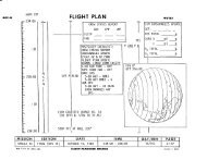
Spacecraft; weight is plotted against characteristic<br />
velocity for nominal and minimum values of specific impulse.<br />
(see figure 4-20. ) A sample path traces a typical solution for<br />
propellant weight when initial weight, specific impulse, and<br />
characteristic velocity change are given. Arrows on the chart,<br />
starting with an initial value for weight (W1) indicate the<br />
direction of flow for the sample problem. It is important to<br />
note that the characteristic velocity (Vc) scale does not<br />
represent values of AV remaining aboard the SIC, but is<br />
intended to serve as a reference only on which increments<br />
( AVC) may be taken as shorn in the sample.<br />
In order to account for a 4500 pound-seconds loss for each<br />
SPS engine start, 14.5 pounds cf propellant, must be added to the<br />
N/A<br />
CONSUMABLE REQUIREMENTS<br />
l2 1966 - -- . -Revision Date . .. - Page - 4-27
SMZA- 03-SC012<br />
APOLLO OPERATIONS HANDBOOK<br />
PERFORMANCE<br />
NOMINAL I OFF-NOMINAL<br />
Vg 24,216 FPS 24, 216 FPS<br />
Ys -1.65 DEG I -1.65 DEG<br />
U 156 DEG 156 DEG<br />
@ 0 DEG 6 DEG<br />
#EN ODEG 0 6EG<br />
C ~ O -o.om DEG - o . m<br />
GUST NONE HALF SINE WAVE<br />
0 52.7 DEG 52.7 DEG<br />
RANGE 1547 Ni4 1547 NM<br />
Fig-ire ii- l J. C/b! PCS PPapC11sn.1 Consu?.pt ion<br />
Tina i;ist.orfes - Singre Syster~<br />
Sfl-2AalOgj
!<br />
]<br />
!<br />
I<br />
|<br />
I<br />
I<br />
I<br />
I<br />
I<br />
I<br />
I<br />
I<br />
I<br />
1<br />
r<br />
I<br />
.... [ ....<br />
3:<br />
x:<br />
o_<br />
LU<br />
_J<br />
u<br />
36OO<br />
34OOO<br />
32OOO<br />
SMZA-03-SC01 g<br />
APOLLO OPERATIONS HANDBOOK<br />
PERFORMANCE<br />
GIVEN: INITIAL SPACECRA_ WEIGHT, Wl<br />
SPECIFIC IMPULSE, ISP<br />
CHARACTERISTICVELOCITY<br />
CHANGE, AVe<br />
g - 32.174 FT_SEC2 j. 1 1<br />
,,o,,_.w.o..,w_°w, i__-_ I<br />
Figure h-20. SPS Propellant COnsumptlOn<br />
6(;OO<br />
....... I........... I_ i ............. I<br />
C0tlSUMABEEBEg,UIR_ENTS<br />
SM-ZA-1094<br />
Ba, ic Date_ --12 Nov _-966 " Ret-_._ion Date ....... Page ...... ,-_r'_9 ...........
Consu.mables<br />
Hydrogen (_)<br />
(supercritical gas)<br />
Oxygen (02)<br />
(sucercritica! gas)<br />
Nitrogen (N2)(fuel<br />
cell reference<br />
_ressure)<br />
Basic Date. _"__'" "<br />
5MZA-03-SC012<br />
APOLLO OPERATIONS HANDBOOK<br />
propellant consumption noted during each firing. (The total<br />
propellant requirements are limited to the total usable<br />
propellants available to the S/C.)<br />
EPS AND EC$ CONSU._PTION DATA•<br />
Gxygen and hydrogen reactants (from the cryogenic Storage<br />
system) are consumed by the EPS fuel cell power plants in the<br />
generation of electrical mower, for the S/C. Water, as a<br />
byproduct, is provided for the ECS. Oxygen from the cryogenic<br />
storage system is also supplied to the ECS for metabolic con-<br />
sumption by the cre_emters and for pressurization of the crew<br />
compartment and the PGA. Vhe cryogenic tanks for oxygen and<br />
hydrogen are initially filiei to at least 97 percent of full<br />
capacitr. Nominal values for these consumables are as follows:<br />
Storage<br />
2<br />
Wci_?:t 9._r lank<br />
"Filled [!sable<br />
(!b ) ( ib )<br />
29 • _-' 28. 0<br />
327.? 320.0<br />
O. LL 0.4 h<br />
Flow Rate<br />
to System<br />
O.lh Ib/hr (min)<br />
0.27 ib/hr (max)<br />
(0.75 lb/hr-purge only)<br />
1.70 ib/hr (min)<br />
2.58 ib/hr (max)<br />
(0.6 ib/hr-purge only)<br />
N/A<br />
NOTE Both the EPS and ECS utilize oxygen from<br />
the sane cryogenic storage system (489 pounds<br />
of usable 02 for the EPS and 151 pounds for the<br />
ECS).<br />
EP2 Fuel Cell Reactants Consumption.<br />
The 02 and H 2 cons,&mption versus electrical output for<br />
one, two, or three fuel cell power plants is shown in<br />
figure h-2[. Only the }{o curve is given. (The 02 consumption<br />
rate is eight times the H2 rate.) Water generated by the 1_el<br />
c_lls nay be calculated by m,*It[plvinm the H 2 cons,_mption<br />
rat_ by nine. " -<br />
_O_,,b2,'IAzLa _.EQUI_E2,:£:[T?.<br />
_Revision Date<br />
Page Lt3)<br />
i<br />
T<br />
- i
",,,<br />
I APOLLO SMZA-' OPERATIONS 03-SC01Z HANDBOOK<br />
I PERFORMANCE , _ i<br />
I NOTE:<br />
WATER GENERATION RATE IS<br />
OBTAINED BY MULTIPI.YING H2<br />
I CONSUMPTION RATEBY NINE ,<br />
0.40 I::_'",!_' ::::,:_ :_:.:..:,_i_, I:_'t:,_r":I_.'_.' $':_ ::t:':'li_|'.:_J_l_'_<br />
3.20 -- _!_ _',_<br />
t'.:!:l'_!i:_: ....... :<br />
_'.'_._._, _-.-._" 3 FUEL CELLS_A_<br />
: '_:_!!|:' . .: ._...! ,.', ...... : l'.i_i_ _"I ......... ,I • r_: _._L_=,_:!!:_:_<br />
35 "" [_ -_ _ '._'_:' "':'_ '-,'I.' ;:}': :_: :, . ,._.'t.-<br />
2._o- _ .,..:._ .-i. _.,. . ,., _,. •,-,.=:,-: _., ..... _ ._._. ,___ :_ : :,_ _ _|:<br />
0.25 :i.', _'_'*"i "i_':_" • _:,. ,_ :T _i:i:-_",' ': '<br />
_ _ _!_ _ iF_EL_'-'CEL''''"[_ 2<br />
_<br />
I s 0.40 -- _!_._._i__1_:_+_l.."ai':_:ii'i<br />
r,_ -_Bi: !. ,, ._.._!:._.LE-_: _, '/..:'..._. li.i@.'il _ J.......... TYPICAL MMDB IN _o,_,,o_<br />
I 0- u_---_ 70 80 90 100 110 120 130 140 150<br />
3 FUELCELLCURRENT (AMPERES)<br />
I I l I. I l- Ir I _1 I I- J<br />
i 50 55 60 65 70 75 80 85 90 95 100<br />
2 FUEL CELL CURRENT (AMPERES)<br />
I 1 L I_ I I, I, I : i, k<br />
I 15 20 25 30 35 40 45 50 55 60 65<br />
1 FUEL CELL CURRENT (AMPERES)<br />
I<br />
I<br />
I<br />
I<br />
I<br />
Figure _-21. Cryogenic Consumption Versus Fuel Cell Current<br />
in order to maintain fuel cell operating efficiency,<br />
Basic Date- _2 Nov 19§_-.Revision Date-_-<br />
]<br />
SM-2A- 1095<br />
purging of each _ower plant is accomplished every 7 hourS. The<br />
purges will normally be staggered so that a H 2 purge will follow<br />
an 02 purge by _.5 hours. The present purging cycle Of 7 hours<br />
is based upon the maximum normal power output of 1420 watts per<br />
fuel cell. Th_ time between purges is based upon the ratio of<br />
the pre_ent maximum of 1420 watts/fuel cell power plant to the<br />
actual maximum gross power demand times 7 hours. Thus, if the<br />
actual maximum gross power demand is 710 watts/fuel cell<br />
module, the nominal purge interval of 7 hours would be increased<br />
by 1420/710 or 2. Multiplying 2 times 7 would then provide a<br />
purge interval of 14 hours, During purging, the power plant<br />
continues to consume reactants in the quantities required to<br />
produce the power demanded by Z/C electrical loads. The<br />
duration of each H 2 purge is 80 seconds and 120 seconds for<br />
each 0 2 purge .................<br />
CONSUMABLE REQUiREME_S<br />
...... Page .... _-2L .......
xygen (02 )<br />
smza-o3-scolz OF<br />
APOLLO OPERATIONS HANDBOOK<br />
PERFOE_ANCE<br />
EPS Electrical Power Cutout.<br />
r-<br />
During a normal mission, #rom launch until entry, AboUt<br />
618 kwh of electrical pOWer is supplied to the S/C by three<br />
Dael cell cower plants operating i_ parallel, if one power<br />
plant should fail, the remaining two will provide for normal<br />
power loads. In the event two power plants fail, S/C<br />
emergency loads can be acco_r.odated. The _hree batteries,<br />
no_ally reserved for entry and postlanding phases of the<br />
mission, can be utilized to provide for peak loads above<br />
operating fuel cell capacities.<br />
ECS Oxygen and Water Ccns'&_$tion 2<br />
'_::t' ihin,- an er.ercency po:,,er loud<br />
' el cell o[er'.tin:" durinc orbit.<br />
Oxygen and water co:.s,zmables are utilized by the ECS in<br />
providing for needs _q:_i[ar to th_ presence of men aboard the<br />
s=acecraft. , "" ,,c..... _" _a_ r',lues for the ECS consumables are as follows:<br />
Source<br />
Cryogenic storage<br />
system tanks (2)•<br />
NOTE The cryogenic<br />
storage sys_e., * su_-<br />
plies 0 2 to both the<br />
ECS and EF2 (!51<br />
pounds for th_ ECC<br />
and 489 pcund_ for<br />
the _oc_<br />
Usable<br />
Weight<br />
(lb)<br />
151.0<br />
Remarks<br />
The basic purpose of the<br />
ECS oxygen is for crew<br />
metabolic consumption<br />
and control of the C/M<br />
_ressure as follows:<br />
b •<br />
Metaboli_ - three me<br />
at 0.0_5 lb/hr/man c<br />
0.225 ib/hr total
I<br />
i<br />
I<br />
I<br />
I<br />
I<br />
I<br />
I<br />
I<br />
I<br />
I<br />
I<br />
I<br />
I<br />
!<br />
]<br />
l<br />
F<br />
Consumable s<br />
Potable water<br />
Waste water<br />
Nitrogen (N 2)<br />
(pressurant)<br />
i mT<br />
- T---I 1 ] .................<br />
SM2A-03-SC01 Z.<br />
APOLLO OPERATIONS HANDBOOK<br />
Source<br />
Surge tank<br />
Entry tank<br />
One C/M potable water<br />
supply tank<br />
One C/M waste water<br />
supply tank<br />
Two S/M water<br />
supply tanks<br />
One N 2 supply tank<br />
PERFORMANCE<br />
Usable<br />
Weight<br />
(ib)<br />
3.7<br />
1.0<br />
36.0<br />
56.0<br />
112.0<br />
1.5<br />
I " i<br />
Remarks<br />
c. 2 C/M<br />
repressurizations -<br />
11.7 lb (5.85 lb/ea).<br />
Initially filled during<br />
ground service<br />
Initially filled during<br />
ground service<br />
Initially filled during<br />
ground service; the tank<br />
is replenished during<br />
flight by the EPS fuel<br />
cell power plants at a<br />
nominal rate of 0.77 lb<br />
per kilowatt. If tank is<br />
full, water will overflo_<br />
into C/M waste water tan_.<br />
Initially filled during<br />
ground service and then<br />
by overflow of water<br />
from p5table water tank.<br />
Additional supply of<br />
water is carried in S/M<br />
to replenish C/M water<br />
tanks, if necessary.<br />
Used to pressurize the<br />
S/M water supply tanks_<br />
NOTE The ECS potable water will be primarily used for<br />
metabolic purposes by the crew and not for cooling<br />
purposes in the S/C (unless waste water becomes<br />
depleted).<br />
• The ECS radiator inlet temperature is afgected by heat<br />
transfer from EPS components, As the components become<br />
warmer from increased electrical loads, a greater rate<br />
of heat transfer will take place. ECS radiator freezing<br />
may result if both radiators are exposed to deep space for<br />
more than i hour and the inlet temperature is below 75"F<br />
CONSUMABLE REQUIR_4ENTS<br />
Basic Date. 12 Nov 1966Revision Date ,Page , _-33
4 .£.2<br />
_M2A-03-SC012<br />
APOLLO OPERATIONS HANDBOOK<br />
PERFORMkNCE<br />
_ith an e!ectricul current level of ::bout 55 :_mps By<br />
rolling or tumbling the S/C, to allo_, for periodic exposure<br />
of the radiators to the sun, the inlet temperature can be<br />
70°F _ith an electrical current level of about 50 :imps<br />
before the space r_6iators start to freeze.<br />
RCS AND SPS THRUSTING DATA.<br />
RCS TRANSLATION CONTROL.<br />
0<br />
Spacecraft translation is possible at any time after S-IVB<br />
separation and prior to the time when S/M-C/M separation occurs.<br />
Translation maneuvers are provided through the S/M RCS engines<br />
andare normally initiated manually b_ the translation control<br />
T-handle in the ±X, Y, and Z axes, or by the DIRECT ULLAGE switch<br />
in the +X axis. The translation control (manipulated in the<br />
counterclock_.:ise position to the abort detent for about 2.5<br />
seconds) also providez for CSM/S-IVB separation. "While the<br />
control is in the abort detent position, the CSM attitude is not<br />
controlled. Upon.confirmati6n of physical separation, the translation<br />
control is moved to the.÷X position and the SCS initiates<br />
attitude control to a mazim_m deadband o£ 5 degrees.. (R.,fer to<br />
section 2 for systems operation.)<br />
NOTE Each S/M RCS engine nominally develops i00 pounds<br />
of thrust. If four engines are ignited (as in u iX<br />
translation), the S/C v;ill accelerate _t 0.4 to 0.8<br />
ft/sec2, depending on the S/C v_eight ',ridcontrol mode.<br />
(0nly two engines are ignited for ±Y and ±Z translations.)<br />
The minimtur, RCS impulse duration, assuming _verage human-<br />
response, is on the order of 200 milliseconds. The maximum<br />
translation duration is a function of the uvailzble<br />
propellant.<br />
RCS ROTATION C@_TROL.<br />
Automatic or manual rotational control of the S/C is pro-<br />
vided in both the G&_; and the SCS control modes. (Refer to<br />
section 2 for systems operation.)<br />
NOTE TLe S/C can !rye a ma:
I<br />
I<br />
I<br />
I<br />
I<br />
I<br />
I<br />
I<br />
I<br />
I<br />
I<br />
I<br />
I<br />
I<br />
]<br />
[<br />
j-<br />
4.3.2.1<br />
4.3.2.2<br />
4.3 ._-3<br />
SMZA-03-SC012<br />
APOLLO OPERATIONS HANDBOOK<br />
G&N Attitude COntrol.<br />
PERFORMANCE<br />
During the G&.N &ttitude control mode, the inertial measurement<br />
unit (IMU) maintains the primary inertial attitude reference<br />
for the S/C. Rotation changes are commanded by either the <strong>Apollo</strong><br />
guidance computer (AGC) when verb 70 is entered in the S/C display<br />
keyboard (DSKY) for manual maneuvers with the rotation control,<br />
or by manually dialing the coupling display units (CDU) for<br />
maneuvers preprogrannned in the AGC.<br />
NOTE The AGC can be prograEmed to command a threeaxis<br />
60-degree reorientation of the S/C (and is<br />
similar in operation to an attitude orientation<br />
maneuver for an IMU alignment).<br />
All preprogrammed AGC maneuvers are executed at an<br />
attitude rate of 0.5 degree per second (4.0 degrees<br />
per second for abort or entry maneuvers.only). In<br />
the G&Nmode, a ±4.2 degree maximum or a ±0.2 degree<br />
minimum attitude error deadband is available The S/C<br />
will have a limit cycle rate of less than 0.2 degree<br />
per second within these deadbands.<br />
G&N attitude maneuver rates (used for IMU fine<br />
alignments.and checks) are limited by the G&.N<br />
digital program to 0.5 degree per second in<br />
pitch, roll, and ya_.<br />
SCS Attitude Control.<br />
During the SCS attitude control mode, the body mounted<br />
attitude gyros (BMAG) provide an automatic reference for holding<br />
the S/C at a specific attitude within a ±4 2 degrees maximum<br />
or a ±0.2 degree minimum attitude error deadband. If the S/C is<br />
then maneuvezed manually by the rotation control, the attitude<br />
gyro coupling unit (AGCU) will automatically cage the attitude<br />
gyros, correct the attitude hold reference, and present a new<br />
display on the FDAI when the maneuver is completed.<br />
Manual Attitude Control.<br />
Manual maneuvers for attitude control of the S/C are<br />
provided by use of the rotation control for direct and proportional<br />
rates, and by the attitude impulse control for<br />
low-rotational rates (minim_r, impulse). The primary<br />
RCS A_D SIS THEUSTDiG DATA<br />
Basic Date 12 Nov L766 ....Revision Date ................... Page-__- 4-_5 .......
SMa:\-03-SC01Z<br />
APOLLO OPERATIONS HANDBOOK<br />
purpose of the manual attitude controls "md pertinent data<br />
are as follo_.;s:<br />
i° Direct rotation control, for emergency and backup con-<br />
ditions, is commanded by use of the rotation control<br />
(stick) about the desired axes to its hard stops. Just<br />
before engaging the hardstops, a s_itch closes and applies<br />
a direct command to the RCS direct coils. Rate feedback<br />
is not used to cancel the stick movement, but the<br />
BMAG-AGCU loop is closed and maintains an attitude<br />
reference to its limits.<br />
NOTE The attitude rate,_commanded by direct rotation,<br />
is limited only by human endurance and the RCS propellant<br />
supply. Start and stop transients depend on pilot<br />
technique and the attitude reference (FDAI or visual<br />
!andmark) used to close +he outer control loop. The<br />
inertial references start to accumulate error (due to<br />
gyro slue rate limitations) at a rate of 20 degrees<br />
per second about the roll _xis and 5.0 degrees per<br />
second about the pitch or yaw axis.<br />
. Proportional rotation control_ for attitude corrections,<br />
is commanded by displacement of the manual S/C rotation<br />
control (stick) into a desired proportional rate (_hen<br />
referring to S/C attitude display on the FDAI).<br />
NOTE The resulting proportional rate will vary from<br />
a minimum of 0.2 degree per second to a maximum of<br />
0.65 degree per second (depending on stick dis_ldce-<br />
ment). Attitude error deadbands are ±4.2 degrees<br />
maximum _nd ±0.2 decree _inimum.<br />
Attitude impulse control, for co.._manding low-rotational<br />
rates about all three axes, is available in either G&N<br />
or SCS modes of operation and is used as required during<br />
navigational sighting periods. This is accomplished<br />
through the attitude impulse control located on panel<br />
!05.<br />
NOTE After the _ttitude impulse control is enabled<br />
an_ disp!uced, u s_itch closure in the control unit<br />
vlill cause one pulse of 18±4 _illiseconds, which is<br />
_pplied to the RCS jet selection logic. (One pulse<br />
is generated for e_ch uttitude impulse switch<br />
closure.)<br />
Basic Date 1_2 i;o'.- i766<br />
RC,C .2_', gF2 THRUST!I. _] EAT,.\<br />
Revision D_tte Page _6<br />
]<br />
I<br />
I<br />
I<br />
I<br />
I<br />
I<br />
I<br />
I<br />
I<br />
l<br />
[
I<br />
I<br />
I<br />
I<br />
I<br />
I<br />
I<br />
I<br />
I<br />
I<br />
I<br />
I<br />
I<br />
Basic Date 12 Nov 1966<br />
SMZA- 03-SC01 ?<br />
APOLLO OPERATIONS HANDBOOK<br />
PERFORMANCE<br />
AttitUde impulse control is not a proportional control<br />
and does not provide fer attitude hold. When<br />
this control is enabled, relay action remows all<br />
rate attitude error and control inputs from the SCS<br />
electronics.<br />
• Use of minimum impulse (for fine adjustment of S/C<br />
attitude) excites rates of about O.O1 degree per<br />
second minimum t0 0.5 degree per second maximum.<br />
SPS ENGINE THRUST PERFORF_gNCE.<br />
SPS Small-Impulse Operation.<br />
The SPS engine is capable of accepting a shutdown signal<br />
at any time after receipt of a start signal. .A nominal minimum<br />
impulse bit of 12,000 pound-seconds is developed _hen the<br />
engine is fired for an open-loop operation period of 0.6<br />
seconds. (See figure 4-22.) The run-to-run minimum impuLse-bit<br />
tolerance is ±300 pound-seconds (1 sigma). Impulse value as a<br />
function of start-to-shutdown signal duration (FS1 to FS2), is<br />
estimated from qualification tests generated at AEDC (Arnold<br />
Engineering Development Center). (Propellant consumption for<br />
small impulse firings including the 14.4-pound propellant loss<br />
for each SPS engine start is covered by the equation<br />
Wp = (Impulse +4500)/Isp.<br />
SPS Engine Start and Shutdown Transients.<br />
The SPS engine start and shutdown transients are presented<br />
in figure 4-23. Curves show the percentage of rated thrust as a<br />
function of elapsed time from start (FS!) and shutdown (FS2)<br />
command signals. Rated thrust is based on nominal inlet condition.<br />
All data estimates are from AEDC qualification tests. The start<br />
transient total impulse from FSI to 90-percent rated thrust is<br />
limited to the range from lO0 pound-seconds (minimum) to<br />
400 pound-seconds (maximum). The .run-to-run tolerance on start<br />
transient impulse is ±lO0 pound-seconds (1 sigma). The shutdown<br />
impulse from FS2 to 10-percent rated thrust is limited to a<br />
range from 8000 pound-seconds (minimum) to 12,000 pound-seconds<br />
(maximum). The run-to-run tolerance on the shutdown impulse is<br />
Z300 pound-seconds (1 sigma).<br />
RCS AND SP$ THRUSTING DATA<br />
Revision Date<br />
Page 4-37
Z<br />
0<br />
L,,)<br />
uJ<br />
Z<br />
o<br />
Z<br />
I<br />
u_l<br />
,,J<br />
:D<br />
m<br />
4.3.3.3<br />
I_,3.3._<br />
24,000<br />
22,000<br />
20,000<br />
18,000<br />
16,000<br />
14,000<br />
12,000<br />
10,000<br />
8,000<br />
6,000<br />
4,000<br />
2,000<br />
SMZA-03-SC012<br />
APOLLO OPERATIONS HANDBOOK<br />
PERFORMANCE<br />
0.2 0.4 0.6<br />
• ,., I. ;1..:i<br />
RESULTSOF A SINGLE<br />
.:":ENGINE TESTAT AEDC :.3.<br />
F:T;!'
I<br />
I<br />
I<br />
I<br />
I<br />
I<br />
i<br />
I<br />
I<br />
I<br />
I<br />
I<br />
I<br />
I<br />
I<br />
!<br />
,[<br />
l<br />
T<br />
100<br />
SMZA-03-SC01!Z<br />
APOLLO OPER.ATZONS HANDBOOK<br />
PERFORMANCE<br />
0.8 1.0 1.2<br />
ELAPSEDTIME IN SECONDS<br />
Figure 4-23. SPS Engine Start and Shutdown Transients<br />
1.4 1.6 1.8<br />
SM*2A-1099<br />
flight by the amount of SPS fuel remaining aboard the spacecraft.<br />
(See figure14U25.) The ground controller will determine SPS<br />
engine gimbal angles if propellant leaks and/or other than<br />
nominal oxidizer to fuel ratios occur.<br />
S/C OPERATIONAL CONSTRAINTS AND LIMITATIONS.<br />
OPERATIONAL CONSTRAINTS.<br />
Attitude constraints are necessary to prevent excessive<br />
exposure of certain spacecraft surface features to solar heating,<br />
earth albedo, or deep space. These constraints are required to<br />
control temperatures for the ECS radiator inlet, S/M _CS engines,<br />
SPS propellant feedlines, and the heat shield.<br />
RCS AND SFS THRUSTING DATA-S/C OPERATIONAL CONSTRAINTS AND LIMITATIONS<br />
Basic Date. L2 Nov 1966 Revision Date Page ..... 4-_9<br />
| |
e<br />
3500<br />
.......... _......_.L : ---.k---.-]---.-i .... : ................. : ........ : •<br />
• , - i.., 4.,, : : : . . • ......<br />
• . , : , . , ./ : '<br />
3O00<br />
: : ' ! " ' _<br />
-f-'-'--r----------'_=_-'_:=_-'_:---'r-----=<br />
' ! _ _<br />
"---==_=.'-_:i'_:_:_::: .......<br />
'i : "<br />
_ ....<br />
.<br />
_ ......<br />
i "<br />
.<br />
i " _/:<br />
' " '2": .'"<br />
, " ':' " i<br />
"_ ..... _ " "-'T-, '<br />
• I . . ._.NOTE. THEDELTAV .. ' : . , : /" • , .<br />
: i • _ REMANINGDOESNOT _ ,., " " . / .......... ...i ..<br />
.'-'r-T-" -_ INCLUDESPSTAIL-OF_ : • /<br />
Z 2500<br />
O o.<br />
I<br />
o<br />
z<br />
SMZA-03-SC01Z<br />
APOLLO OPERATIONS HANDBOOK.<br />
PERFOP_.NCE ORIGINAL PAGE IS<br />
OF POOR QUALITY<br />
...... ' ' ' .....<br />
• " • ? " " I ....... . -" ..... . ........ t '" = ""<br />
"_" ..... !" ': _"'_ f- : t " ,.... '" ........... _ ,'<br />
!"_. "!" ' : OFAPP,OXI__T,LY13FPS.: " . ./ . " ..._.._. ,.. :"<br />
F- , , , /:: : ,<br />
• I • : i.. . ; . • '<br />
_" ..... ,.... _..... :.":-r'-_ _"-:-; ...... 7 ........... / "<br />
t... ..... '-. ; . .i . ...... : .. /<br />
_.+ .... _ ....._......... ! ........ , ....... . /:. ......... _ ,...<br />
L.-; ' ' ""-" ", ...... L --;" ....<br />
[4 .... 4-.-_--_<br />
: ' ' ' " X I" "' " " ; I ....<br />
.... ':.. _i. : ..... :... : /,<br />
.<br />
.. :...<br />
| : I • I _ ' ! : • ; " : / • . .<br />
Q<br />
t.--.-÷.-,-_..---_:-,i-_-_ .....-,--+ ...... :,-t-, :..... -._ : ....<br />
k ....i ....!_ .... : . , / " '<br />
F ]- .:........... t, '''t .... _ ; .... " _"<br />
L' " "<br />
,_ 1500<br />
-- _<br />
lJI I'-_-k ....... !_-T":- ........ _ "i--y:,<br />
I-_, _ . .1 . , . /. '.'<br />
' _ : " _ -<br />
' '<br />
k" . • i ......<br />
• , .<br />
:....i.....:" F:i ....... , "'/? i-- : ...... .<br />
": i ' i I : i " ' ' ' ,<br />
-.-: ......._...! .... _........ i<br />
i i I i "<br />
o Io_o 20oo 3O00 4OO0<br />
DELTAV REMAINING- FPS<br />
Figure _-24. SPS Delta V Remaining Versus<br />
Propellant Remaining<br />
, i i | i ,<br />
S/C OPERATIONAL CONSTRAINTS AND LIMITATIONS<br />
SM-2A-t I00A<br />
Basic Date 12 Nov 1066. Revision Da_e P_a_e , 4-40<br />
-T<br />
]<br />
]<br />
]
SM2A-03-SCQlZ<br />
APOLLO OPERATIONS HANDBOOK<br />
PERFORMANCE<br />
e/c OPERATIONAL CONSTRAINTS m-b LIMITATIONS<br />
Basic Date 12 Nov 1966 Revision Date - Page 4-41<br />
0
SM2A-03-SC01Z<br />
APOLLO OPERATIONS HANDBOOK<br />
4.4.1.I ECS Radiator Inlet Temperature.<br />
PERFORY._NCE<br />
The ECS radiator inlet temperature (obtained from MSFN or<br />
the a_ciliary DC volts meter on panel 200) should be maintained<br />
at 75"F or warmer to prevent against radiator freezing. However,<br />
excessive water boiling will result if the radiators are directly<br />
exposed t6 the sun for prolonged periods. S/C orientations<br />
exposing the ECS radiator surface to solar incidence angles less<br />
than 45 degrees should not be maintained longer than 20 minutes<br />
per or_oit. Also, the S/C attitude should be constrained<br />
inertially or held fixed relative to the earth without roll for<br />
a period longer than one orbit, if the solar incidence to the<br />
radiator is less than 45 degrees. To prevent excessive water<br />
consumption (boiling) the S/C attitude must not be constrained<br />
in an inertial or earth-fixed orientation without roll for longer<br />
than 3 hours.<br />
CAUTION Extreme radiator sooting can be detected<br />
by a rapid depletion of the water supply<br />
and high radiator outlet temperature.<br />
• If the radiator outlet temperature averages above<br />
53@F as a result of extreme sooting, high electrical<br />
loads, or poor radiator orientation, the water tanks<br />
_ill be depleted at a rate incompatible with the<br />
planned mission duration time.<br />
NOTE Observance of ECS radiator constraints will als0<br />
ensure a satisfactory environment for EPS radiator<br />
operation.<br />
4.4.1.2 S/M RCS Engine Temperatures.<br />
The S/M RCS engines are qualified to work within the range<br />
of 35" to 175"F, the propellant valve temperature limits. A red<br />
warning light on panel l0 will illuminate to indicate when the<br />
temperatures exceed this r_nge. Temperatures above 175°F are<br />
not expected, except temporarily (possible) during boost.<br />
Heaters that cycle automatically are provided on each quad to<br />
maintain temperatures above the lower limit. However, if one<br />
quad is continuously pointed away from the sun for longer than<br />
I0 hours, it is possible for the h0"F lower temperature limit<br />
(for the propellant) to be reached at the RCS tank outlet.<br />
NOTE S/C attitude should be monitored during extended<br />
periodz between RCS firings to ensure that safe<br />
temperatures awe maintained.<br />
S/C OPE_ATIOItAL CONS'fI_._INTS AND LI_,'rTATIONS<br />
Basic Date_'L_ I;_v L'_6.. . Revision Date<br />
m_<br />
.L<br />
I<br />
i<br />
T<br />
as<br />
e ,
i<br />
I<br />
I<br />
I<br />
' I<br />
. I<br />
: i<br />
i '<br />
i ' i<br />
i<br />
I<br />
I<br />
I<br />
I<br />
I<br />
1<br />
r<br />
4.4.1.3<br />
4._ ,l.4<br />
4 ,_.2<br />
4.4,2, ]<br />
4.4,2.2<br />
SM2A-03-SC01 2<br />
APOLLO OPERATIONS HANDBOOK<br />
PERFORMANCE<br />
BPS Propellant Feedllne Temperatures.<br />
SPS propellant feedllnes are normally maintained above<br />
h0"F by heaters and insulation. The MSFN should monitor SPS<br />
external line temperatures and advise the crew whenever<br />
temperatures drop below 50°F. If S/C attitude iS maintained<br />
so that the SPS is pointed away from the sun for an extended<br />
period and heater capacity is insufficient to maintain llne<br />
temperatures above h0"F, the S/C should be reoriented until<br />
acceptable SPS line temperatures are reached.<br />
Heat Shield Temperature.<br />
The heat shield ablator lower temperature limit of -150°F<br />
can be exceeded and cause surface cracking if the thin (-Z)<br />
portion of the ablator is pointed away from the sun for longer<br />
than 3 hours. Because of the moderate response time, it is<br />
unlikely that a critical cold condition would be approached<br />
during the mission.<br />
CAUTION If the heat shield ablator temperature<br />
is allowed to rise and remain above 200@F<br />
for any aggregate period longer than 2 hours, outgassing<br />
will result and cause a corresponding degradation to the<br />
ablator stress margin.<br />
OPERATIONAL LIMITATIONS.<br />
The available data in the subsequent paragraphs shows<br />
limitations imposed on the S/C and/or crew during ascent, descent<br />
or aborts, spaceflight, and entry.<br />
Acoustic and Vibration Effects.<br />
The crew will be exposed to acoustic and vibration effects<br />
during ascent (130 seconds), possible LES aborts (20 seconds),<br />
and entry (i00 seconds)_ Vibration effects will also be<br />
experlenced during hlgh-altltude aborts (SPS induced) and<br />
spaceflight SPS firings, (See figures 4-26 and 4-27.)<br />
Altimeter Error and C/M Base Pressure Effects.<br />
The altimeter (barometric pressure indicator) error resulting<br />
from veloclt_ pressures on the co_u-mand module (below<br />
iI_,000 feet) is shown in figure ' ._,_<br />
C/M Llft/Dra_ Profile and Entry Effects.<br />
Charts showin_ the C/M li#t/drag profile iuid time histories<br />
for. normal.entrles _.e showu In figures i-2_ thr,A,_h l,.j[ .......<br />
S/C OPERATIONAL CONSTRAIntS AND LIMITATIONS<br />
Basi_ Date .k2 N.'v..l_66 .-_Revtsion Date,.,- ........<br />
-i-Pag_ .... !,=I,_..
7O<br />
SS db<br />
79 db<br />
120 db<br />
140 db<br />
160 db<br />
_0 db<br />
SMZA-03-5C01 2<br />
APOLLO OPERATIONS HANDBOOI(<br />
PERFOBMANCE<br />
CREW COMPARTMENT NOISE SPECTRA<br />
0 16 32 63 125 250 500 10O0 2000 _ 8000<br />
AVERAGE OCTAVE BAND FREQUENCIE_- CPS<br />
= Sound i_euuie level _PLI under av_age office conditiont,<br />
= MO_imumSPLintide SIC- during tl_Ce fl;ght with all Muipment operating,<br />
NOTES, I OustingtpaCe flight. CI M intide noise<br />
level it mainly due _ equil_ n_nt OlN1'ation.<br />
SPSand R¢S enqine firings have Idtle<br />
effect c_ the internal Use level.<br />
2 Each astronaut con tecl_cethe crew compartment<br />
nolte level about 15 db by utilizing his Sl_e<br />
suitond closingI!_ helmQt vi_x.<br />
- _ where d,lcomE_rtis elpeqrienc_l.<br />
= _ where i_,n is e_o_nte_ed<br />
_--_beILwhere the human eat drum can be _l_Vted<br />
_- _ eqeivoten, _o a tGpovnd TNt bi_e at 10 feet<br />
Pisure _ -."_. C/H Cri;v Compartment Acoustics<br />
SIC OPEPJ_TION/_LCON_J_AtNT_ ANb [,IN_TATIONS<br />
BmsiC Date -_" _; "" t)_,, ,-_Rev_ion Date ........... Page<br />
i<br />
rl<br />
_.2A,9241<br />
[+-ltl f .....<br />
,i<br />
l<br />
l<br />
I<br />
I<br />
I<br />
l<br />
i<br />
I<br />
I<br />
I<br />
I<br />
I<br />
I<br />
I<br />
l<br />
l
I<br />
i<br />
1<br />
t<br />
I<br />
I<br />
i ,___<br />
O_O<br />
iii/-tll i_,_l_t.INit ._li_+el,;1:1l-1liil_<br />
I_i _'1_;1_I1 _1 tt: I _: I I=LLII" L I=III_;<br />
_<br />
SM_-A-03-SCOXZ<br />
APOLLO OPERATION5 HANDBOOK<br />
PERFORMANCE<br />
ATMOSPHERIC hIGHT REGIONS<br />
_+t,_t++t__..+_<br />
_!!-ililitf';!i!tii ;:".-I_iM",_lI!<br />
. 7O 80 _ I@,<br />
110 120 130+ 140<br />
TIME FROM LIFTOI:F |SECONDII<br />
_.;.._+,_..+I!+iii_<br />
_"_i_.%!;_I+.!_<br />
'*. _++: ,..... fill_" _l t._' .I .,++ ,+It tit"'_'.!.i+ .,.? ,&. ..l :i; . .. _<br />
_,+I .,.I.+.g,,++_,,.l,+,l,. _+_<br />
: + +.,_,+,I,_.+,h,+P;,+,l,+,+,+_l<br />
"iS: .... {+'++:_+++::+ l+ _ I_ +:+i .t +l: + , .... :" ,<br />
_%_+_I_,_@++tIMtliii+l+Ii._.l<br />
!l<br />
• +,+ + ; 'i++;_-_' _.+l:: :R_ !li. + ,:;_::..<br />
NOTES: I, Zero on the vertical' scale indicates the moxlml+m vi_otioa eXl_llriencld during flight. The vi_et+o_ levels<br />
Oil bol41d o!,1 boilerplote and spacecraft fiighi test m_osCrwments.<br />
2. Ltltlr "A" indicates vibrotlon tint inducld by b
IK<br />
0 IK 2K<br />
I<br />
SM2A-03-SC012<br />
APOLLO OPERATIONS HANDBOOK<br />
: ' -i.. r '"<br />
!<br />
PLANNED ALTI/VLETER : !.<br />
MARKER SETTING<br />
PERFORMANCE<br />
....... Figur_ I,,28. Altimeter. Error and C/M Base Pressure. Effects<br />
S_A.rJ_A<br />
BltiC Date _2<br />
S/C OPERATIONAL<br />
li_','. _q6<br />
CO_STRAIh_TS AND LIMITATIONS<br />
"_,r6- IRevision Oizte, -° .- Daze , _ .h-._6<br />
[_<br />
. .<br />
QIF<br />
I<br />
I
i<br />
i<br />
I<br />
[,<br />
I<br />
l<br />
SM2A- 03-SC012<br />
APOLLO OPERATIONS HANDBOOK •<br />
"1....<br />
PERFORMANCE<br />
i<br />
I<br />
!<br />
I<br />
...... r ...... i - 7 ..... - -<br />
SiC OPERATIONAL CONSTRAINT_ AND LIMITATIONS -<br />
Balic Date _2 N_;v L,.:_oO__.Revision Date, -- . - _Page-- . _li-li_<br />
p,-<br />
,-4<br />
,el<br />
,i-I<br />
O<br />
I<br />
O,i.<br />
I<br />
-,1"<br />
II<br />
°el
SMZA-03-SC01Z<br />
APOLLO OPERATIONS HANDBOOE<br />
PERFOI_MANCE<br />
O<br />
0<br />
0<br />
m"<br />
0<br />
I<br />
_b<br />
et<br />
•<br />
/<br />
.=
1<br />
t<br />
I<br />
I<br />
I<br />
II .... rr-<br />
SM2A-03-SC012<br />
APOLLO OPERATIONS HANDBOOK<br />
...... I ...... I - - "i - - - ] I T I II "<br />
S/C OPERATIONAL C0NSTKAiNTS AND LIMITATIONS<br />
Baii¢ Date 12 Nov i966_._,Revisio n Date ............ Page<br />
+<br />
O<br />
4_ ¢0<br />
.el<br />
Q)<br />
.r.4<br />
,'-4<br />
I<br />
,-d<br />
¢d<br />
o_<br />
==<br />
0'3 L<br />
.._-~<br />
.,'4
..<br />
l<br />
(<br />
L<br />
i<br />
!<br />
I<br />
I<br />
1<br />
)<br />
i<br />
I<br />
I<br />
i<br />
Mission<br />
SMZA-03-SC01Z<br />
APOLLO OPEI_ATIONS HANDBOOK<br />
EXPERIMENTS AND SCIENTIFIC EQUIPMENT DATA<br />
SECTION 5<br />
EXPERIMENTS AND SCIENTIFIC EQUIPMENT DATA<br />
INTRODUCTION<br />
This section presents the objectives of mission Z04A experiments and<br />
Contains a description of associated equipment, stowage areas (figure 5-I),<br />
crew participation requirements for data collection, and related scientific<br />
equipment data. The in-flight tests are categorized as medical (M-), scien-<br />
tific (S-), and technical (T-) experiments as follows:<br />
• In-Flight Exerciser (M-3A) (M003)<br />
• In-Flight Phonocardiogram (M-4A) (M004)<br />
• Bone Demineralization (M-6A) (M006)<br />
• Human Otolith Function (Vestibular Effects)(_Vi-9A) (M009)<br />
• Cytogenetic Blood Studies (M-II) (M011)<br />
• Cardiovascular Reflex Conditioning (M-48) (M048)<br />
• Synoptic Terrain Photography (S-bA) (S005)<br />
• Synoptic Weather Photography (S-6A) (S006)<br />
• In-Flight Nephelometer (T-3) (T003).<br />
NOT_ The planning and Management Office of the EPO<br />
(Experiments Program Office) is the coordinating facil-<br />
ity for all of the experiments described in this section.<br />
The experiments sto_.vage areas location will be found in {igure 5-i.<br />
SCIENTIFIC EQUIPMENT..<br />
MEDICAL DATA ACQUISITIO -_: SYSTEM (MDAS).<br />
The medical data acquisition system, located in compartment C<br />
(figure 5-Z), weighs 15.Z pounds and consists of a seven.channel tape<br />
recorder, associated signal conditioners, junction box, time code generator,<br />
and a front panel with switches and outlets for power and signal cables.<br />
This GFE unit uses Z8-volt d-c power from compartment A to acquire and<br />
permanently record on magnetic tape all required medical (operational and.<br />
experimental) data. The operational data.required consists of electro-<br />
cardiograph and impedance pneumograph outputs, while the experimental<br />
data consists onlyo{ phonocardiograph,outputs. These medical parameters<br />
are routed from sensors and signal conditioners (attached to a crewman)<br />
through the PGA or CWG adapter cable, cobra cable, T-adapter, and<br />
octopus cable to specified channels in the MDAS. Although I00 watts of<br />
'ectrical power is provided for the MDAS from compartment A via the<br />
:topus cable, only about 19 watts are needed to operate the integraltape<br />
"" i i- - 7r ..... i -- irl- ] 1 [ I<br />
SCIENTIFIC EQUIPMENT<br />
_ __.,, Basic Date 12 Nov - - 1.966 i "<br />
-Chan_e Date -, Page<br />
_-I
Mission<br />
SM_A-03-SC012<br />
APOLLO OPERATIONS HANDBOOK<br />
EXPERIMENTS AND SCIENTIFIC EQUIPMENT DATA<br />
SCIENTIFIC EQUIPME NT<br />
Basic DaCe ..l.Z_Nqv_!966 ChanRe Dale -
,,<br />
I .<br />
SMZA-03-SC0 |2<br />
APOLLO OPERATIONS HANDBOOK<br />
EXPEIR/MENTS AND SCIENTIFIG EQUIPMENT DATA<br />
in<br />
i i<br />
sCIENTIFIC EQUIF'MENT<br />
Mission _ ,Basic Date !2 Nov 1966 Change Date -<br />
_3<br />
iv"<br />
_ Page ..5-,3_,<br />
¢,,I<br />
N .<br />
Qa<br />
m<br />
[4 ,4<br />
.o<br />
U<br />
=<br />
M<br />
ua<br />
=<br />
.o<br />
N<br />
O<br />
O<br />
=
l%lission<br />
SMZA-03-SC01Z<br />
APOLLO OPERATIONS HANDBOOK<br />
EXPERIMENTS AND SCIENTIFIC EQUIPMENT DATA<br />
,, i<br />
COBRA T-ADAPTER<br />
ELECTRICAL<br />
(I<br />
OXYGEN<br />
CONNECTOR<br />
(LEFT<br />
I<br />
IMPEDANCE<br />
PNEUMOGRAPH,<br />
EKG, AND<br />
PHONOC<br />
OXYGEN<br />
UMBILICAL<br />
COBRA CAME<br />
(ELECTRICALUMBILICAL)<br />
CREWMAN/OXYGEN<br />
AND ELECTRICALUMBILICAL<br />
CONNECTORS (RIGHT AND<br />
CENTER CREWMAN)<br />
PGA<br />
ELECTRICAL<br />
ADAPTERCABLE<br />
FUTURE<br />
EXPERIMENT<br />
RECEPTACLES<br />
TIMER TAPEREC<br />
SWITCH TESTLIGHT<br />
(RECORDER) (RECORDER)<br />
A<br />
POWERRECEPTACLE<br />
I NST PWR<br />
(RECORDER)<br />
MAIN PWR<br />
\<br />
RECEPTACLE<br />
Figure S-Z, Experiments Tape Recorder and Electrical Connectors<br />
SCIENTIFIC EQUIPMENT<br />
:OMPARTMENT A (REF)<br />
MDAS PANEL<br />
(COMPARTMENT C)<br />
.Basic Date IZ Nov 1966 Chan_e Date, = , Pa_e 5-4<br />
.E<br />
iJ<br />
.!<br />
l<br />
I<br />
.t<br />
-?
4<br />
I<br />
!<br />
i<br />
I<br />
I<br />
i<br />
i .<br />
I<br />
I<br />
I<br />
I<br />
l<br />
5. 1.2.2<br />
I%lission<br />
SMZA-03-SC012<br />
APOLLO OPERATIONS HANDBOOK<br />
EXPERIMENTS AND SCIENTIFIC EQUIPMENT DATA<br />
m •<br />
i, _ i , i<br />
recorder. However, electrical outlets on the MDAS front panel are<br />
provided for additional or future experiments (via electrical cabling con-<br />
nected directly to the equipment and the MDAS). The MDAS front panel<br />
also contains a MAIN PWR switch for controiling power to th_ unit and unit<br />
outlets, an INSTR PWR switch for controlling p6wer to the tape recorder<br />
and the recorder test light, and a TIMER switch for correlating mission<br />
elapsed time.on the tape recorder.<br />
All three crewmembers have the capability of being recorded for their<br />
physiological data when electrically connected to the tape recorder. How.._<br />
ever, only one crewman at a time will have his outputs recorded during<br />
flight. (See figure 5-3.) Total recording time for the tape recorder is I00<br />
hours maximum with 880 feet of usable tape. There are seven channels<br />
available for collecting data (including the optional channel for recording<br />
code signals).<br />
The MDAS tape recorder is removed from the spacecraft immediately<br />
after flight, placed in a GFE metal container for protection against strong<br />
magnetic fields, and transported to the NASA-MSC (where the magnetic<br />
tap eis removed from the recorder).<br />
ELECTRICAL CABLES AND ADAPTERS.<br />
_OCto_us. Cable.<br />
The octopus cabh (figure 5-2) plugs into the MDAS tape recorder, is<br />
protected from electrical arcing by an on-off power switch on the recorder<br />
panel, and contains signal and power lines for the following:<br />
• Provides for Z8-volt d-c (i00 watts) power from compartment A to<br />
the MDAS in comp.artment C<br />
e<br />
Provides for biomedical signals from a crewman (attired in the PGA<br />
or CWG) to the tape recorder. These slgnals consist ofEKG, phono-<br />
cardiograph, and impedance pneumograph outputs. This cable weighs<br />
i. 5 pounds and is Stowed in compartment D of the LHFEB during<br />
hunch and entry. The cable remains connected to the MDAS and a<br />
crewman's T-adapter during orbital flight.<br />
Cobra Cable T-Adapte_r.<br />
The T-adapter (figure 5-2), provided for each crewmernber, weighs<br />
i/Z pound and remains attached to the cobra cable at all times. This three-<br />
way electrical connector mates the cobra cable to the appropriate crewman<br />
electrical umbilical connector (panels 300, 301, or 302) and the octopus<br />
cable. A relay incorporated in the T-adapter is controlled by the TLM<br />
INPUTS-BIOMED (MDC-20) or the MDAS MAIN PWR switch in compart.<br />
ment C (providing the octopus cable lead is connected to the T-adapter).<br />
This relay permits electrical signals, from a crewman,s torso, to be<br />
transmitted as operational data and recorded in-flight as experimental data.<br />
SCIENTIFIC EQUIPMENT<br />
_ Basic Date. 12 Nov 1966 Change Date_<br />
Page__ 5-5
l%_ssion<br />
SM2A-03-SC01Z<br />
APOLLO OPERATIONS HANDBO_)K<br />
EXPERIMENTS AND SCIENTIFIC EQUIPMENT DATA<br />
NON ESS BUS<br />
(MDC_22)<br />
OFF<br />
N N NT AL BI .--=,,o<br />
J SEB-I j SCIEN EQUIP. (MDC-22)<br />
I (MDC- 22)<br />
COMPARTMENT A I I COMPARTMENT B I Iur_O_<br />
28 VDC POWER I | (WIRING ONLY) J |<br />
t SOURCE J L--,,--......--I L.<br />
' SCIENTIFIC<br />
"_" 100 WATT EQUIPMENI_<br />
OUTLET (RH OUTLET<br />
COMPARTMENT C<br />
MEDICAL DATA<br />
ACQUISITION SYSTEM<br />
_. I \RECEPTACLES FOk<br />
PRESSUREGARMET _1 FUTUREEXPERIMENTS<br />
/ASSEMBLY(PGA) _ OCTOPUS CA,LE<br />
--'_''_-T4Z _" (CONNECTS T_MDAS<br />
.f,". "'_11. jPGA ELECTRICAL AND TO ONE T*ADAPTER<br />
l _!| _' '..,_Tll/l_ DEUTSCH , *<br />
I CONNECTOR<br />
.... CREWMAN 2 i_LEC UMB CO NN (PANEL 300)<br />
)11 co, cA, A CREWMAN E , LECUM,<br />
PANEL 207)<br />
%_ It T'ADA_PTER/,_J_ CREWMAN 3 ELEC UMBCONN (PANEL 302)<br />
NOTES:<br />
|. Signal wndit;onen, senlon, and associated 2.<br />
wiring on a crewman% t¢_o (attached to<br />
the M;cmd0t _nhectar inside the PGA or on<br />
the _'WG) provide fbr P_M TLM operational<br />
measurement1 and scientific ex_tr;ments d_ta,<br />
/M009<br />
/POWER<br />
CONN(PA EL 0,,<br />
SCIENTIFIC<br />
EQUIPMENT<br />
(LH OUTLET<br />
PANEL 318)<br />
CABLE<br />
CAMERA |<br />
(USES 20.3 WATTS) J<br />
)| 1 TO AUDIO CENTER FOR<br />
J PCM TLM OPERATIONAL<br />
)_. MEASUREMENTS-DEPENDING<br />
J ON POSITION OF TLM<br />
)/J INPUTS SWITCH ON MDC-20<br />
A T-adopter permits simultaneous tmn_n;.ion of<br />
opemtion_J me_ture_en_ (tele_,;ted for one crewman<br />
at a time) and the ra¢ordlng of in-flight experiments data.<br />
However, o_tion_J measurements can be transmitted<br />
from one crewman while another cteWmcln is recording<br />
expeti_ents datc_<br />
Figure 5-3. Scientific Equipn_ent Power Distribution<br />
SCIENTIFIC EQUIPMENT .<br />
SM-2A-_02C<br />
Z04A Basic Dart, 16 Se_._ 196,6,__ Chan a_ Date .. . ...... Pa=e 5-6<br />
ek<br />
_w<br />
-t<br />
ee
5,1.2,3<br />
5.124<br />
5,21.1<br />
SMZA-03-SC0tZ<br />
A P0 LLO OPERATIONS HANDBOOK<br />
EXI_ERIMENTS AND SCIENTIFIC EQUIPMENT DATA<br />
Oper'Ational data from one %rewman may also be ti-ansmitted while<br />
experi,nentM data from another Crewmat% iS being taped eli the MDAS.<br />
However, only o/xe operational trhnsn%issio/x atid one eRperithental record-<br />
ing can be taken at the s_me time.<br />
PGA and CWG Electrical Adapter Cables.<br />
The PGA and CWG electrical adapter cables (crew personal equip_<br />
ment) are provided to connect, the cobra cable to signal conditioners and<br />
communication equiptu.ent attached to a crewman's body. (See figure 5-3<br />
and refer to section 0.)<br />
Hardware Power and Sigt)al CablOs.<br />
Hardware power and signal cables are-used for connecting equipment<br />
electrically to. various outlets in the crew compartment. (See figure 5-3. )<br />
Protection from electrical arcing is provided by sxx:itches on the equipment<br />
or on the outlet panels in the crew cabin. The M-qA camera power cable<br />
(figure 5-3) connects to the Nit SCIENTIFIC-EQUIPMENT outlet on panel<br />
207. A SCIENTIFIC EQUIPMENT outlet on panel 318 (near the LIt side<br />
window) is reserved for a future experituent but can also be used a_ a<br />
backup outlet fur the camera cable. Outlets marked J102 through J105 on<br />
the MDAS are reserved for future experiments (See figure 5-2. )<br />
MEDICAL EXPERIMENTS.<br />
IN-FLIGHT EXERCISER (M-3A) (MOO3).<br />
The purpose of experiment M-3A. ig to coIlc,:t crew data for dOtOr-<br />
mining benefits of exercise during space flight. Recumbency (bed rest)<br />
studies have shown that exercise work _olerance for an individual is<br />
greatly reduced after, being relatively immobile and in a horizontal position<br />
for a few da.ys. Zero gravity during space flight may further increase the<br />
length of a c_e_iuan's reconditioning period.<br />
E_ipment l)esc riptio!_.<br />
The exerciser for experiment M-3A (figure 5-4)weighs about 1-1/2<br />
pounds and consists of two rubber elastic (bungee) cords with a retaining<br />
cable, A nylon elastic sleeve covers the bungee cords and retaining cable.<br />
One end of the exerciser contains a. looped straF rnade of webbittg cloth<br />
that can be _ecured around l crewman's feet. The other end of the<br />
exerciser has a spherical plastic handle grooved to fit both hands of a<br />
crown,an, The retaining or safer}- cable within the elastic slceve permits<br />
the exerciser to be stretched fron_ o, 1/2 to 21-I/_ inches.<br />
A mechanical interface bet_ oon the equipment and the S,/C exists<br />
where the" exerciser container is attached to the CO 2 absorber contait_er in<br />
the LEB (opp,_stto the RH couch). Although all three COliC|lOS Call be klsed<br />
sCIENTIFIC EXF'I.:RIMENTS- XIEDICAL F_XI'ERIMENTS<br />
B.lgtt Date ,1.2 Nov l_!.t_t, . t'h,'tn_e Date ,,.- - Page _-7
SMZA-0J-sC01Z<br />
APOLLO OP_RATIONS HANDBOOK<br />
EXPERIMENTS AND sCIENTIFIC EQUIPMENT DATA<br />
, i, r<br />
NOTE: M-3A _e_llo_ Is placod<br />
in I_1 and ota_chld to CO 2<br />
gbol_dgel ¢_htalnor _t<br />
I_w_le in LEO (omiite<br />
RH much).<br />
- - M-]A EXERCISER<br />
root suemet (CUTAWAYFOR CLARITY)<br />
ANO L[GRI[ST<br />
OOWN<br />
II I ......... I II El I II I I I I I I<br />
PLASTIC HANDLE<br />
Lg(PERIMENTS$-5A ANOS-Ok EXP[RIMENTT-3<br />
I_IOT[: All S-SA o*_d $:6A i_lrlment<br />
V|LCRO ,_ATI NG<br />
_u,l_t it It_gd in _rtmehtt<br />
A and g durlntl Jaunch .{<br />
"_,"_ _ _ LENS (FILTIII _.TT4CHEO)<br />
__ . _'$°_k FII.._ PACK (INI;RAR[O]<br />
S-_b_ tllJ_ PAC_ (llLACI_ kNO WHITE't<br />
/<br />
c.,,+,.. --/I<br />
NIOTt_ The nephile_etlt mutt he<br />
tetvehed te C_rtment<br />
| |go Itol_lll ehet i_¢h lilt<br />
ar_l_l,t, if ,i libel II¢_;de_l<br />
I1._ l,l'i_llnl Ill Volcm<br />
AIR PASSAG[ V[N]S<br />
(_USHIUTTON)<br />
Figure 5_-4. Experiments Oper&tiotlal Arrani(ement (Sheet I 6i 2)<br />
MEDICAL KX PF, I_ (MKNTS<br />
$,W. ;A _<br />
I_._,_ D,_tc IZ Nov 1.96.6 ('h,_n_e Date , V'a .__ _ -8<br />
BR<br />
]<br />
]<br />
]<br />
1
i<br />
!<br />
I<br />
1<br />
t<br />
t<br />
1<br />
I<br />
I<br />
r<br />
t<br />
EXPERIMENTM-gA<br />
SMZA-03-SC012<br />
APOLLO OPERATIONS HANDBOOK<br />
EXPERIMENTS AND SCIENTIFIC EQUIPMENT I_ATA<br />
ii<br />
i<br />
M-9A POWER OUTLET<br />
CON, OLd)_ • \ M._.llrA. I<br />
_MERAo. " " ' -"'_ _'-:-_'!' k_3;_._,.,ECEPTaCLE iWP,CAL<br />
/ .... :-..., .A_'I_/,.'%-<br />
ADJUSTABLE EYEPIECE _ " "' " -"_ '\ "; "" ' "" " "._''- __" ]'-"_ \ CAMERA<br />
(PITCH a ROLL PLANE) . . .,,:. , \ ",. ." ,' '-_,.'_ _ I _ x<br />
5. Z. 1.2<br />
Mission<br />
--.-7:;,".3.. ,_ - • ; /-<br />
_MOUTHPIECE AND SHA_<br />
M-gA GOGGLES<br />
Figure 5-4. Experiments Operational Arrangement (Sheet Z of 2)<br />
i<br />
,,M_-2A-865B<br />
during the M-3A isotonic and isometric exerciseS, only the center crouch<br />
provides adequate head room to conffortably perform isotonic exercises<br />
when data recording periods are conducted. (Date includes EKG, impedance<br />
pneumograph, and phonocardiograph recordings taped on the MDAS<br />
recorder. )<br />
Experiment Procedures.<br />
All crewmen will exercise in-flight for 10 nainut_s three times every<br />
Z4 hours. The base line preflight data will serve as a control for the study.<br />
A recording session is required once per day on one crewman before,<br />
during, and alter an exercise period. Crewmernbers will alternate each<br />
day for data recordings. (Detailed procedures are provided in section 11 )<br />
/<br />
MEDICAL EXPERIMENTS<br />
Basic Date 12 No_ 19.66._ .ChanRo Date- Page.
SMZA-0]-SC01.'<br />
APOLLO OPERATIONS HANDBOOK<br />
EXPERIMENTS AND SCIENTIFIC EQUIPMENT DATA<br />
5.2.1.3 Cr ewr_%an Ibar tlci_atiot%.<br />
Requirements for crewmat_ participation in the exercise experiment<br />
are as follo_vs:<br />
a. Prefl{ght - Each ¢re_vman will be tested for exercise tolerance<br />
(phySiCal fitneSS level) on thre6 separate occasions 8 to 4 weeks prior to<br />
flight.<br />
b. In-flight - Each crewt_aan will be required to exercise 3 th'ues daily<br />
for 10 minutes _ach excrcis_ period. Medical data front one crewman will<br />
be recorded during one exercise period each day. (It will tak0.3 days to<br />
obtainnxed[cal data from all three crexvmen. )<br />
c. Postflight - Each crewman will undergo re-evaluation exercises on<br />
three Separate occasions (12 to 24 hours, lweek, and 2 weeks after touchdown).<br />
5.2. 1.4 R ec over )" R equir Ct_xc.nts.<br />
There are no special recovery requirements for experitnent equipment<br />
because the in-flight exerciser will remain Stowed in the S/G durihg r_cov-<br />
cry. An exerciser of equivalent design will be available at the site where<br />
postflight evaluations are per_ortued and the experiment is completed The<br />
on-site coordhxators will be respo_tsible for removal of the magnetic record-<br />
ing tape from the P,LDAS and delivery of all data to the '.NTASAoI_ISC.<br />
_.2 2 IN-FLIGHT PHONOCARDIOGRA.M (M-dA) (M004).<br />
"_._.. 2.1<br />
,_t SS tot% ,<br />
The purpose of experiment kl-4A is to obtain information on the func =<br />
tional cardiac status of two cre_vtnan during prolonged space flight. An<br />
in-flight recording of the phonocardiographic heart sounds, compared with<br />
the highest EKG sign:xl, will be made to dotertuine the delta tirue interv.tl<br />
between electrical activ,xtion of the heart tuusclo (n_ycardiunx) and the onset<br />
of rentv_cular systole (heart contraction).<br />
E._uipment Des c riptiot__ x.<br />
The equipment worn by the ci'ew-cotumander and navigator in experi-<br />
tu_nt M-dA consists of two phonocardiogratu transd,tcers (ruic rophonc<br />
biosensors), a phonocardiograph signal conditioner package (a.tuplifier) _ith<br />
variable gain, and associated electrical wiring. The biosensors are attached<br />
to the'crewman's torso (skin) and connected by electrical leads to the signal<br />
conditioner (fastened on the CWG) and the Microdot connector on the PGA or<br />
CWG. Signal outputs from the cre_vtuan's body to the biomedical tape<br />
r,_corder (¢ompartntent C) are routed via the PGA or CWG adapter cable,<br />
the cobra cable, T-adapter, and the GFE octopus cable. (See figure 5-3for<br />
tape recorder and electrical connectors, and refer to paragraph 5-1 for data<br />
on scientific t_quiptnent. )<br />
The total SiC electrical pos_er for recording theexperltuentisapproxi-<br />
mately 1.4 _,atts. The octopus cable, for cokn0cting the tape recorder to<br />
the PGA, is stowed in compartmenr D of the LHFEB (See figure _- 1. )<br />
MEDICAL EXPERIMENTS<br />
12 Nov lq(_t,<br />
atf<br />
me<br />
2
!<br />
i<br />
1<br />
1<br />
1<br />
i<br />
i<br />
1<br />
5.992 l_xperiment Procedures.<br />
SM2A-03-SC012<br />
APOLLO OPERATIONS HANDBOOK<br />
EXPERIMENTS AND SCIENTIFIC EQUIPMENT DArA<br />
Installation of phonocardiogram transducers on the chest of the two<br />
crewmen and the positioning and hookup of electrical leads, worn outside the<br />
CWG, are performed during the preflight suiting procedure. After hookup<br />
during flight, recordings art taReh on the medical dat._ acquisition s_tster_<br />
(MIDAS). Sul_porting data such as EKG and impedance pneumograph signals<br />
are also recorded during the experiment. (Detailed in-flight procedures<br />
are provided in section ll. )<br />
5.2.2.3 Crewman Participation.<br />
5 2.2.-t<br />
5..'.3<br />
Requirements for crewman participatign-in the phonocardiogram<br />
experiment are as follows:<br />
a. Preflight - Sensor application should not exceed one.hour. Approxie<br />
mately 5 tninutes of recording will be required for collecting baseline data<br />
from each crewman.<br />
b. In-flight - No effort xvill be required by the crewman other than<br />
hookup to the Nil)AS.. The one special exception could be time spent in<br />
determining, optimum placement or repositioni_g of a microphone<br />
biosensor.<br />
c. Postflight - Approximately 5 minutes will be required for post-<br />
recovery recording for data c.omparison<br />
R e_._co re_ y____ui r e m on ts.<br />
There-arc no spectal recovery requiren_ents for the experiment other<br />
than removal of the magnetic recording tape from the btI3AS. The recorded<br />
data will be processed by conventional methods<br />
BONE DEMINERALIZATION (M-t_A) (M00t_)<br />
The purpose of experiment M-uA is to deter_une the effect of weight-<br />
lessness and immobilization dut'in_ space flight on the.demineralization of<br />
certain bo_os within the body of each astronaut.<br />
5.2. 3. I Equipment Dose ription.<br />
This experiment does not require any in-flight equipment0 S/C pos_'er<br />
or fuel, or recording equipment. (There ale no interface problems bettveen<br />
experimcrit M-t_A atxd the S/C.)<br />
5 2 3 2 Expermxent Procedures.<br />
In-flight procedures are not required for this e._periment. Prior to<br />
flight, crewmen _ill have X-rays taken of their heel bones and the last joint<br />
of the little ftnger on the rtght hand. These exposures will be taken before<br />
and after flight at Kennedy Space Center X-t_ay fAcilittes. The hematopietic<br />
(i.e , blood forming marro_) areas _ill not be exposed _o the radtation<br />
source since the e_iposure field _.il be careftdly litntted<br />
........... - .......... i<br />
MEDICAL EXPFRIMENTS<br />
....... ir - "-<br />
Ml.,,ion , ..... rl._tc Date 12 Nov.lgt)n .,Chanie Date .... Page %.11 __
5.2.3.3<br />
5.2.3.4<br />
5.2.4<br />
5.2.4.1<br />
5.24.2<br />
_ilSSiOn<br />
SM2A-03-S_012<br />
APOLLO OPERATIONS HANDBOOK<br />
EXP*ERUviENTS AND SCiENTII_'IC EQUIPMENT DATA<br />
Cr ewffaan PartiCipation.<br />
Requirements for cr6wman participation in the bohe dernineralization<br />
experiment are as follows:<br />
a. Preflight - Approximately 45 minutes total time is required per<br />
crewman for obtaining X-ray films (three 15-minute sessions at T minus<br />
I0 d,tys, T minus 2 days, and T minus 220 minutes).<br />
b. In-flight -.None<br />
c. Postflight - Approximately 15 minutes per astronaut are required for<br />
obtaining X-ray films after spacecraft recovery. (A follow-on checkup may<br />
be required, depending on bone demineralization )<br />
Recovery Requirements.<br />
On-site investigators will develop X-ray films, .make bone densitom-<br />
etry measurements, and be reSponsible for delivery of all data to the .<br />
NASA-MSC.<br />
HUhLAN OTOLITH FUNCTION (VESTIBULAR EFFECTS) (M-9A) (M009).<br />
The purpose of experiment M-9A is to determine the effect of pro-<br />
longed weightlessness on a crewman's orientation sensation, particularly<br />
to the otolith organ (inner ear). All data collected will .be used to predict the<br />
ability of space crews to orient themselves in a weightless environment,<br />
especially when subjected to darkness (eyes covered).<br />
Equipn_ent. Description.<br />
The equipment used for the experiment consists of the otolith test<br />
goggles (a mask with a single e,y_piibce or monocular scope), a mouthpiece<br />
for each crewman te align the goggles with his head, a I0 n.xm sequ6nce<br />
camera (part of the operational equipment), f_lt_x,packs for. recording the<br />
actual orientatio|_ of the subject's head relative to the S/C, and an electrical<br />
cable for providing 28-volt d-c power to the can_era, (See figures 5-1 and<br />
5-4. )<br />
A bracket, stowed in compai'tment T on the aft bulkhead, is mounted<br />
behind the tuain display panel in the egress turtnel to secure the camerx<br />
during the experiment The experiment-goggles and mouthpieces _eigh<br />
about 5 pounds and are stowed with most of the filnx packs in comparttuent B<br />
of the LEB. Additional film packs and the power cable are kept in compart.<br />
meat A with the operational camera and lens. The 28-volt d-c po_er<br />
source for the camera iS provided by an outlet near the crew cabin R}{<br />
side window. (See figure 5-4. )<br />
Experiment Pr oc edu re s<br />
In preparation for the experiment, shades are installed over the<br />
wmdo_vs and all c,tbifi lights are turned on to maxtmuri_ inten__ity The re:;:<br />
MEDICAL EXPERIMENT5<br />
lqa,4ic Dat," 12 Nov 19Oh Ch_n_," D1_e ...... p_., _-12<br />
Im<br />
.It 7.<br />
lifo<br />
_m<br />
_410<br />
ml
m- x<br />
.<br />
I<br />
i<br />
J<br />
I<br />
I<br />
I<br />
f<br />
SM2A-03-SC01Z<br />
APOLLO OPERATIONS HANDBOOK<br />
EXPERIMENTS AND SCIENTIFIC EQUIPMENT DATA<br />
subject (in the center Couch) operates the camera, covers his eyes with the<br />
otolith test goggles, and manually adjusts a self-luminous target line in the<br />
monocular scope to what he thinks is straight ahead and parallel to the S/C<br />
Y-Y axes. A series of adjustments will be recorded by the camera (for<br />
each crewman) during flight and compared to test results obtained during<br />
preflight and postflight tests. (Detailed in-flight procedures are provided<br />
in section ii.)<br />
Crewman participation.<br />
follows:<br />
Requirements for crewman participation during the experiment are as<br />
a. Preflight - A total time of about 3 hours is required for familiariza-<br />
tion and training, including collection of base line data (for all three<br />
crewn,en).<br />
b, In-flight - One test period of 15 minutes per day per crewman is<br />
required.<br />
c. Postflight - Each crewman will be subjected to a 5-minute test<br />
period as soon as possible after S/C recovery (for a total time of about<br />
15 minutes) to complete the experiment data,<br />
5.2.4.4 Recovery Requirements.<br />
Facilities in the primary recovery area will be used to complete the<br />
postflight examination and medical debriefing. The raw data consisting of<br />
film is recovered from the S/C along with the goggles and mouthpiece for<br />
delivery to the on-Site coordinators.<br />
CYTOGENETIC BLOOD STUDIES (M- Ii) (1%401I).<br />
The purpose of experiment M-l I is to conduct preflight and postflight<br />
analyses to determine if space environment .produces cellular changes in the<br />
blood.of crewmen. These changes, which are important to the medical and<br />
scientific point of view° may not be apparent from routine monitoring<br />
procedures.<br />
Equipment Desc ription..<br />
This experiment does not requi_e any in-flight equipment, S/C power<br />
or fuel, or S/C recording equipment. (.Ther_ is no interface between<br />
e>_periment M-, Il.and the S/C. )<br />
5.2.5.2 EQuipment Procedures.<br />
On two occasions (preflight), approximately one month apart, blood<br />
specimens v'ill be obtained from the,crewmen for the experiment. The<br />
second occasion for drawing blood samples will be scheduled as close to<br />
lift-off time as conveniently possible, l_lood samples for part A of the<br />
experiment (cytogenic studies of human heroic cells) and part B Of the<br />
MEDICAL EXPERIMENTS<br />
Mission ........ Basic D_te--l-2-.-N.°v 1966- Chanle Date _ PaRe 5 - 1 3
5.2.5.3<br />
5.2.5.4<br />
5.2.6<br />
5._.b. 1<br />
Mission<br />
SMZA-03-SC012<br />
APOLLO OPERATIONS HANDBOOK<br />
EXPERIMENTS AND SCIENTIFIC EQUIPMENT DATA _ _<br />
i<br />
experiment (immunological system) will be drawn at a predetermined<br />
hospital site for analyses. Postflight requirements will be essentially the<br />
same, except that three such samples will be required over a period of one<br />
year. The first postflight blood sample will be drawn shortly after the<br />
termination of flight. (In-flight procedures are not required for this<br />
experiment. )<br />
Crewman Participation.<br />
as follows:<br />
Requirements for crewman participation in the Iv[-1 1 experiment are<br />
a, Preflight - On two occasions prior to flight (T minus 30 days and<br />
T minus one day), blood samples (I0. cc for part A and 15 to 20 cc for<br />
part B of the experiment) will be draw.nlrom each crewman.<br />
b. In-flight.- None<br />
c. Postflight - On three occasions after S/C recovery, blood, samples<br />
(i0 cc for part A and 15 to 20 cc for part B of the experiment) will be dra_vn<br />
from the crewmen. It is not essential that blood samples for parts A and<br />
B are drawn at the same time.<br />
Recovery Requirements.<br />
After mission completion, blood samples must be drawn from the<br />
crewmen at a conveniently located, but predetermined, hospital for analyses.<br />
Blood determinations made should include immunoelectrophoresis,<br />
electrophoresis, electrophoresis on starch gel, measurement of gamma 2,<br />
gamma, a, and gamma IN'/,globulin levels, measuren:ent of whole hemolytic<br />
complement, titration of blood group .antibodies, and measurement of<br />
pr.e-existent, antibacterial antibodies.<br />
CARDIOVASCULAR REFLEX.CONDITIONING (M-48) (M048).<br />
The.purpose of experiment I%1_48 is to determine the effectiveness of<br />
a lower bed. 7 vascular support garment for preventing physical fatigue,<br />
insufficient circulating blood, volume to.maintain adequate venous return<br />
(blood-pooling), and a loss of _¢enomotor reflexes in the legs of a crewn_an<br />
during entry and recovery (when exposed to earth l-g gravity force).<br />
Equipment Description.<br />
The equipment used in experiment M-48 consists of an 8-ounce pair<br />
of waist-length tights for supporting veins in the lower portion of a crew-<br />
man's body. These tights are composed of rubber strands wrapped with<br />
cotton and woven into a garment with dacron When worn, the tights will<br />
extend from the crewman's waist to his heel and supply a decreasing pres.-<br />
sure from the waist down. The M-48 equipment does not require any S/C<br />
electrical power, fuel _or attitude maneuvers, or recording equipment.<br />
When not in use, the experiment tights are stowed in compartment A of th_<br />
LEB.<br />
MEDICAL EXPERIMENTS<br />
Basic Date.-- 12 Nov lqbb ,Change Date .. Page 5-14 .<br />
..... .... 7<br />
m<br />
"r<br />
i<br />
I<br />
1<br />
]
I<br />
I<br />
I<br />
I<br />
I<br />
I<br />
I<br />
I<br />
I<br />
I<br />
I<br />
I<br />
i<br />
I<br />
I<br />
I<br />
i-<br />
t<br />
5.2.6.3<br />
5.2.6.4<br />
M _s s ion<br />
SM2A-03-SC012<br />
APOLLO OPERATIONS HANDBOOK<br />
EXPERIMENTS AND SCIENTIFIC EQUIPMENT DATA<br />
Experiment Procedures.<br />
The M-48 vascular support tights are donned by a crewman prior to<br />
entry and just before getting into the pressure garment assembly (PGA).<br />
This crewmember also wears a two-piece constant wear garment (CWG) to<br />
facilitate getting into the tights and repla_ing the CWG. (Detailed in-flight<br />
procedures are provided in <strong>Section</strong> 1 1. )<br />
Crewman Participation.<br />
are as follows:<br />
Requirements for crewman participation in the conditioning _xperiment<br />
a. Preflight - Each crewralember, will be given a minimum of three tilttable<br />
checkouts for control data (requiring about 90 minutes per crewman).<br />
These checkouts, performed by qualified flight surgeons or experiment<br />
medical team, will be conducted within 4 weeks of launch date.<br />
b. In-flight - The in-flight portion of the experiment will consist of one<br />
crewmemher donning the vascular support garment 1 to 2 hours prior to<br />
entry and wearing it until the first postflight tilt-table checkout. A total<br />
time of about 3 minutes will be required for in-flight experiment<br />
preparations.<br />
c. Postflight - After recovery, a series of tilt-table tests will be given<br />
to boththe control subjects and the experiment subject. The control subjects<br />
will be tested 2 to 4, 8 to 12, Zd, and 48 hours after recovery. The experi-<br />
ment subject, wearing the vascular support garment, will be initially tested<br />
2 to 4 hours after recovery. Twenty n_inutes after his first tilt-table test,<br />
the expe¢iment subject will be given a second test without the support<br />
garment. The remaining tests will follow the same sequence as described<br />
for the control subjectS.<br />
_m Tilt-table checkouts for the experiment consist of a<br />
5-minute supine tilt, a 15-minute vertical (70-degree<br />
head-up position) tilt, and a 5-minute supine recovery tilt.<br />
During each tilt phase, performed on a manual tilt.table<br />
with a saddle support, the crewmember's blood_p_essure<br />
and heart _ate will be automatically recorded each minute.<br />
AlSo, changes in the leg blood volun_e will be measured<br />
each minute during the 70-degree and supine recovery tilts.<br />
Additional data required to complete the experiment such as<br />
plasma volume, total blood volume, and red blood cell mass<br />
will be obtained during preflight and postflight hematology<br />
tests by the expe,_iment medical team.<br />
Recovery Requirements.<br />
Tilt table, heart rate, blood pressure, and other medical support<br />
equipment for the experiment are required in the recovery area for collec-<br />
tion of postflight data (gathered and processed by the experiment medical<br />
team).<br />
MEDICAL I_XPERIMENTS<br />
gas:c Date lZ Nov 1966 _Chan=e Date Page 5-15
5.3.1.1<br />
5.3.1. Z<br />
5.3.1.3<br />
Mission<br />
SM2A-03-SC01Z<br />
APOLLO OPERATIONS HANDBOOK<br />
EXPERIMENTS AND SCIENTIFIC EQUIPMENT DATA<br />
SCIENTIFIC EXPERIMENTS.<br />
SYNOPTIC TERRAIN PHOTOGRAPH (S-5A) (S005).<br />
The purpose of experiment S-bA is to obtain photographs of selected<br />
areas of the earth from the S/C at orbital altitude. These photographs are<br />
required for research in geology, geophysics, geographys, oceanography,<br />
and for use in planning photography fron_ a manned orbiting laboratory.<br />
Equipment Description<br />
The equipment used .in experiment S-bA (figure 5-4) weighs about<br />
5 pounds and consists of a hand-operated Hasselblad 70-ram general purpose<br />
camera (single fr.ame) with a detachable ring sight, two color-filn% packs<br />
(55 exposures each), and an exposure dial and spotmeter (operational equip- ___<br />
ment used with the Has selblad camera). Except for the film packs in com-<br />
partments A and B, most of the camera equipment is sto_ved in compartment<br />
A. (See figure 5-i.) This equipment can be retrieved and set up for<br />
photography in about 5 minutes.<br />
No special interface problems are anticipated for this experiment.<br />
When not in use, the camera may' be temporarily secured to the in_er hatch<br />
cover, or any_vhere within the C/M where Velcro mating material is<br />
provided.<br />
Experiment Procedures,<br />
This experiment will consist of photographing certain areas and<br />
features along the S/C flight path. The desired camera angle for taking.<br />
pictures (xvith S/C window in shade) will be 90 degrees from S/C level<br />
flight over the earth. The crewman will be required to record the time of<br />
each photograph, subject, frame number, and film pack number in the<br />
experiments log book. (Detailed in-flight procedures are provided in<br />
section ii.)<br />
Crewman Participation.<br />
Requirements for crewman participation in experiment S-5A (time<br />
shared with experiment S-6A) are as follows:<br />
a. Preflight " The crewman-subjects will be provided with a briefing<br />
(i to 3 hours) on the airrls, methods, and procedures for in-flight photo-<br />
graphy o_ selected terrestrial areas.<br />
b. In-flight - About 45 minutes (total time) will be devoted to photography<br />
during 9:00 AM to 3:00 PIV[ local time conditions.<br />
c. Postflight - About one hour will be required, for debriefing.<br />
SCIENTIFIC EXPERIMENTS<br />
12 Nov 19Oh , ChanBe Date, --<br />
,Basic Date -,<br />
,, pare _, 5-16 n r n I<br />
m<br />
I<br />
I<br />
I<br />
I<br />
I<br />
I<br />
I<br />
I<br />
I<br />
I<br />
I<br />
I<br />
I<br />
I<br />
I<br />
]<br />
"D
I<br />
[<br />
i .<br />
I<br />
I<br />
i<br />
I<br />
r<br />
5.3.1.4<br />
5.3.2<br />
SMZA-03-SC0 IZ<br />
APOLLO OPERATIONS HANDBOOK<br />
EXPERIMENTS AND SCIENTIFIC EQUIPMENT DATA<br />
Recovery Requirements.<br />
There are r,o recovery requirements other than removal of the<br />
camera ancl film from the S/C. Personnel performing the po_tflight<br />
debriefing will be responsible for delivering the exposed filmto the<br />
coordinating facility for processing, analysis, and evaluation.<br />
SYNOPTIC WEATHER PHOTOGRAPHY (S-6A) (S006).<br />
The purpose of experiment S-6A is to obtain selective, high-quality<br />
photographs of cloud patterns taken from the spacecraft at Orbital altitude.<br />
These photographs will be used for studies of weather system structures<br />
around the earth.<br />
5.3.2.1 Equipment Description.<br />
5.3.2.2<br />
5.3.2.3<br />
5.3.2.4<br />
Mission<br />
The basic equipment Used.in experiment S-6A (figure 5-4) is the same<br />
as that used in experiment S-5A. In addition to the 70-ram.general purpose<br />
camera and ring sight, the S-6A equipment includes an ultraviolet filter,<br />
one color-film pack, and one color-shifted infrared film pack. Except for<br />
the film packs ir_compartments A and B, most of the camera equipment is<br />
stowed in compartment A.<br />
No special interface problems are anticipated for this experiment.<br />
Wher_not in use, the camera may be temporarily secured to the inner hatch<br />
cover or anywhere within the C/M where Velcro mating material is provided.<br />
Experiment Procedures.<br />
This experiment will consist of photographing certain .weather areas<br />
and cloud formations of special interest along the S/C flight path. (Detailed<br />
in-flight procedures are provided in <strong>Section</strong> Ii.)<br />
Crewman Participation.<br />
Requirements for crewman participation (time shared with experiment<br />
S-5A) in experiment S-6A are as follows:<br />
a. Preflight - The crewman-subjects will be provided with a briefing<br />
(i to 3 hours) on the aims, methods, and procedures for in-flight photo-<br />
graphing of selected cloud formations.<br />
b. In-flight - As required during 9:00 AM to 3:00 PM local time condi-<br />
tions (about 4 5 minutes total time will be devoted to photography).<br />
c. Postflight - About one hour will be required for debriefing.<br />
Recovery Requirements.<br />
There are nO recovery requirements other than removal of the camera<br />
and film from the S/C. Personnel performing the postflight debriefing will<br />
be responsible for delivering the eXposed film to the coordinating facility<br />
for processing, analysis, and evaluation.<br />
- ]i - _| m|l -ii i,<br />
SCIENTIFIC EXPERIMENTS<br />
. _. Basic Date 12 Nov 1966 _Chan_ze Date . Page 5-1,,7 •
5.4.1.1<br />
5.4. I.Z<br />
5.4.1.3<br />
Miss ion<br />
SMZA-03-SC01Z<br />
APOLLO OPERATIONS HANDBOOK<br />
EXPERIMENTS AND sCIENTIFIC EQUIPMENT DATA<br />
TECHNICAL EXPERIMENTS.<br />
IN-FLIGHT NEPHELOMETER (T-3) (T003),<br />
The purpose of experiment T-3 (figure 5-4) is to determine and obtain<br />
a quantitative evaluation of the size, concentration, and d{stribution of<br />
particles present in the C/M crew' compartment, in-flight measurements<br />
will be made of particles in the 0.5 to I0 micron size.<br />
Equipment Description.<br />
The nephelometer is a.portable, self-contained instrument approxi-<br />
mately 7.Z by 3_.5 by 5. Z inches in size, weighs about 5.5 pounds, contains<br />
its own battery power supply, electronics, air pump, and presents a readout<br />
display (five channels for particle sizes in five discrete ranges). This<br />
equipment provides a collimated light beam that is focused at a point in a<br />
moving path of grossly filtered air. The cabin atmosphere, when being<br />
evaluated for aerosol particles, is drawn through the particle size detector<br />
by the air pu*np within the analyzer.<br />
There are no interface problems anticipated for this experiment.<br />
When not in use, the nephelorneter is stowed in compartment E of the LEB.<br />
(See figure 5-i. )<br />
Experiment Procedures.<br />
Experiment T-3-requires that the nephelometer be initially positioned<br />
in a preselected area within the crew compar.tment for evaluating particles<br />
present in the cabin atmosphere. The concentration of aerosol per unit<br />
volumes will be determined in each of five ranges (0.3 to 0.6, 0 6 to i. Z,<br />
l.g to Z.4, Z.4 to 4.8,.andabove microns). Data will be recorded after<br />
each Z-minute test run has been conducted, once every 6 hours. Several<br />
different locations may be used for taking particle measurements after the<br />
first Z days of flight. (Detailed in-flight procedures are provided in<br />
section Ii.)<br />
_'_ To ensure accurate determinations, do not use analyzer<br />
if visible particles are floating in cabin; if temperature is<br />
above 90QF; or if relative humidity in cabin is over 70 percent.<br />
Crewman Participation.<br />
follows:<br />
Requirements for crewman participation in experiment T-3 are as<br />
a. Preflight - The crewman-subjects will be provided _,ith sufficient<br />
time for equipment familiarization and training.<br />
TECHNICAL EXPERIMENTS<br />
Bas_c Date 12 Nov 1966 Change Date -<br />
5-18<br />
..... Page -.. ,<br />
),,'<br />
.i<br />
-I".<br />
_m<br />
,&<br />
e&<br />
w_<br />
e_<br />
r<br />
(<br />
"7<br />
*b<br />
q
!<br />
l<br />
I<br />
5.4. 1.4<br />
Mission<br />
SMZA-03-SC0 IZ<br />
APOLLO OPERATIONS HANDBOOK<br />
EXPERIMENTS AND SCIENTIFIC EQUIPMENT DATA<br />
b. In-flight - Experiment measurements will be conducted once every<br />
6 hours (for a Z-minute test run) until the nephelometer integral battery<br />
power is depleted, (The total duration of the experiment is limited by a<br />
battery with a 3-hour lifetime. )<br />
C. Postflight " About one hour will be r,equired for debriefing.<br />
Recovery Requirements.<br />
The recovery requirements will consist of ren%oving the nephelometer<br />
and recorded data from the S/C. Personnel performing the postfliEht<br />
debriefing _iII be responsible for delivering data to the coordinatinE facility<br />
for analysis and evaluation.<br />
m<br />
TECHNICAL EXPERIMENTS<br />
Basic Date 1,2. Nov 1966._Change Date<br />
_ Page 5- 19/,5-20
I ,<br />
i<br />
I<br />
L<br />
t<br />
T<br />
}<br />
!<br />
1<br />
I<br />
i<br />
I<br />
I<br />
6.1<br />
Mi ss ion<br />
INTRODUC TION.<br />
SMZA-03-SC01Z<br />
APOLLO OPERATIONS HANDBOOK<br />
CREW PERSONAL EQUIPMENT<br />
SECTION 6<br />
CREW PERSONAL EQUIPMENT<br />
This section contains a description of Contractor-furnished crew<br />
personal equipment and spacecraft interface data on NASA-furnished crew<br />
personal equipment. All major items are identified as Contractor-furnished<br />
equipment (CFE), Government-furnished equipment (GFE), or Government-<br />
furnished property (GFP).<br />
is provided.<br />
The following is a list .o_ equipmen* or s[tbsystems for which coverage<br />
• Crew Compartment Configuration<br />
• Sighting Systems (GFE)<br />
• Space Suit Assembly (GFP)<br />
I. Constant Wear Garment (GFP)<br />
(a) Communication Hat (GFP)<br />
2. Pressure Oarfnent Assembly (GFP)<br />
• Crew Couches (CFE)<br />
• .Restraint Methods (CFE)<br />
• In-flight Data Package (GFE)<br />
• Crewman In-flight Tool Set and Work/Food Shlf (CFE)<br />
• Crew Water (CFE)<br />
• Food (GFP)<br />
• Personal Hygiene (GFP)<br />
• Medical Supplies and Monitoring (GFP)<br />
• Survival Kit (GFP)<br />
• Stowage<br />
CREW COMPARTMENT CONFIGURATION AND CREW ENVIRONMENT.<br />
The crew compartment is the pressurized compartment within the<br />
airtight inner structure (figure 6-I). The total volume within the inner<br />
structure is 366 cubic feet. Approximately IZl cubic feet of this<br />
pressurized space is occupied by the equipment bays, and control and dis-<br />
play consoles surrounding the crew. The couches, astronauts, aft bulkhead<br />
equipment, and miscellaneous equipment occupy another 35 cubic feet<br />
making a total of 156 cubic feet. There is approximately Zl0 cubic feet of<br />
usable air space. The crew compartment is pressurized to 5.0.g psi, with<br />
100 percent oxygen atmosphere and approximately 50 percent humidity.<br />
- a " , i ...... n , " , r -ir<br />
- -i<br />
CREW COMPARTMENT CONFIGURATION AND CREW ENVIRONMENT<br />
Basic Date lZ Nov 1966 Change Date , Page 6-I
LEFT HANDFORWARD<br />
EQUIPMENT BAY<br />
MDCr-I<br />
?<br />
LEFT HAN __'--<br />
EQUI PMENT BAY<br />
SM2A-03-SC012<br />
APOLLOOP_,,RATIONS HANDBOOK<br />
CREW PERSONAL EQUIPMENT<br />
EQUI PMENT BAY<br />
AFT BULKHEAD<br />
I<br />
RIGHT HAND FORWARD<br />
EQUIPMENT BAY<br />
Figure 6-l. <strong>Apollo</strong> Crew Compartment, Internal View Form -Z-Axis<br />
o. 2 MIRRORS.<br />
t,.2. I INTERNAL VII_W.ING MIRRORS (CFE). (Figure 0-2)<br />
RIGHT HAND<br />
U I PMENT BAY<br />
CS-OOIF ( ÷ )<br />
When the astronaut is in the pressure suit, pressurized, and on the<br />
couch, his field of vision is very limited. He can see only to the lower<br />
edge of the m_in display console (MDC), thus blanking out his stomach<br />
area where his restraint harness buckling and adjustment takes place.<br />
The internal viewing mirrors aid the astronaut in buckling and adjustment<br />
o| the restraint harness and locating couch controls.<br />
There are three mirrors, one for each couch position. The mirrors<br />
for the left and right astronaut are mounted on the side of the lighting and<br />
audio control console above the side v_ewing window and fold. The center<br />
astronaut's m_rror ts mounted on the left X-N head attenuator strut,<br />
CREW cOMPARTMENT CONFIGURATION AND CREW ENvIRONMENT-_MIRI_ORS<br />
Pa _i, h. 2<br />
I<br />
I<br />
I<br />
1<br />
T<br />
• °
!<br />
I<br />
1<br />
FLOODLIGHT ,_<br />
FIXTURE (REF)<br />
t_.2.2<br />
l_,,|l S _ ion<br />
EXTERNAL<br />
VIEWING<br />
M IRRORS<br />
SMgA-O3-SC012<br />
APOLLO OPERATIONS HANDBOOK<br />
CREW PERSONAL EQUIPMENT<br />
INTERNAL VIEWING MIRRORS-LEFT. CENTER,& RIGHT<br />
EXTERNALVIEWING MIRRORS-2 SETS,LEFT& RIGHT<br />
Figure _-2. CM Mirrors, Block land Ii<br />
_DLIGHT<br />
LH SIDE CONSOLE<br />
.,.,.,<br />
CS- O2A i+)<br />
The mirror .aSsembly cot,Sists of a mounting base, a two-segmented<br />
arm, and a mirror. The mirror is rectangular (4 by u inches), flat, rear<br />
surfaced, with a demagnification factor of 1:1. The two-segmented arm<br />
allows a reach of approximately 22 inches from the mount. The ends of the<br />
arm have swivel joints to position the mirrors in the desired angles. The<br />
mirrors are locked in position.by a clamp during boost and entry.<br />
EXTERNAL VIEWING MIRRORS {.CFE). (Figure t,-2)<br />
With the couches in the 96-degree position, the astronaut's left and<br />
right vie_v, through the rendezvous windows, is resteicted to +5 degrees to<br />
.42 degrees from the X-axis. Thet'efore, two sets of externalviewing<br />
mirrors are installed in the Ckl to permit verification of parachute deploy-<br />
ment durilag entry (figure t_-3). Another function is orientation of the<br />
command module in th6 eveht of an abort.<br />
MIRRORS<br />
t_ast( Date 12 Nov lqg_(? .(hantze Date- .... ...... P,_ _te _._L'"."_.............
-Y.<br />
WITH MIRROR (.<br />
(RIGHT ASTRO)<br />
N01_ FIELD OF VISION SHOWN<br />
FOR MIRRORS IS FOR<br />
ONLY ONE SETTING.<br />
X<br />
SMZA-0]-SC012<br />
APOLLO OPERATIONS HANDBOOK<br />
CREW PERSONAL, EQUIPMENT<br />
WI'[H MIRRORS<br />
ASTRO) MIRRORS (LEFTASTRO)<br />
\<br />
ITHOUTM IRRORS<br />
_,(RIGHT ASTRO)<br />
\<br />
/<br />
/.<br />
PARACHUTES TO<br />
FORWARD BULKHEAD<br />
IS 140 FEET<br />
Figure 6-3. Parachute Fieh! of Vision in Couch 96-Degree Position<br />
I<br />
i PARACHUTE<br />
DRIFT CIRCLE<br />
A set of mirrors consist of an upper mirror assembly and a lo..ver<br />
mirror assembly. The upper mirror assembly is mounted on the side wall<br />
near the upper rim on the rendezvous window frame. The lower mirror<br />
assembly is mounted on the rendezvous window housing near the lo,ver rim<br />
of the window frame.<br />
The mirror assembly consists of a mirror and a bracket. The bracket<br />
has a short arm with a Swivel that allows positioniag of the mirror. The<br />
short arm has a lock to immobilize the mirror during landing. The mirrors<br />
will havea 1:1 magnification factor and are rectangular in shape.<br />
CREWMAN OPTICAL ALIGNMENT SIGHT (COAS). (Figure 6-4)<br />
The crewman optical alignment sight provides the crewman a fixed<br />
line-of-sight attitude reference image which, when viewed through the forward<br />
window, appears to be the same distance away as the target. This<br />
image is foresighted (by means of a sight mount) parallel to the cent_'rline<br />
(X-axis)of the C,%,1and perpendicular to the Y-Z plane.<br />
MIRRORS--CREWM:XN OPTICAL ALIGNMENT SIGHT (COAS)..<br />
.......... Ba_t( Date 12 Nov le#_,t, ChanK_, D,at:, Page h-4<br />
m<br />
!<br />
I<br />
]<br />
!<br />
_W<br />
,t<br />
°.<br />
°l
I SM2A_03-SC012<br />
APOLLO OPERATIONS HANDBOOK<br />
I CREV/ PERSONAL EQUIPMENT<br />
• • " ' o _Q S-IVB<br />
" ' TARGET /PROJECTED IMAGE<br />
I_" '"" ' , /AS IT APPEARS ON<br />
I '&'_'LEVATION BARRELLOCK _._jC_ 'A_I _y._. ¢"_ ( _ LINE OF .IJH SIGHT FORWARD<br />
I t MOUNT a^'__ WINDOW\ _ /VIEWING RIGHT EYE<br />
I<br />
I<br />
I<br />
I<br />
I<br />
I<br />
I<br />
o. 3.1<br />
VELCRO<br />
W INDOW FRAME<br />
Figure b-4, <strong>Apollo</strong> Crewman Alignment Sight System Configuration<br />
CS-S31A (,I, }<br />
The.sight is a collimator device., similar to a gunsight. It w6ighs<br />
approximately 1.5 pounds and is 8 inches in length. It has a cord and receptacle<br />
and requires a 28-vdc power source. The sight is stowed in compartment<br />
T during boost and entry. When operationally required, it is mounted<br />
at the left rendezvous window frame. The power receptacle is connected to<br />
the SCIENTIFIC EXPERIMENTS receptacle (on the girth shelf).<br />
OPERATIONAL USE.<br />
When photographing activities or scenes outside the spacecraft with<br />
the ib mm sequence camera, the COAS is used to orient the spacecraft and<br />
aim the camera. The camera will be mounted on the left sidewall handhold<br />
at a 90-degree angle to the X-axis and will be shooting out the loft rendezvous<br />
window via a mirror assembly.<br />
During rendezvous maneuvers with the S-IVB. the COA5 can be used<br />
for alignment.<br />
. . _ ,.<br />
CREWMAN OPTICAL ALIGNMENT SIGHT (COAS)<br />
12 Nov lgbo Chan_e Date . -_ Pa=e _-5<br />
Bast_ Date .........
SMZA'0 3-SC01Z ,,,<br />
APO LLO OPERATIONS HANDBOOK<br />
CREW PERSONAL EQUIPMENT .. ,m<br />
When the TV camera is mounted on the girth shelf for shooting out the<br />
right rendezvous window parallel to the X-axis, the COAS will be used for<br />
alignment. The COAS can also be used for backup for re-entry alignment<br />
and manual thrust vector control.<br />
SPACE SUIT ASSEMBLY (GFP).<br />
The space suit assembly (SSA) provides crewtnembers with protective<br />
clothing and atmosphere for spacecraft command module environment. The<br />
assembly consists of a constant Wear garment (CWG) and pressure garment<br />
assembly (PGA). For operational purposes, additional equipment is needed,<br />
such as communications and oxygen hoses. The equipment will be described<br />
in the two suit conditions: OFF and ON.<br />
SPACE SUIT OFF OR SHIRTSLEEVE ENVIRONMENT.<br />
During ear'th orbit, normal conditions (nondynamic) will allow the<br />
astronauts to remove the pressure garment assembly. The astronauts will<br />
wear an undergarment called the constant wear garment (CWG), a part of<br />
the space suit assembly. For communications, they will don a personal<br />
communications soft hat, connect it to a CWG adapter, and connect the<br />
adapter to an electrical umbilical which connects to the audio ce_xter.<br />
Constant Wear Garment (CWG) (GFP).<br />
The CWG (figure 6-5) is a one-piece, synthetic fabric garment for<br />
oxygen compatibility. It will be long sleeved or short sleeved. The short<br />
sleeve CWG has sleeve stiffeners. There are also pockets to hold radiation<br />
dosimeters. Around the mid._ectionare pocket_ _or biomedpreamplifiers.<br />
There are one or two cloth tabs (1 inch) near the chest to attach the cobra<br />
cable clip. An opening at the crotch is for urination and the rear opening.is<br />
for defecation, A zipper up the chest allows easy donning and doffing.<br />
The CWG cat, be worn for.6 to 7 days; therefore, a change will be<br />
needed. Each astronaut will wear a CWG under the pressure garment<br />
assembly. Three CWG's will be stowed in the left-hand, equipment bay<br />
compartment CONSTANT WEAR GARMENT. SANDALS. Inthe same<br />
compartment, three flight coveralls, one for each astronaut and three pair<br />
of weightless sandals, will be stowed.<br />
Flight Coveralls (GFP).<br />
Three flight coveralls will be stowed in the CHEB compartment,<br />
marked "CONSTANT WEAR GARMENT," for use while in shirtsleeve<br />
environment. The coveralls will be worn over the CWG, and will aid in<br />
keeping the CWG clean and the crewman warm.<br />
- - ,l,<br />
SPACE SUIT ASSEMBLY (GFP)<br />
__ , Page<br />
r1_.h<br />
]<br />
]<br />
]<br />
]<br />
-i<br />
,. p<br />
-u<br />
-o<br />
_D<br />
_t<br />
_Q
I<br />
i<br />
I<br />
I<br />
I<br />
,<br />
F<br />
r<br />
_.4..1.3 Communications Soft Hat (GFP).<br />
Figure 6-5. .Constant Wear Garment (CWG)<br />
The personalcommunlcations carrier is a soft hat which supports<br />
communications equipment: redundant mic:ophone/earphone sets and a<br />
connection to the audio center.<br />
The microphones (voice tubes) have two positions: using and stowed.<br />
The stowed position is butted toward the for,,vard edge of the helmet. The<br />
using position is in front of the mouth. Only one microphone needs to be<br />
used. The earphones will be in place over both ears all the time.<br />
Three communications carriers wilt be stowed at launch and entry in<br />
the PGA helmet stowage bags on the aft.bulkhead.<br />
Three Lightweight Headsets will be evaluated during the mission and<br />
will share the soft hat stowage in the PGA helmet stowage bags.<br />
SPACE SUIT ASSEMBLY (GFP)<br />
, ,Ba_r Date . L?'--N°v-lq_b.,-Change Dat_, .... ,,.-- Page _-7 ....
6.4.1.4<br />
BlO MEO<br />
Figure t,-b.<br />
SMZA-03-SC012<br />
APOLLO OPERATIONS HANDBOOK<br />
CREW PERSONAL EQUIPMENT<br />
Constant Wear Garment Electrical Adapter (CEE).<br />
The fur_ction of the CWG adapter (figure 6-6) is to transmit the commu-<br />
nications hat signals and the biomedical harness signals to the electrical<br />
umbilical or cobra cable.<br />
The CWG adapter is a 37-pin connector which connects to the 21-socket<br />
connector from the communications soft hat. The nine-pin connector mates<br />
with the nine-socket connector of the biomedical harness connector.<br />
Three CWG adapters will be required if all astronauts go shirtsleeve<br />
simultaneously. The three adapt.ers will be stowed in the RHEB in a corn-<br />
partment marked ELECTRICAL ADAPTERS. TheCWG adapter will time-<br />
share the compartment with three PGA adapters.<br />
Persona[ Communications Equipment Connection, Block I (CWG)<br />
SPACE SUIT ASSEMBI.Y (GFP}<br />
Baste Date 12 Nov lq_,_ Chan_e Date ...... Pag_ p,8<br />
CS-lOl,,Ai + )<br />
m<br />
I<br />
1<br />
]<br />
]<br />
T<br />
_e<br />
z.<br />
.4<br />
.,B<br />
-4<br />
4'<br />
I
I<br />
I<br />
I<br />
I<br />
I<br />
I<br />
I<br />
I<br />
I<br />
I<br />
I<br />
I<br />
i<br />
I<br />
I<br />
!<br />
[<br />
6.4.1.5<br />
6.4.2<br />
6.4.2. I<br />
6.4.2.2<br />
o, 4.3<br />
_,4,3,1<br />
M_ssion<br />
SMZA-0 3-SC0 12<br />
APOLLO OPERATIONS HANDBOOK<br />
CREW PERSONAL EQUIPMENT<br />
Electrical Umbilical "Sleep" Adapter.<br />
Two electrical umbilical "sleep" adapters will be stowed in the RHEB<br />
compartment marked ELECTRICAL ADAPTERS, The purpose of the<br />
"sleep" adapters is to eliminate voice communication signals passing<br />
through the cautiOn/warning system, thus enabling uninterrupted sleep for<br />
two crewmen. The adapter, connected between the cobra cable and the<br />
CWG or PGA adapter, will play a pianissimo version of "Brahms Lullaby."<br />
SPACE SUIT ON ENVIRONMENT.<br />
PGA Unpressurized or Ventilated.<br />
During launch, boost, entry, descent, and landing phases of the<br />
mission, the crew will be required to be suited. The crew will be fully<br />
suited but in the unpressurized or ventilated condition. That is, the cabin<br />
pressure will be 5 psi and the differential pressure of the suit will be a<br />
plus 2 inches of water or 0,072 psi. This is enough differential pressure to<br />
hold the suit comfortably away from the body. The oxygen will be flowing<br />
from the ECS suit loop, through the oxygen hose into the suit and returning<br />
through the return hose to the ECS suit loop. The cabin air is circulated<br />
about the cabin by the cabin air fans i and 2.<br />
An alternate mode of ventilated usage is with helmet and gloves off,<br />
using neck and wrist dams. The gas circulation is the same, except the<br />
astronaut breathes cabin oxygen. This mode can only be sustained for 54<br />
man-minutes out of 18 hours (1:20) because the cabin oxygen becomes<br />
saturated with water vapor which will con lense on the structure. This is<br />
not a recommended mode.<br />
PGA Pressurized.<br />
The PGA (space suit) will not be pressurized except during an emer-<br />
gency. This condition will exist during a cabin depressurization. If out of<br />
the suit, the ECS can maintain 3.5 psi in the cabin for 5 minutes if the hole<br />
or leak is less than 1/2 inch in dia.meter. Therefore, donning the suit must<br />
take less than 5 minutes. When the suit is pressurized, the differential<br />
pressure will be a plus 3. 7 psi in the suit. This condition constrains the<br />
body mobility. For this reason, it is normally" not desired to be pressurized.<br />
The crew will perform a cabin depressurization to demonstrate confi-<br />
dence in the spacesuit and proper function of the hardware.<br />
PGA DESCRIPTION, (Figure o-7)<br />
PGA Components.<br />
The PGA is a three-piece _uit: torso, helmet, and gloves. It is<br />
manufactured by Clark Manufacturing Co. of Massachusetts.<br />
SPACE SUIT ASSEMBLY (GFP)<br />
Basic Date 12 Nov 19_b __Chanue Date .,,__ ....... PaRe %? .......
GLOVES,<br />
6.4.3. I.I<br />
Mission<br />
'.LMET<br />
SM2A-03-SC012<br />
APOLLO OPERATIONS HANDBOOK<br />
CREW PERSONAL EQUIPMENT<br />
(OPENED)<br />
POCK<br />
DONNING/FI1"1" ING VENTILATI ON CONIM/INSTRUMENTATION<br />
Figure 6-7. <strong>Apollo</strong> Block I Pressure Garment Assembly<br />
Accessories of the _uit are the neck and wrist dams, blood pressure<br />
cuffs, and urine collection bag. Operational use of the accessories is<br />
optional and will vary in accordance with the mission.<br />
The Torso and Gloves.<br />
CS-IISOC (_,,,"<br />
The PGA torso has four layers. From the inside, the first layer is a<br />
combination liner and ventilation layer. The ventilation distribution tubes<br />
guide incoming oxygen to all extremities. The oxygen also passes through<br />
net.openings to circulate around the astronaut. The actual cooling takes<br />
place as the gas flows from the extremities (higher pressure) to the return<br />
(lower pressure) over the CWG. The second layer is a pressure-tight<br />
layer, to contain the oxygen or the 3.7-psi operating pressure. The third<br />
layer is a restraint layer of strong netting to restrict bulging and enlarging<br />
so movement will be unimpared when pressurized. The last, and outside<br />
layer is a protective cover. There is a pressure line from the pressure<br />
SPACE SUIT ASSEMBLY (GFP)<br />
Basic Date 12 Nov lqoh Chango Date Page 6-I0<br />
7T<br />
m_<br />
t<br />
]<br />
]<br />
]<br />
]<br />
].<br />
I<br />
_L<br />
_t
I<br />
i<br />
I<br />
I<br />
I<br />
I<br />
I<br />
I<br />
I<br />
I<br />
I,<br />
I<br />
I<br />
I<br />
l<br />
]<br />
t<br />
6.4.3.1.2<br />
6.4.3,1.3<br />
Mission<br />
SMZA-03-SC012<br />
APOLLO OPERATIONS HANDBOOK<br />
CREW PERSONAL EQUIPMENT<br />
layer (2nd layer) to a surface pressure gauge to allow the astronaut to<br />
monitor the pressure. ,At the waist is an intake connector valve on the left<br />
and a return connector valve on the right.<br />
The outside protective layer has pockets on the arms and legs. The<br />
arm pockets contain suth articles as neck and wrist darns, handkerchiefs,<br />
and pencils. The leg pockets contain scissors.<br />
The neck ring is an aluminum ring, and when mated with the helmet,<br />
has O-ring seals. Cables are attached to the neck ring to hold it down<br />
when pres surized.<br />
The boots are attached to the legs by laces and arenot airtight. A<br />
sock from the leg fits into the boot and is airtight. The boots will not be<br />
removed during the mission.<br />
The gloves are attached to the arms with a ball race lock and are<br />
scaled with O-rings.<br />
A zipper runs from the navel, underneath the Crotch, and up the spine<br />
to the neck ring. The tab is by the navel when sealed (closed) and by the<br />
neck ring when opened. To assist the one-man donning, the tab has a 6- to<br />
10-inch lanyard attached to it. The suit has the capability of one-man<br />
donning in less than 5 minutes. It can be donned by having the helmet and<br />
gloves attached or attaching them after donning the torso.<br />
The communication and biomedical cables exit through a 61-pin<br />
connection at the left breast.<br />
The Helmet.<br />
The helmet is a plastic shell. It has a liner inside, ear cushions<br />
with earphones, and two microphones. On.the outside, a ViSOr is pivoted<br />
at the ears. A visor protective cover of thin plastic (Cycolac) covers the<br />
top of the helmet. A ring seal is at the neck. It will set in the torso neck<br />
ring and is held in place by a clamp.<br />
To pressurize the suit, the visor (or faceplate) must be closed. It is<br />
rotated down across the face and presses against a seal, and is held in<br />
position by a clamp-latch.<br />
Neck and WriSt Darns.<br />
The primary function of the darns is postlanding sealing of the PGA<br />
during water activity.<br />
The dams are wide rubber bands. The neck dam fits over the torso<br />
neck ring and around the neck. This keeps the sea water out of the suit.<br />
The helmet must be removed. When the gloves are removed, the wrist<br />
danls seal the wrists and the crewman will float in the torso.<br />
SPACE SUIT ASSEMBLY (GFP)<br />
Basic Date ,I 2 Nov..1966, Change Date , .,- ,r - .... Page .,,_6-I l,. .....<br />
1
6.4.3.1.4<br />
6.5.2<br />
Mi._ s_on<br />
SMZA-03-SC012<br />
APOLLO OPERATIONS HANDBOOK<br />
CREW PERSONAL EQUIPMENT<br />
An 6ptional dam use during the mission would be to cool the body<br />
while in the suit with the gloves and helmet off. This is restricted tO a<br />
short period of time as the crewmans respiration would produce an<br />
excesSive CO Z concentration. The comm helmet will be used for<br />
communications during this period.<br />
Urine Collection Device (GFP).<br />
During the standby, hold, launch, and boost phases, the crewman<br />
will be suited. A continuous suited period of 3 to 6 hours can be<br />
experienced so provisions must be made to urinate within the.PGA.<br />
The function of the urine collection bag is tO collect and store<br />
IZ00 cc of urine. There is an external catheter (roll-on) connected to the<br />
bag. The bag fits around the crotch and hips and is held into place by<br />
Velcro attached to Velcro on the CWG.<br />
When mission operations permit, the suit is unzipped and the urine<br />
bag is removed. A valve on the bag will connect to the waste management<br />
system, and the urine will be dumped overboard.<br />
PGA STOWAGE.<br />
TORSO AND GLOVE STOWAGE.<br />
The gloves will be left attached to the torso and stowed together.<br />
The PGA helmets will be stowed Separately. The suit stowage bag is made<br />
of sage green, nylon cloth, 36 inches long, 20 inches wide, and can be<br />
expanded from 3 to iZ inches high. It has an aluminum rod frame to<br />
maintain the form. A partition separates the bag into two compartments.<br />
On the top are flaps held closed with Velcro. Three strips of Velcro loop<br />
are on the bottom to anchor the bag on thPee strips of Veltro hook on the aft<br />
bulkhead.<br />
The two-PGA stowage area is beneath the commander's couch (left)<br />
on the aft bulkhead. An additional stowage bag is located beneath the head<br />
of the pilot on the aft bulkhead near the hatch between the LiOH cartridge<br />
stowage boxes and the sidewal).. The suit stowage bag is similar to the<br />
two-suit bag.<br />
HELMET STOWAGE.<br />
The PGA helmets are stowed only during nondynamic periods, or<br />
zero g. Three helmet mid-course stowage bags are provided. The bags<br />
(GFP) are located on the aft bulkhead under the center couch.<br />
SPACE SUIT ASSEMBLY {GFP)--PGA STOWAGE<br />
.na_ic Date 12 Nov. lgh_, Change Oat,, Page =&" 12<br />
mJ<br />
!<br />
I<br />
, .4<br />
.°<br />
_m<br />
.,
P<br />
m.<br />
I<br />
I<br />
I<br />
I<br />
!<br />
I<br />
I<br />
I<br />
I<br />
I<br />
I<br />
i<br />
i<br />
i<br />
I<br />
I<br />
F<br />
r<br />
SMZA-03-SC012<br />
APOLLO OPERATIONS HANDBOOK<br />
CREW PERSONAL EQUIPMENT<br />
PGA CONNECTING EQUIPMENT.<br />
PRESSURE GARMENT ASSEMBLY (PGA) ELECTRICAL ADAPTER (GFP).<br />
The IbGA electrical adapter provides interface between the PGA and<br />
the cobra cable since the connectors are not compatible.<br />
The PGA adapter is !8 inches in length with a suit {nterface of a 61<br />
socket connector and the cobra cable interface with a 37-pin Connector,<br />
There are three adapters.<br />
When the suits are removed and stowed, the PGA adapters will be<br />
disconnected from the suit and stowed. They will replace the CWG adapters<br />
in the ELECTRICAL ADAPTER stowage compartment in the RHEB.<br />
6.6.2 OXYGEN HOSE (UMBILICAL)(GFP). (Figure 6.8)<br />
CM ECS.<br />
The function of the oxygen hose is to interconnect the I:_A and the<br />
The oxygen hose is a dual hose, each hose having an inside diameter<br />
of 1.25 inches and made of s_licon rubber with spiraling steel wire<br />
reinforcement.<br />
The ECS end has a double D connector while the suit end splits the<br />
hoses about 15 inches from the end. Each hos_e has an elbow nozzle to<br />
connecZ to the suit.<br />
There are two hoses: one 7Z inches long and one 81 inches long.<br />
A nylon strap is bonded approximately every IZ inches to restrain the<br />
cobra cable to the hose during suit operations.<br />
The double D connector on the ECS end remains connected during<br />
the mission. The hose is routed behind the MDC and held in place by tie-<br />
down straps. When disconnected from the suits, the ends are routed from<br />
the rear of the 'MDC "to the forward bulkhead and strapped. To prevent the<br />
incoming oxygen from being sucked into the return side and not into the<br />
cabin, the return nozzle will be capped with the oxygen hose return cap,<br />
which is attached to.the hose with a lanyard.<br />
6.7 CREW COUCHES.<br />
Mission<br />
• r<br />
The crew couches support the crew during acceleration and maneuvers<br />
up to 50 g's forward, 30 g's aft, 18 g's up and down, and 15 g's laterally.<br />
The spacecraft contains unitized crew couches integrally bolted<br />
together in a unit structure.<br />
The couches are designated one of three ways. Structurally, they are<br />
left, center, and right. By crew positions, they are I, Z, or 3 or<br />
commander, Senior pilot, and pilot (left to right).<br />
m<br />
PGA CONNECTING EQUIPMENT--CREW COUCHES<br />
Basic Date 12 Nov 1966 Change Date Page 6t!.- 3 - -.<br />
w , _ i • i
SUIT<br />
V16-601201<br />
CONNECTOR (ECS)<br />
SMZA_03-SC0 IZ<br />
APOLLO OPERATIONS HANDBOOK<br />
CREW PERSONAL EQUIPMENT<br />
COMMANDER- 72" "<br />
NAVIGATOR - 72"<br />
ENGINEER - 81"<br />
ADAPTER(REF)<br />
iRA CABLE(REB<br />
b. 7.1 CREW COUCH STRUCTURE.<br />
NOZZLE<br />
DA(<br />
,ICON RUBBER<br />
W/WIRE REINFORCEMENT<br />
1.25" ID<br />
Figure 6-8. 0 2 Umbilical Hose Assembly, Block I<br />
VELCRO<br />
The crew couch structure consists of three crew couches: the left,<br />
center, and right (figure 6-9). It is fabricated of aluminum and weighs<br />
approximately 400 pounds. The left and right couches are identical. The<br />
center couch connects the left and right couch into a single unified structure.<br />
The couch structure, in a one-g environment, is supported by the<br />
impact attenuation struts: the four X-X struts from the forward bulkhead,<br />
the two Z-Z struts from the aft ring, and the two "_-Y struts in compression<br />
against the side panels. The X-X and Z-Z struts connect to the crew couch<br />
structure at the left and right couch main side beams.._<br />
The left and right couches.are capable of the 170-degree position but<br />
will not be placed in that position because of equipment interference beneath<br />
those couches.<br />
m •<br />
CREW COUCHES<br />
Mi s g ion, Basic Date 12 Nov 1966 ChangO Date Page 6-14<br />
I<br />
l<br />
I<br />
I<br />
I<br />
'i | ,,<br />
!<br />
I '<br />
I<br />
I
I<br />
I<br />
I<br />
I<br />
I<br />
I<br />
I<br />
I<br />
I<br />
!<br />
I<br />
I<br />
I<br />
i<br />
!<br />
[_<br />
[<br />
I ° M-ssion<br />
REF: V16-$31501<br />
_OOT<br />
ATTENUATION<br />
STRUT (X-X AXI|<br />
UATION<br />
\ STRUT (Y--Y.,AXiS<br />
\<br />
SMZA-03*SC012<br />
APOLLO OPERATIONS HANDBOOK<br />
CREW PERSONAL EQUIPMENT<br />
\<br />
Figure 6-9. Crew Couch Installation<br />
• 3FIXED COUCHES COUCHLOCKED BACK TOGETHER<br />
ANGLE (2 °)<br />
..... " "_. • MANUAL ADJUSTMENT<br />
j _ • SYSTEM SUSPENDED FROM<br />
/ _ ATTENUATION STRUTS<br />
%<br />
• STATIC ATTENUATION STRUT<br />
STEM UNTIL LANDING<br />
/<br />
ATTENUATION<br />
STRUT (X-X AXIS)<br />
ATTENUATOR<br />
/ STRUTS<br />
cs-_ic. + Y<br />
The additional LEB access/docking position will be used during orbit<br />
to gain room near the LEB. The seat pan angle remains 96 degrees while<br />
the couch structure (ali couches) moves 6. 5 inches toward the hatch.<br />
CREW COUCH POSITIONS. (Figure 6-I0)<br />
Occupied Positions.<br />
The most utilized position is the 96-degree position assumed for the<br />
launch, orbit, and er.txy phase. For a 50 percentile crewman, the hip angle<br />
is 108 degrees and very easy to assume. It gives maximum support to the<br />
body during high g loads.<br />
The 170-degree or flat out position is used primarily for egressing<br />
from the center couch. All egressing to the LEB will be from the center<br />
couch. For this reason, the lower armrests are removed and stowed,<br />
CREW COUCHES<br />
Basic Date 12 Nov Iq66 Chan_e Dat_ Page 6-15
\<br />
b. 7.2.2<br />
SM2A-03-SC012 T<br />
APOLLO OPERATIONS HANDBOOK<br />
PER._NAL CREW<br />
EQUIPMENT _-- I<br />
\ \ ' I<br />
\<br />
.<br />
._._:!_,,:\ m° II'_<br />
Y G£.,_';," ,^<br />
M_ss_on<br />
\<br />
\<br />
\<br />
\<br />
\<br />
\<br />
2<br />
" • I<br />
ADD LEBACCESS<br />
OWAGE ACCESS<br />
ACCESS-_'l_ _<br />
_.,, _ S_.ECFNG STAT,ON<br />
L_..J-'r-"-..... _ L&R COUCH)<br />
" SUIT STORAGE<br />
(LH COUCH)<br />
Figure 6-10. Crew Couch Mission Positions and Seat Angles, Block I<br />
making easy egress from right and left couches into the center couch.<br />
CS.-20_A (•)<br />
Another use of the l?0-degree position is G&N sighting. The 50 percentile<br />
crewman can position himself on the seat pan with his feet in the footrests<br />
and sight through the G&N eyepiece.<br />
Unoccupied Positions.<br />
The b6-degree seat pan angle position is used primarily for right and<br />
left equipment bay stowage ;recess.<br />
The 264-degree position necessitates rotating the seat pan under the<br />
backrest. This will clear the LEB area for maintenance activities. Due to<br />
restricted clearance beneath the left and right couches, this position is<br />
restricted to the center couch only. During use of the fecal canister, this<br />
is the desirable seat pan angle.<br />
CREW COUCHES<br />
_ B,a_ic Dat_ _ 12 Nov 1¢_6 _.Chant_f, Dnt__--,_<br />
..... • IT<br />
6-16<br />
Pa=e .....<br />
i<br />
!<br />
I<br />
I<br />
I<br />
I<br />
!<br />
I<br />
I<br />
I<br />
"9<br />
(
I<br />
i<br />
I<br />
I<br />
I<br />
I<br />
I<br />
I<br />
I<br />
I<br />
I<br />
I<br />
I<br />
I<br />
I<br />
I<br />
T<br />
I<br />
SMZA-03-SC01Z<br />
APOLLO OPERATIONS HANDBOOK<br />
CREW PERSONAL EQUIPMENT<br />
6.7.3 CREW COUCH COMPONENT DESCRIPTION. (Figure 6-II)<br />
FOOT<br />
6.7.3.1<br />
The crew couches are basically the same and the modular components<br />
interchangeable, The backrest assemblies differ the most because of the<br />
docking position mechanism in the center couch,<br />
Headrest.<br />
The headrest is constructed of honeycomb aluminum and has folding<br />
tips. It iS padded on the inside and both sides of the tips. During maneuvers<br />
requiring PGA helmet restraint, the tips are left extended. For orbit and<br />
_ero g, the tips are folded, affording freedom of movement for nominal<br />
visibility.<br />
FOOTSTRAPS<br />
BACKAS_<br />
LOWERLEGREST<br />
UPPER LEGREST<br />
HI P REST<br />
SEATPAN ,<br />
ARM REST<br />
,UPPERARM REST<br />
SIDE BE/_<br />
%BACKPAN<br />
Fig, ire 6-II. Lef_-Hand Couch Assei_bly (gh-Degtee Position)<br />
CREW COUCHES<br />
},lis_ion ......... B._ir D_t_.[2 N o.w 1966 . Ch,_n_e |)ate ....... Pa_<br />
6. i 7<br />
REST
6.7.3.2<br />
6.7.3.3<br />
u. 7. }.4<br />
5M2A-03-SC01Z<br />
APOLLO OPERATIONS HANDBOOK<br />
CREW PERSONAL EQUIPMENT 7<br />
The headrest has a 3-inch longitudinal movement for adjustment to<br />
crewman torso length. The headrest and support wilt fold under the couch<br />
for purposes of accessibility and ingress tO the couches.<br />
Backi'est.<br />
The backrest is constructed of ribs and beams Covered with<br />
aluminum Sheet and is 32 inches long and 2Z inches wide. The left and<br />
right couch back pans are attached to the integral side beams, the inboard<br />
beam of which is 56 inches long and the primary structural member of the<br />
couch support.<br />
The backrest assembly is contoured and contains the takeup .reel<br />
system for the shoulder straps. The back pan is padded in the areas of<br />
crewman contact.<br />
Armrests.<br />
The armrests attach t0 the forward surface of the backrest and are<br />
adjustable. They consist of an upper and lower armrest. The upper<br />
armrest can be adjusted for length of arm and torso.<br />
The lower armrest inserts into and is supported by the upper armrest<br />
at an angle of 90 degrees. It is secured by a leverized pin device for quick<br />
removal. A tubular shaft extends past the rest pad and contains the mounts<br />
for the controls. A major function of the arrzhrests is to mount the SCS<br />
controls. 'l'he left couch left armrest has an adapter mount for both<br />
translation controls TI and T20 and mounts at an angle of IZ0 degrees. All<br />
other armrests (3) mount at an angle of 90 degrees. The left couch right<br />
armrest supports a rotation control (RI). The center couch has no<br />
armrests.<br />
On the right couch left armrest is a fitting to which the other<br />
rotation control (RZ) can be attached for use by the center astronaut. By<br />
using an adapter, one translation control (T2) can be mounted for use by the<br />
right astronaut.<br />
Normally, the right couch right armrest supports the second rotation<br />
control (R2). A third position for the rotation control (R2) is attached to<br />
the LEB G&N panel for use during navigational sightings.<br />
Seat Pan and Footrest.<br />
The seat pan and footrest has three components: the hiprest, legrest,<br />
and footrests.<br />
The hiprest and upper legrest functions as a seat or seat pan. The<br />
lower legrest supports th_ lower legs, and the footrests support and<br />
r_straLn the feet. The hib'rest makes an angle of about 170degrees with<br />
the ,,pper Iegr'_st, t'ormtng the seat pan. There are two pivot points: one at<br />
CREW COUCHES<br />
.'_I:_-_,r........... _i_:, D_t,' 12 Nov tO',*, f llnni,_ Date pag,_ _-_L8 .....<br />
I :<br />
1<br />
I<br />
I<br />
i<br />
I<br />
I<br />
1<br />
I<br />
I<br />
I<br />
I<br />
I<br />
1<br />
]<br />
-¢-
'_'.:-,e¢ --,,'%-<br />
5'<br />
I<br />
I<br />
I<br />
I<br />
I<br />
I<br />
I<br />
I<br />
I<br />
I<br />
I<br />
i<br />
I<br />
I<br />
l<br />
[<br />
6.7.3.5<br />
6.7.4<br />
6.7.4.1<br />
0.7.4.2<br />
SMZA-03-SC012<br />
APOLLO OPERATIONS HANDBOOK<br />
CREW PERSONAL EQUIPMENT<br />
the aft of the hiprest, and the other where the hiprest and legrest intersect.<br />
Part of the mechanism for positioning the seat angles at 96, 170, and<br />
264 degrees is bossed in the hiprest.<br />
The lower legrest houses the mechanism for positioning the seat in<br />
the 66-degree angle and tightening or loosening of the footstraps. The<br />
upper legrest to lower legrest angle is fixed at 68 degrees. The footrests<br />
pivot so they can fold parallel to the lower legrest. Footstrap rotation<br />
bars are spring-loaded to th_ release position and are pulled to the<br />
restraint position by cables. The cables run to a reel that can be locked<br />
or released by a control in the lower legrest.<br />
Crew Couch Pads.<br />
The following portions of the couches have pads: headrest, back pan,<br />
armrests, and seat pan.<br />
The padding is a triloc material 3/16-inch thick. It is structured of<br />
woven dacron _vire-like fibers in a low-density pattern giving good<br />
ventilation.<br />
The back pan and seat pan pads are composed of three layers of triloc<br />
covered with nylon netting, making approximately I/2 inch of padding.<br />
The armrest and headrest pads are 3/16-inch-thicklayers between<br />
nyJon netting covers.<br />
The pads are attached to the metal surfaces with Velcro strips and<br />
can be removed during the mission if the need arises.<br />
MECHANICAL ADfUSTMENTS. (Figure 6-1Z)<br />
Headrest Adjustments.<br />
To adjust the headrest for crewman height, turn the adjustment<br />
with the tool set 4-inch CPS driver. It has a 7/3Z-inch hex drive.<br />
The headrest is folded down by pulling the headrest lock headward.<br />
The headrest is spring-loaded to the stowed (down) position so it should be<br />
restrained by the hand. To bring it up, pull with the hand; pull headrest<br />
lock handle back to clear the hook, position headrest in the normal position,<br />
and push the lock handle footward.<br />
Armrest Adjustments.<br />
The lower armrests are removed by.pulling the armrest lockpin<br />
release outward to pull the pin, and then pulling the armrest upward to<br />
remove. The left couch right armrest and the right couch left armrest are<br />
stowed on the couch side beams by Vclcro seats and straps.<br />
CREW COUCHES<br />
Mission Basic Date 12 Nov 1966 Change Date Page 6-19
REF: V16-53[502<br />
/<br />
SCS CONTROL<br />
PI<br />
SEATPAN LOCKHANDLE<br />
SHOULDERHARNESS<br />
SM2A-03-SC012<br />
APOLLO OI°ERATION$ HANDBOOK<br />
ARM REST<br />
LOCKPiN RELEASE<br />
CREW PERSONAL EQUIPMENT l<br />
LEGREST66° RELEASEKNOB<br />
FOOTSTRAP<br />
"0" RING<br />
DOCKINGLOCK<br />
RESTOVERRIDEBUTTON<br />
ARM REST<br />
EXTENS10N LOCK<br />
Figure 6_12. LIq Crecy Couch Operating Mechanisms, Block I<br />
O<br />
HEADRESTLOCK<br />
CS-21SOA _.÷ )<br />
To attach SCS controls, push the SCS control pinlock to the left; slide<br />
the control on.the dovetaiI; and push the lock to the right locking a retet_tion<br />
pin.<br />
The lower armrest can he extended by rotating the extension lock<br />
toward the left, extending the armrest and locking into position by pushing<br />
the lock to the right.<br />
CREW COUCIIES<br />
l_Itssion .. Basic Date 12 Nov Áat,)2_ _Ch,_ng,_ Date ........... Page b'Z0 ..........<br />
I<br />
I<br />
I<br />
I<br />
I<br />
I<br />
I<br />
I_<br />
I<br />
I<br />
I<br />
I<br />
I<br />
I<br />
I
I<br />
I<br />
I<br />
I<br />
i<br />
I<br />
I<br />
I<br />
I<br />
I<br />
I<br />
I<br />
I<br />
I<br />
i<br />
I<br />
[.<br />
[<br />
6.7.4.3 Seat Pan Adjustment Directions.<br />
SPLH : Seat Pan<br />
Lock Handle<br />
From To<br />
(Deg) (Deg)<br />
A 96 170<br />
170 96<br />
B 96 264<br />
264 96<br />
C 96 66<br />
66 96<br />
I<br />
SM2A-03-SC012<br />
APOLLO OPERATIONS HANDBOOK<br />
CREW PERSONAL EQUIPMENT<br />
LRRK _ Legrest<br />
Release Knob<br />
Procedure<br />
1. Lift the SPLH and push<br />
with feet.<br />
2. Release the SPLM; Con-<br />
t<br />
IQ<br />
2.<br />
I.<br />
?.<br />
3.<br />
tinue pushing with feet<br />
until seat stops at.170;,<br />
Lift the SPLH and pull<br />
with feet.<br />
Continue lifting SPLH,<br />
pulling with feet until<br />
seat stops at 960,<br />
release SPLH.<br />
Lift SPLH and rotate<br />
downward.<br />
Continue to lift SPLH<br />
passing the,ugh 170"<br />
position.<br />
Release SPLH and con-<br />
tinue rotating until a_at<br />
stops at Z64 °,.<br />
1. Lift SPLH and rotate seat<br />
toward 170'/96" position.<br />
2.. Continue to lift SPLH,<br />
passing through 170"<br />
position..<br />
3. Rotate to 96" position<br />
and release SPLH,<br />
I. Pull up with feet until<br />
66" latch engages the<br />
aide beam.<br />
i. Press the LRRK with<br />
feet until 96' position<br />
is reached.<br />
cREw cou'cH_s<br />
l%|tss_._n.......... if.taLc Date I2-Ngv lqb_., Chang," D:,_te<br />
LROB = Legrest Override<br />
Pushbutton<br />
Remarks<br />
1. Key locking the leg p_m<br />
will disengage,<br />
2. Key on pivot Cylinder<br />
will engage side beam<br />
keyway.<br />
I. Key on pivot cylinder<br />
will disengage.<br />
2. Key on pivot cylinder<br />
will engage side beam<br />
keyway.<br />
1. Key locking leg pan will<br />
disengage.<br />
_. Maintains the leg pan<br />
pivot key in disengaged<br />
position.<br />
3. Key on pivot cylinder<br />
will engage in 264'<br />
position slot.<br />
t. Leg pan pivot key disen-<br />
gages allowing rotation..<br />
Z, Leg pan pivot key maintained<br />
in disengaged<br />
position.<br />
3. Leg pan point pivot key<br />
I,<br />
I.<br />
will engage 96" position<br />
slot.<br />
D_sengages seat to hip- .<br />
rest detent. 66" latch<br />
will drop in slot on<br />
beams and catch.<br />
66" catch disengages.<br />
On reaching 96" posi-<br />
tiom detent will engage.<br />
• . .,.....Page -_0-21 .....
6.7.4.5<br />
6.7.4.6<br />
Mission<br />
SMZA-03-SC01Z<br />
APOLLO OPERATIONS HANDBOOK<br />
CREW PERSONAL EQUIPMENT<br />
Footrest and Footstrap AdJustments.<br />
The footstraps are controlled by a footstrap D-ring (FSDR) between<br />
the astronaut's knees. The D-ring is Connected to a cable that runs through<br />
a tube to a drum-axle-drum mechanism. By pulling on the D-ring and<br />
rotating the drum and axle, cables pull the footstraps to the restrained<br />
position. The drums have ratchets that lock the footstraps in position and<br />
retain the feet in the footrest. To release the footstraps, the FSDR is<br />
pressed, forcing the connecting tube to disengage the ratchet and release<br />
the footstraps.<br />
D-Ring Handle Extension.<br />
The D-ring handle can be reached easily while the PGA is<br />
unpressurized. However, when pressurized, the PGA slightly restricts<br />
the 90 percentile crewman from reaching the D-ring, thus making it<br />
difficult to lock or free the feet. The D-ring extension has been designed<br />
to connect to the D-ring handle. The extension has a 7/16-inch hex shaft<br />
to insert into the D-ring handle and control it (paragraph 6.10. I0). It has a<br />
ball-lock feature to connect to the D-ring. The D-ring extension will be<br />
accessible on _he right girth shelf.<br />
Docking Position Ad)ustment.<br />
The mechanism that releases the lock which allows the couch<br />
structure to slide to the docking position is locat4d in the backrest of the<br />
center couch; however, the docking lock handle is on the right side beam of<br />
the left couch.<br />
The forward end of the Z-Z struts attaches to the couch by a slide<br />
that runs in tracks in the side beams. A lever-lock device (finger latch)<br />
locks the slide in two positions: normal and docking. The lever-lock is<br />
spring loaded in the lock position. The docking lock handle (DLH)<br />
disengages the lever-lock only while the DLH is lifted. The couch<br />
structure must be pulled to the docking position by the center astronaut<br />
pulling on hand holds located on the side hatch.<br />
When transversing to the docking position, the seats remain in the<br />
9b-degree position. The left crewman then lifts the DLH and the center<br />
crewman grabs a handhold and pulls the couches toward the side hatch.<br />
After movement, the DLH can be released. When the couches have moved<br />
approximately 6.5 inches, the lever-locks will drop into slots, locking the<br />
couches in place.<br />
To return to the couch normal position, the DLH is lifted and the<br />
couches are pushed toward the LEB. The DLHis released and the leverlocks<br />
will drop into slots when in position.<br />
-m -.<br />
CREW COUCHES<br />
BaSic Date IZ Nov lqOb Change Date,.<br />
Page 6-22<br />
I<br />
]<br />
I<br />
I<br />
I<br />
I<br />
I<br />
I<br />
I<br />
I<br />
I<br />
I<br />
I<br />
I<br />
1.<br />
1<br />
"I<br />
I.
I<br />
I<br />
I<br />
I<br />
I<br />
I<br />
I<br />
I<br />
I<br />
I<br />
I<br />
I<br />
I<br />
I<br />
i<br />
l<br />
[<br />
6.7. 4.7<br />
6.8<br />
6.8.1<br />
6.8.1.1<br />
Mission<br />
Shoulder Strap Adjustment.<br />
SMZA-03-SC012<br />
APOLLO OPERATIONS HANDBOOK<br />
CREW PERSONAL EQUIPMENT<br />
The shoulder strap takeup reels are on the couch 5ackrest. They<br />
allow 10 inches of playar_d are locked by the Shoulder strap lock on the left<br />
sides of the couches. A headward pull will unlock the shoulder _traps,<br />
and a fcrward and down push will lock the shoulder straps.<br />
CREWMAN RESTRAINTS.<br />
The .crewman restraints provide restraint and physical attachment<br />
to the astronauts.<br />
landing<br />
a. In the couches during launch, weightless phases, abort, entry, and<br />
b. During weightless periods while performing tasks out of the crew<br />
couch<br />
c. While in the sleep position<br />
d. When performing extra vehicular activities<br />
HIGH G-LOAD RESTRAINTS.<br />
Crewman Restraint Harness.<br />
c r ewman.<br />
There are three restraint harnesses per spacecraft, one for each<br />
The restraint harness consists of a lap belt and two shoulder straps<br />
interfacing the lap belt at the buckle. The harness is permanently<br />
attached to the couch and is not removable. The lap belt interfaces straps<br />
connected between the seat and back pans. This configuration provides<br />
adequate hip support (figure 6-13).<br />
The shoulder straps pass through slots in the upper portion of the<br />
back pan and are connected to spring-loaded takeup reels fastened on the<br />
underside of the back pan. The takeup reel allows 10additional inches<br />
of strap travel at maximum 10-pound pull. The crewmember can lock or<br />
unlock these takeup reels simultaneously by actuating a lever on the side<br />
of the couch.<br />
The lap belt buckle is a lever operated, .three point release<br />
mechanism. By pulling a lever, the shoulder straps and right lap belt<br />
strap will be released. The strap ends and buckle are equipped with Velcro<br />
patches and may be fastened to mating patches on the couch when not in use.<br />
This also prevents the buckle, and attachments from floating free during<br />
zero g. Each strap can be individually tightened or loosened by the<br />
crewman (figure 6-14).<br />
The maximum force on the harness straps will be 3115.pounds at the<br />
chests. The straps are dacron, I-7/8 inches wide, and have a strength of<br />
6000 pounds.<br />
r i '" - i<br />
CREW COUCHES--CREWMAN R_STRAINTS<br />
Basic Date 12 Nov 1966 Change Date , Page 6-23
o.8.1.2<br />
M_ssion<br />
............. - .... w.., ,<br />
SM2A-03-SC012 I<br />
APOLLO OPERATIONS HANDBOOK<br />
CREW PERSONAL EQUIPMENT I<br />
LAP BELTPLUG-IN FITTING 1<br />
LAP BELTBUCKLE I LAP BELTSTRAP (FYP) I<br />
HAND GRI-P_ _ _j_ _ I.SHOULDER STRAP<br />
"x_,_ _"_.-_," _ADJUSTER & PLUG-IN<br />
/q _,._ _FITI'ING (TYP) !<br />
I V l I<br />
HAND GRIP<br />
aW %<br />
Figur_ 6-13. Crewman Restraint Harness Comporients I<br />
The harness will be on and locked during all maneuvers when g loads<br />
are expected such as launch, delta "V,. docking, entry, and landing.<br />
Securing in the couch prior to impact will include locking of the foot straps<br />
in addition to fastening of the harness. The harness can be tightened and<br />
loosened readily by the astronaut.<br />
_ exghtless Restraint.<br />
To assist the crew in egressing from the couch, five hand straps are<br />
attached behind the MDC (figure 6-15).<br />
When out of the couch, the astronaut will restrain himself with hand-<br />
holds andVelcro foot restraints. Part of the aft bulkhead will be su*'faced<br />
with Velcro hook material. The astronaut will wear Velcro pile material<br />
on the soles and heels of his PGA boots whenin the PGA.<br />
CREWMAN RESTRAINTS<br />
Basic Date 12 Nov IO_6 Change Date<br />
pARe 6-24<br />
!<br />
!<br />
!<br />
I<br />
I<br />
1<br />
1<br />
]
I<br />
I<br />
I<br />
I<br />
i<br />
I<br />
I<br />
I<br />
I<br />
I<br />
i<br />
I<br />
I<br />
]<br />
I<br />
I<br />
LAP BELT i: _,-_/--<br />
RE$ RAINT PADS;---<br />
6.8.1.3<br />
Mission<br />
SM2A-03-SC012<br />
APOLLO OPERATIONS HANDBOOK<br />
CREW PERSONAL I_QUIPMENT<br />
,/<br />
_:;--:' _" J .. _'_._. , --_--_\ RESTRAINT PADS<br />
'\ _..<br />
..... , _ _,/_:'- * ,<br />
!<br />
ff<br />
"'-I .... CS-2_O_A t+ )<br />
Figure 6-14. Restraint Harness Vel.cro Restraint Pads<br />
Restraint sandals (figure 0-16) will be worn with the CWG. The<br />
sandals are fabricated of a flexible plastic Royalite PR55. Velcro pile<br />
material is bonded on the ball and heel of the sole. The sandal is held<br />
closed and on the foot by Velcro patches.<br />
There are three pairs of sandals which are stowed in the LHEB with<br />
the CWGs and flight coveralls.<br />
Guidance and Navigation Station Restraint.<br />
Two positions may be utilized at the G&N st_ttion: standing position<br />
or center couch G_N position, The astronaut will restrain hirnsel£ in the<br />
standing posit_on by fastening his restraint sandals to the aR bulkhead and<br />
using a handhold on the left side of the G_N console.<br />
The astronaut will restrain himself in the center couch at the G&N<br />
station by positioning the couch to the 170-degree hip angle and restraining<br />
his feet with the couch foot straps.<br />
| ii<br />
CREWMAN RESTRAINTS<br />
Basic D_tte 12 Nov 1966 Change Date Page 6-25
\<br />
• A-A<br />
HANDHOLD<br />
SM2A-03-SC012 I,<br />
APOLLO OPERATIONS HANDBOOK<br />
CREW PERSONAL EQUIPMENT _"<br />
ECS HANDSTRAP<br />
// "<br />
Figure 6-15. CM Interior Handgrips<br />
6.8.1.4 Crewman Sleeping Restraints. (Figure 6-17)<br />
MisSion<br />
.HANDHOLDS<br />
The crewmen sleeping position will be under the left and right couch<br />
with the heads toward the hatch. He will be restrained in position by the<br />
crewman sleeping restraint.<br />
The restraints (2) are dacron fabric, lightweight, sleeping bags,<br />
64 inches long, with zipper openings for the torso and 7-inch diameter neck<br />
openings. They are supported by two longitudinal straps that attach to the<br />
LiOH canister storage boxes on one end (LEB) and to the CM inner structure<br />
at the other end.<br />
The crewman will occupy the sleeping bag whi]e wearing his CWG and<br />
communications soft hat, or lay on top if wearing his PGA. The cobra cable<br />
and "sleep" adapter will remain connected. One sleeping restraint will be<br />
stowed in each PGA stowage bag during boost and entry.<br />
CREWMAN RESTRAINTS<br />
, Basic Date IZ Nov 1966 Change Date Page 6-26<br />
.....................<br />
I
I<br />
I<br />
I<br />
I<br />
I<br />
I<br />
I<br />
I<br />
I<br />
i<br />
I<br />
I<br />
I<br />
I<br />
i<br />
]<br />
I:<br />
BREATHING<br />
MEW1-0355<br />
6.9<br />
Mission<br />
PORTION OF SOLE<br />
(ENLARGED)<br />
SIvI2A-03-SC012<br />
APOLLO OPERATIONS HANDBOOK<br />
CREW PERSONAL EQUIPMENT<br />
- r<br />
ROYALITETHERMOPLASTIC<br />
Q<br />
Q<br />
Q "VELCRO PILE<br />
0<br />
0<br />
.66 LBS PER PAIR<br />
Figure 6-16. Weightless Crewman Restraint Sandal<br />
FLIGHT DATA FILE (GFP).<br />
The flight data file (figure 6-18) is a mission reference data file<br />
that is readily available to the crewman.<br />
The data must be accessible to the commander and pilot in a<br />
0<br />
o"<br />
CS-2)20A
o, 9.1<br />
gM2A-03-$COI2 :i<br />
APOLLO OPERATIONS HANDBOOK<br />
CREW PERSONAL EQUIPMENT !<br />
X FEATURES<br />
J/ r/... l ,NCWG.ASTRO SLEEPS<br />
/ I \ . ,NPOA. ASTROSLE_PSONBAG<br />
J<br />
1<br />
,NBA_ 1<br />
--;.., , )\;,. . A,,ous_s _TR,,P,,ORR_TRA,NT<br />
/:_',_ ..,,_-_ ...,<br />
}'k-_:_r-'-;._\ ,......
!<br />
I<br />
j<br />
I<br />
!<br />
6.9.3<br />
Mission<br />
SMZA-03-SC0 IZ<br />
APOLLO OPERATIONS HANDBOOK<br />
CREW PERSONAL EQUIPMENT<br />
ELCRO<br />
DATAFILE<br />
lllCJS!Ots<br />
LOG _.<br />
O/_"r_<br />
VM-O01)91<br />
Figure 6-18. Flight Data File Configuration, Block I<br />
PILOT'S FLIGHT DATA FILE.<br />
vI_O<br />
TA FILE<br />
The pilot's data file contains a pilot's checklist, landmark maps, star<br />
charts, S/C systems data, orbital map, and experiments checklist. Stowage<br />
is in a fiberglass container 23 inches long, 9.46 inches wide, and I. 75inches<br />
deep. It has a hinged cover to contain the manuals when the container is<br />
removed from its _towage compartment in LEB. The container has nylon<br />
ribbon tab on each end to aid in pulling it out of the compartment. The<br />
compartment has a door with a simple bar latch to restrain the container.<br />
Basic Date<br />
FLIGHT DATA FILE (GFP)<br />
IZ Nov 1966 ,ChanRe Date<br />
BAG<br />
.... ImllF " i - "<br />
PaRe 6-Z9 _ ,
6.10<br />
Mission<br />
SM2A-03-SC01Z<br />
APOLLOOPERATIONS HANDBOOK<br />
CREW PERSONAL EQUIPMENT<br />
i i l<br />
CREWMAN IN-FLIGHT TOOL SET AND WORKSHELF (GFP).<br />
The crewman in-flight tool set provides multipurpose tools and attach-<br />
ments for <strong>Apollo</strong> mission activities. The crewman in-flight tool set<br />
(fisure 6-19) contains the following:<br />
Torque wrench<br />
Adapter handle<br />
I0" driver<br />
5/32" short hex driver<br />
7/32" hex driver<br />
4" torque set driver<br />
Emergency wrench<br />
2 T-handles<br />
2 end wrenches<br />
20" tether<br />
D- ring extension handle<br />
Operationally, the tools are designated by a letter (A, B, C, D, etc.).<br />
Figure 6-19. Crewman !n-Flight Tool Set Configuration, Block I<br />
e .......<br />
CREWMAN IN-?LIGHT TOOL SET AND WORKSHELF (G?P)<br />
_a._ic Date 12 N.OZ 1966., Change DAt_ iFr iT ,- - - .- Page 6=50<br />
m<br />
!<br />
1<br />
I<br />
]<br />
]<br />
I<br />
-?<br />
.Q
J<br />
I<br />
I<br />
I<br />
6. lO.l<br />
6. I0.?.<br />
6. I0.3<br />
6.10.4<br />
b. lO.5<br />
Miss ion<br />
SM2A-03-SC01Z<br />
APOLLO OPERATIONS HANDBOOK<br />
GREW PERSONAL EQUIPMENT<br />
TORQUE WRENCH (TOOL A).<br />
The torque wrench has a torque limiting capacity of approxirhately<br />
35 to zOO indh-pounds in the £10ckwise direction. It has a ratchet tapab{lity<br />
in the clockwise and counterclockwise direction. The pa_,l, Which<br />
indicates operation, has three positions which are n_arked CW, LOCK,<br />
and CCW. The maximum torque c-_pability in the LOCK position is<br />
approximately 400 inch-pounds.<br />
The dual driving lug has at 7/16-inch hex male wrench with a ball-lock<br />
and a 5/3Z.inch hex male wrench. The drive lug fits all drivers. The<br />
pushbutton on top of the shaft controls the ball-locR which locks the drivers<br />
on. The lug reaches 2-I/4 inches beyond the face of the w:ench.<br />
Torque settings of 50, I00, 150, and Z00 inch-pounds are calibrated<br />
and marked. The setting can be set by rotating the knob at the end of the<br />
handle and observing the bar in the slot on the underside of the handle.<br />
The following symbols indicate the torque values:<br />
• = 50 inch-pounds<br />
+ : I00 inch-pounds<br />
• = 150 inch-pounds<br />
• = 200 inch-pounds.<br />
ADAPTER HANDLE (TOOL E).<br />
The adapter handle is approximately 3.5 inches long and I. 5 inches<br />
in diameter, it has a dual driving capability of 7/16- and 5/3Z-inch<br />
hexes and fits all drivers. A ball detent will assist in maintaining contact<br />
with the drivers.<br />
10-1NCH DRIVER (TOOL H).<br />
All drivers have a 7/16-inch internal hex drive socket. The 10-inch<br />
driver is 11. 125 inches long with a 10-inch shaft. The shaft end has a<br />
5/3Z-inch hex drive.<br />
4-1NCI-I DRIVER (TOOL L).<br />
7/31*inch.<br />
The 4_inch driver is 5.1Z5 inches long with a 4-inch hex shaft of<br />
EMERGENCY WRENCH (TOOL B).<br />
The emergency wrench is b. 25 inches long _'ith a 2.5-inch drive.<br />
shaft. The drive shaft has two hex drives: 7lib- and 5/3Z-inch. It iS<br />
capable of applying a torque of 1475 inch-pounds and is a backup for the<br />
torque wrench. It has a ball-lockdevice to lock it in a drive. It is<br />
essentially a modified Allen head L-wrench.<br />
CREWMAN IN-FLIGHT TOOL SET AND WORKSHELF (GFP)<br />
.............. i<br />
" Ba,_ir Date ,=.12 N0v___Ig_6b -Chat%_e D_te Pa_e _,-31 .....
6. lO.6<br />
o. I0. 7<br />
6.10.8<br />
6. 10.9<br />
6. I0.10<br />
6. 10. 11<br />
o. I0. 12<br />
b. I0. 13<br />
T-HANDLE (TOOL C).<br />
SM2A-03-SC012<br />
APOLLO OPERATIONS HANDBOOK<br />
CREW PERSONAL EQUIPMENT<br />
There are two T-handles per tool set. The T-handle is 2.75 inches<br />
long with an aluminum body. It has a 3/8-inch diameter ball-lock shaft<br />
with a 5/3Z-inch hex wrench. There is a torque break feature, calibrated<br />
by an adjustable screw at 35+5 inch-pounds, and then sealed. The ball-lock<br />
device is released by a pushb_tton on the top Of the handle.<br />
END wRENCH (TOOL F) (2).<br />
The adjustable end wrenches are a modified crescent wrench. It is<br />
very lightweight, made of aluminum, with an isotactic foam handle. The<br />
jaws openings width is from I/4 inch to I inch.<br />
5/32-1NCH SHORT DRIVER (TOOL J).<br />
The 5/3Z-inch short hex driver is 3.62 inches long with a 5/16-inch<br />
round shaft and a 5/3Z-inch hex drive of 0.7 inch.<br />
4-1NCH TORQUE SET DRIVER (TOOL R).<br />
The 4-inch torque set driver has a No. I0 torque set on one end and a<br />
5/It)-inch driver on the other end.<br />
IN-FLIGHT TOOL SET TETHER.<br />
The tool set tether is a 20-inch strap with snaps at each end. Each<br />
tool has a tether ring or band to whichthe tether snap can be attached.<br />
D-RING EXTENSION HANDLE (TOOL N).<br />
The D-ring extension handle is a rod with a T-handle approximately<br />
7 inches long. The rod end has a guide point tapering to a 7/16-inch hex<br />
about an inch long. Every other hex surface has a ball-lock. The T-har_dle<br />
has a pushbutton that controls the balls.<br />
OPERATIONAL USE.<br />
The in-flight tool set tools have multiple uses. Figure 6-20 is a<br />
matrix table for tool usage.<br />
In the CM. items operated or adjusted by tools will have a small<br />
square placard nearby designating the tool (A through N and R) and the<br />
torque setting of the torque wrench, if the torque wrench is not used, just<br />
the designating letter (0.19-inch high) will be indicated.<br />
The tool set is designated to be used either in the shirtsleeve<br />
environment or the PGA pressurized status.<br />
STOWAGE. (Ftgure 6-19)<br />
The tool set tools are stowed at various places.<br />
some are stowed in positions ready for an emergency.<br />
tools are stowed in a location that affords easy access.<br />
CREWM-\N IN-_'LIGHT TOOL SET AND WORKSHELF {GFP)<br />
For launch and entry,<br />
During orbit, the<br />
Baste Date 12 Noy 19_6 Change Date .Pitge 6-32<br />
_e<br />
W<br />
.<br />
]<br />
I<br />
i<br />
I<br />
m<br />
m
T<br />
I<br />
I<br />
t<br />
I<br />
I<br />
I<br />
I<br />
i .<br />
I<br />
[<br />
S.<br />
Mission<br />
P = Primary Use<br />
B = Backup<br />
E = Emergency<br />
" SMZA-03-SC012<br />
Function (De signator.)<br />
A. Environmental Control System<br />
APOLLO OPERATIONS HANDBOOK<br />
CREW PERSONAL EQUIPMENT<br />
I. Open/close ECS valves on water (315) and B<br />
O z panel (314). (LI-IEB)<br />
2. Close water-glycol accumulator isolation<br />
valve on panel 312. (LHEB)<br />
3. Unlatch/latch fasteners of ECU panel (313)<br />
over LiOH filter. (LHEB)<br />
4. Open/close water delivery device valve<br />
(304). (LHEB)<br />
5. Tighten fluid and gas line connections.<br />
(LHEB)<br />
6. Unlatch/latch fasteners of cabin atmos-<br />
phere recirc, screen. (LHEB)<br />
7. Unlatch/latch fasteners (3) of access panel<br />
to coolant control panel (311). (LHEB)<br />
Guidance, Navigation, and Control System<br />
I.<br />
Unlatch/latch fasteners of "LOOSE PARTS<br />
STOWAGE" cover for G&N handles.<br />
(LHFEB)<br />
2. R/R G&Nhandles (2) on G&N panel. (LEB) P<br />
P P B<br />
B P P<br />
B P<br />
B P<br />
B P P<br />
B<br />
B P<br />
3. R/R rotational control adapter on G&N B P<br />
panel (105). (LEB)<br />
4. R/R optics panel (104) cover. (LEB) p<br />
P P<br />
Figure 6-Z0. CrewmanIn.Flight Tool Set Usage Chart (Sheet 1 of 2)<br />
CREWMAN IN-FLIGHT TOOL SET AND WORKSHELF (GFP)<br />
Basic Date 12 Nov 1966 Chan_e Date Page 6-__<br />
B<br />
P<br />
i<br />
P
p : Primary Use<br />
B : Backup<br />
E _ Emergency<br />
Function (Designator)<br />
SMZA-03-SC01Z<br />
APOLLO OPERATIONS HANDBOOK<br />
CREW PERSONAL EQUIPMENT<br />
Adjust scanning telescope shaft and trunnion<br />
axis. (LEB)<br />
6. Wind/set GMT clock (panel 306). (LHFEB)<br />
7. R/R sextant short and long eyepiece from<br />
eyepiece.<br />
8. R/R scanning telescope short and long eye-<br />
piece from eyepiece assembly.<br />
Mechanical Systems<br />
I. Adjust crew couch headrest.<br />
Z. Adjust couch upper armrest.<br />
3. Stow translational control adapter-center<br />
couch legrest.<br />
4. Open Side crew pressure (inner) hatch from<br />
C IM.<br />
5. Open side crew heatshield/thermal hatch<br />
from C/M (_mer).<br />
S., R/R sea water access tube plug. (LHEB)<br />
7. Lock/unlock couch footstraps when PGA<br />
pressurized.<br />
8. Tighten/loosen mirror U-joints.<br />
III<br />
I<br />
I<br />
I<br />
I<br />
]<br />
I<br />
I.<br />
q_<br />
°e<br />
_o<br />
"V<br />
.1<br />
]<br />
1
_<br />
l<br />
!<br />
l<br />
6.10.13.2<br />
0.10.14<br />
SM2A-03-SC012<br />
APOLLO OPERATIONS HANDBOOK<br />
CREW PERSONAL EQUIPMENT<br />
_Tool Set Stowage IS°u ¢h and T6ol Set Drawer.<br />
The tool set pouch is located in the tool set drawer on the LEB. The<br />
workshelf is stowed {n the dra_ver on top of the tool set. The following tools<br />
are stowed in the pouch.<br />
i0" Driver<br />
4" Driver<br />
5/32" hex short driver<br />
4" torque set driver<br />
Adapter handle<br />
Z end wrenches ,<br />
Tether<br />
The pouch is Zl. Z5 inches long and 7.5 inches wide and is made of<br />
green nylon cloth. It has a small pouch with a retention strap for each tool<br />
and is marked with the tool name. and designation. The tool set pouch is<br />
held to the drawer bottom by Velcro strips on the underside. The tether<br />
will be attached to a driver tethc" ring and laid in the drawer. The tool set .<br />
drawer slides in and out on tracks and is held closed by a latch. In a<br />
corner of the drawer, a polyurethane block with a cutout for the torque<br />
wrench is located_<br />
Miscellaneous Stowage.<br />
in use.<br />
The T-handles are stowed in the ECS panels at all times when not<br />
The emergency wrench is placed in the inner hatch latch mechanism<br />
for the mission. If .it. is needed, it can be ren_oved and used.<br />
The D.-ring extension handle is sto,ved near the light fixture on the<br />
right girth, shelf-accessible to the pilot.<br />
WORKSHELF A SSEMBL_/" (Figure 6-Zl)<br />
The workshelf assembly provides a table for food preparation and<br />
m&p/tnan_al readh%g.<br />
The workshelf is of aluminum sheet construction approximately<br />
24 by I0, & inches. At each end, there is a hinged support frame with slide<br />
latches. The _helf has two pivots so that it can be folded lengthwise,<br />
making stotag_ easier. When stored, it is 24.5 by 6 by 1 inches.<br />
The working top of the shelf is surf_--ed with Velero hook material.<br />
Items that bill be used in conjunction with the shelf will be equipped with<br />
Velcro pile material, facilitati_ zero-g restraint.<br />
CF_I_.WMAN IN-FLiGHT TOOL SKT AN[) WORKSHELF (GFP)<br />
.... B-_qLc Date l! Nov lob6 .Chan_le Date . - . PaR e<br />
.6t3.5
SUPPORT<br />
o ,<br />
SLIDE LATCH<br />
6. I0. 14. I<br />
Mission<br />
SMZA-03-sc012<br />
APOLLO OPERATIONS HANDBOOK<br />
CREW' PERSONAL EQUIPMENT<br />
Figure 6-21. Workshelf, Block I<br />
The workshelf is stored in the lower equipment bay in the tool set<br />
drawer next to the flight data file storage. To remove, slide drawer out,<br />
lift, and unfold the shelf. Flip the support frames to the extended position<br />
and install on the lower bulkhead girth shelf below the G&N equipment by<br />
slipping the prongs into the slots. The prongs rest on small pins. Lock<br />
cs.35oo ("+.1<br />
the Shelf in by actuating the slide latch on each support frame. To remove,<br />
reverse the installation process and store.<br />
The food packages and flight data manuals have patches of Vetcro<br />
pile to interface with the workshelf surface.<br />
CREWMAN IN-FLIGHT TOOL SET AND WORHSHELF (GFP)<br />
Basic Date 12 Nov 1966 Change Date Page<br />
%<br />
6._36<br />
]<br />
]<br />
!<br />
I<br />
I<br />
I<br />
I<br />
I<br />
I
I<br />
[<br />
[<br />
I<br />
[<br />
!<br />
l<br />
]<br />
I<br />
I<br />
I<br />
i<br />
.<br />
[<br />
6.11<br />
Mission<br />
SMZA-03-SC01Z<br />
APOLLO OPERATIONS HANDBOOK<br />
CR_W PERSONAL EQUIPMENT<br />
DRINKING WATER SUBSYSTEM. (Figure 6-ZZ)<br />
The source of cold water for drinking is the water chiller. It is the<br />
same line that is routed to the cold water tap of the potable water t_tnk. The<br />
crewman drinking water line is T'd off, routed through a shut-off valve, t0<br />
the water dispenser located beneath the main display panel structure. It is<br />
handy to the left and center Couch positions.<br />
The water dispenser assembly consists of an aluminum mounting<br />
bracket, a coiled hose, and a water delivery valve in the form of a push-<br />
button actuated pistol. The pistol is GFE. It meters one-half Ounce portions<br />
of water when the pushbutton is pressed. An acCumulatiVe counter is also on<br />
the side. It has a.safety pushbutton to prevent discharge of water when<br />
passing the pistol from one crewman to the other. The uncoiled hose will<br />
RETAINER<br />
. . .\ _',,", ",."-_..;a.<br />
/<br />
TYGON TUBING<br />
Figure 6-22. Crewman Water Dispenser Asse_bIy<br />
DRINKING WATER SUBSYSTEM<br />
r<br />
CS-4101B C'_')<br />
Basic Date IZ Nov 19t_6 Chance Date ........... Pa_e b_3"/ _ =<br />
|r ..... i I T|I
6.12<br />
6. IZ. I<br />
6.12.2<br />
£,.12.2.1<br />
Miss ion<br />
SM2A-03-SC012<br />
APOLLO OPERATIONS HANDBOOK<br />
CREW PERSONAL EQUIPMENT<br />
reach 72 inches. When the pistol is returned to the mount, the hose will<br />
re-coil into the housing. The pistol is stored in the mounting bracket and<br />
is held in place by a retainer.<br />
During orbit, an alternate position is located on the MDC. The pistol<br />
is held in place by Velcro tabs.<br />
FOOD.<br />
The food furnishes a balanced diet Of approximately 2650 calories per<br />
day to each crewmernber. The astronaut's daily requirement for an earth<br />
orbital mission is 2650 calories. His daily intake will be 1.2 pounds of<br />
food, 6 pounds of water, and 2 pounds of oxygen. He will give off about<br />
2.2 pounds of CO 2.<br />
The food is in many forms such as dehydrated, freeze.dry, and bulk.<br />
It consists mainly of a highly nutritious and concentrated food. The food is<br />
packaged in plastic bags of a special design to allow food to be vacuum<br />
packaged. The food bag has a one-way poppet valve through which the<br />
potable water supply nozzle is inserted. The bag has another valve through<br />
which the food passes. The food bags are packaged in aluminum foil-<br />
backed plastic bags to make one meal for each astronaut. Breakfast,<br />
lunch, and snacks will be recycled every 4 days during the mission and the<br />
dinner every 8 days. The bags have red, white, and blue dots to identify<br />
them for the individual crewman.<br />
USE.<br />
The freeze-dry food is reconstituted by adding hot or cold water<br />
through a one-way valve on the food bag neck. It is then kneaded by hand<br />
for approximately 3 minutes. When the food is reconstituted, the neck is<br />
cut or torn off and placed in the mouth. A squeeze on the bag forces food<br />
into the mouth, When finished, a germicide tablet, attached to the bag, is<br />
slipped through the mouth piece, an ounce of water added, and the bag shook.<br />
The germicide will prevent fermentation and gas. The bag is then rolled as<br />
small as possible and returned to the food stowage drawer.<br />
STOWAGE.<br />
Food is stowed in three areas: the food stowage compartment in the<br />
lower equipment bay (LEB) on the left hand side, the auxiliar 7 food com-<br />
partment in the C/U-hand equipment bay (RHEB), and the food stowage<br />
compartment in the left-hand equipment bay (LHEB). Combined, they<br />
offer approximately 6,006 cubic inches of food storage volume.<br />
LEB Food Stowage Compartment.<br />
The food stowage compartment is structurally separate from the CM<br />
support structure and Contains five bins and five drawers. The combined<br />
drawer volume is approximately 3725 cubic inches. The compartment is Z3<br />
inches high, 20 inches wide, 23 inches deep, and is constructed as a unit.<br />
DRINKING WATER SUBSYSTEM--FOOD<br />
Basic Date- 12 N0y 1966 Chan_e Date T ...... Page 6.38 •<br />
|<br />
-,"<br />
Q<br />
]<br />
]<br />
1<br />
l<br />
I<br />
!<br />
T<br />
-m<br />
1<br />
I<br />
I<br />
I<br />
I<br />
I<br />
I
I<br />
(<br />
!<br />
(<br />
i<br />
I<br />
i<br />
6.12.2.2<br />
6. IZ.2.3<br />
6.13<br />
6.13.1<br />
Misston<br />
SM2A-03-SC012<br />
APOLLO OPERATIONS HANDBOOK<br />
CREW PERSONAL EQUIPMENT<br />
The top, bottofn, right side, and shelves are 0. Z5-inch honeycombed<br />
aluminum sandwich. The left side is sheet aluminum 0. 063-inch thick. The<br />
retainer doors are aluminum sheet and hinged at the bottom. The doors are<br />
latched at the top with latch bolts that pin into the side support structure.<br />
The food stowage drawers are constructed of O.O20-inch-thick<br />
fiberglass: the largest weighs about 26 ounces. The end to be opened has a<br />
netclosure held in place by Velcro providing easy access when the door is<br />
opened.-<br />
RHEB Auxiliary Food Compartment Drawer.<br />
The auxiliary food compartment drawer is separate from the food<br />
stowage compartment and is located on the right-hand equipment bay. The<br />
volume is approximately I000 cubic inches and its dimensions are 29 inches<br />
long, i0 inches high, and I0 inches deep.<br />
The auxiliary food compartment drawer is a 3-ply, fiberglass box<br />
0.030 inches thick. The front has a net closure hinged at the bottom and<br />
attached at the top by Yelcro. It is supported structurally on an aluminum<br />
shelf and two sheet aluminum stops in the Z-Z direction. Its rear side<br />
fits against the inner structure face sheet. An aluminum door holds the<br />
drawer inand gives structural support.<br />
LHEB Food Stowage Compartment.<br />
The LHEB food stowage compartment has a volume of 1281 cubic<br />
inches. The food stowage drawer is a fiberglass drawer similar in<br />
construction to the other food drawers, with a net closure on the front.<br />
drawer rests in the structure and is held in place by a Sliding door.<br />
PERSONAL HYGIENE (GFP). (Figure 6-23)<br />
Personal hygiene items consist of an oral hygiene assembly containing<br />
a toothbrush and ingestible gum, wet and dry cleaning cloths, and towels.<br />
CLEANSING OF TEETH - ORAL HYGIENE ASSEMBLY.<br />
An effective method of cleansing teeth is Trident brand chewing gum.<br />
is chewed and then S_vallowed. One stick is used after each of four meals<br />
per day. A stick is approximately l by 7/8 inch. To maintain healthy<br />
gums, a toothbrush for massaging by brushing is used. The brushalso has<br />
a rubber prong on the handle for dislodging food particles.<br />
These items are packaged in a one-man module to be used fop a 14-day<br />
period. The module contains one toothbrush and 28 packs of gum. In each<br />
pack, there are two sticks giving a total of 56 sticks per astronaut. The<br />
module is stored in the first days food storage drawer to be used for the<br />
entire mission.<br />
FOOD--PERSONAL HYGIENE (G_'P)<br />
l_asic Date 12 Nov 1966 Chang_ Date PaRe 6-39<br />
The<br />
It
6.13.2<br />
6. 13.3<br />
Mis sion<br />
SM2A-03-SC012<br />
APOLLO OPERATIONS HANDBOOK<br />
CREW PERSONAL EQUIPMENT<br />
WETCLEANSINGCLOTH<br />
Figure 6-23. Personal Hygiene Items<br />
WET CLEANSING CLOTH.<br />
DRY CLEANSING _"<br />
CLOTH<br />
INGESTABLEGUM PACK<br />
(2 STICKS PERPACK)<br />
cs.55olo C;)<br />
Wet cleansing cloths will be used for post-meal and post-defecation<br />
hygiene. The cloths are 4 by 4 inches folded into a 2-inch square and sealed<br />
in plastic. They are saturated with a germicide and water. The cloths for<br />
post-meal cleansing are stored, along with the dry cleansing cloth, in the<br />
food packages for easy accessibility. The post-defecation cleansing cloths<br />
(62 or more) are located in a sanitation supply stowage box.<br />
DRY CLEANING CLOTH.<br />
The dry cleaning cloths will be alternated with the wet cleansing cloths<br />
for post-meal cleanup. Theyare the same size and texture; however, they<br />
do not contain water and a germicide. They are also packaged with the food.<br />
There are 168 wet anddry cleansing cloths to be placed in the food packages.<br />
PERSONAL HYGIENE (GFP)<br />
Basic Date 12 Nov 1966 Change Date Page 6-40<br />
_t<br />
,m<br />
]<br />
I<br />
,-9<br />
F
I<br />
I<br />
i<br />
l<br />
f<br />
!<br />
I<br />
I<br />
i<br />
6. 13.4<br />
6.13._<br />
6.14<br />
Mi_ion<br />
TOWELS.<br />
SMZA-03-SC012<br />
APOLLO OPERATIONS HANDBOOK<br />
CREW PERSONAL EQUIPMENT<br />
The towels will be used for utility purposes. There are 21, each<br />
12 by 12 inches, and packaged in 3 plastic bags. One bag is stowed On the<br />
left couch, and two bags are stowed in the RHEB.<br />
TISSUE DISPENSERS,<br />
The cleansing tissues will also be used for defecation cleanup and<br />
utility use. There are nine tissue dispensers, seven are located on the<br />
back of the center couch, and two in other areas. They are mounted with<br />
Velcro.<br />
MEDICAL SUPPLIES (GFP).<br />
The medical equipment is used for the following:<br />
• Monitor current physiological condition of the crewmen.<br />
• Furnish medical supplies for treatment of crewman in-flight medical<br />
em ergencie.s.<br />
The medical equipment is subdivided into two functional types:<br />
monitoring equipment and emergency medical equipment. The monitoring<br />
equipment includes the clinical physiological monitoring instrument set,<br />
personal biomedical sensors instrument assenably, biomedical preamplifier<br />
instrument assembly, and the personal radiation dosimeters. There is<br />
also a bioinstrumentation accessories kit for spares. The emergency<br />
medical equipmenf is the emergency medical kit.<br />
MONITORING EQUIPMENT.<br />
Clinical Physiological Monitoring InStrument Set.<br />
There is a requirement for periodic measurements of body temper-<br />
ature, blood pressure, heart beat rate, and respiratory rateto be logged<br />
by the crewman. This set of instruments will accomplish the measurements.<br />
The instruments include the following:<br />
• Individual thermometers for body temperature measurements<br />
• Aneroid sphygmomanometer for rmeasuringblood pressure<br />
• Stethoscope for heart beat measurement.<br />
The physiological monitoring set is stored in the forward medical<br />
compartrr_ent of the LEB.<br />
PERSONAL HYGIENE (GFP)--.MEDiCAL SUPPLIES (GFP)<br />
6-41<br />
Basic Date 12 Nov 1966 Chan_e Date . . _ Pal_e .....
6.14.1.2<br />
6.14.1.3<br />
SMZA-03-SC01Z<br />
APOLLO OPERATIONS HANDBOOK<br />
CREW PERSONAL EQUIPMENT<br />
Personal Biomedical SensOr s Instrument Assembly.<br />
Constant monitoring of the heart beat and respiration is required. The<br />
sensors assembly automatically and continually senses these functions when<br />
the main display panel switch is positioned tO the crewman tO be monitored.<br />
The personal biomedical sensors instrument assembly consists of the<br />
following:<br />
• Electrodes (silver silver chloride), 4 or more<br />
• AcCessories, such as paste and application tape.<br />
T/ue sensors will be used to gain the following:<br />
• 2 electrocardiographs (ECG)<br />
• ReSpiration rate.<br />
The sensor assemblies are attached tO the body of the astronaut at<br />
areas of sparse muscles (to reduce artifact level) by use of paste and tape,<br />
and remain throughout the mission.<br />
Biomedical Preamplifier Instrument Assembly.<br />
Because of their weak magnitude, the sensor signals have to be<br />
amplified before being telemetered. This function is performed by the<br />
preamplifiers (or signal conditioners). The preamplifiers are about the<br />
size of a cigarette pack and weigh about 100 grams. They operate on a<br />
source voltage of 16.8 volts, therefore one dc-dc converter. There are<br />
three preamplifiers which are to be used for the following measurements:<br />
• ECG Nc. I<br />
• ECG No. Z or phonocardiograph (uses s_me preamplifier)<br />
• Kespiration rate<br />
The preamplifiers fit into pockets in the constant wear garment,<br />
circurnferentially around the stomach diaphragm. Wire leads connect to<br />
the Sensors, which act as electrodes. The sensors act as an electrode<br />
for one or more preamplifiers. The difference of resistance betweentwo<br />
electrodes is measured. Muscle activity (breathing) changes the skin<br />
resistance and this change is measured and sent to the telemetry equipment.<br />
One electrode or sensor can be wired to more than one lead for a<br />
preamplifier. Each preamplifier will have a lead (to an umbilical) termi-<br />
nating wlth a connector. The connectors will plug into a larger common<br />
umbilical.<br />
6. 14. I. 4 Bioinstrumentation Accessories Kit.<br />
Mission<br />
A kit of spares and possible use for additional scientific experiments<br />
will be located in the right-hand equipment bay on the kick ring adjacent<br />
to the LEB. The kit will have 35 sensors, 50 micropore discs, 8 wet wipe<br />
towels, and I tube of electrolyte paste.<br />
_, |<br />
MEDICAL SUPPLIES (GFP)<br />
Basic Date 12 Nov 1966 Change Date 6-42<br />
, Page ,<br />
]<br />
|<br />
'!<br />
I<br />
i<br />
I<br />
T<br />
!.<br />
I<br />
I<br />
I<br />
I
I-<br />
I<br />
I<br />
° .<br />
i<br />
SMZA-03-SC01Z<br />
APOLLO OPERATIONS HANDBOOK<br />
CREW PERSONAL EQUIPMENT<br />
6.14.1.5 Personal Radiation Do situate rs.<br />
The crew will wear five passive dosimeters in the form of film packs<br />
in the CWG. One crewman will also wear an ionization chamber of the.<br />
active type in his CWG, Personal dosimeter information will not be<br />
telemetered .....................................<br />
6. 14. Z MEDICAL KIT (GFP).<br />
Missior,<br />
The medical.supplies are contained in oral drugs, injectable drugs.,<br />
dressings, topical agents, and an inhaler. The content of the medical<br />
kit is as follows:<br />
Drug<br />
Bismuth subcarbonate<br />
Darvon -ompound 65<br />
Globaline<br />
Tigan, Bonodoxin, or<br />
Marezine<br />
Oral, Drugs<br />
Us.e<br />
Fever, pain reducer<br />
Fever, pain reducer<br />
Suppre sse s infection<br />
of gastro-inte stinal<br />
system<br />
Anti-naus eant<br />
(6-man day treatment)<br />
No. of Tabs<br />
Dexedrine Stimulant IZ<br />
Acromycin (Z50 rag) 24<br />
Elective medication 9<br />
D rug<br />
Morphine Sulphate<br />
Demerol<br />
Tigan,<br />
Bonodoxin, or<br />
Marezine<br />
Injectable Drugs<br />
Pain killer<br />
Anti-nauseant<br />
Drug i_ c, .'_ined in an automatic medical injector<br />
MEDICAL SUPPLIES (GFP}<br />
Z4<br />
IZ<br />
50<br />
Z4<br />
Use No. of Units<br />
Basic Date 12 Nov !966 - Chan_e Date .... . ..... Page<br />
6-43
6.14.2.1<br />
6.14.2.2<br />
6.14.2.3<br />
6.15<br />
6.15.1<br />
Mission<br />
SMZA-03-SC012<br />
APOLLO OPERATIONS HANDBOOK<br />
CREW PERSONAL EQUIPMENT<br />
It em<br />
Dressings<br />
Elastic bandage or compress (3" x 60")<br />
Bandaids (1" x 3")<br />
General purpose.ointment,<br />
antibiotic<br />
Topical Agents and Inhaler<br />
Qty Reqd<br />
Item Use Qty Reqd<br />
Skin irritations z (1/z<br />
Benzedrex inhaler Anti-nasal conge stant 1<br />
Packaging.<br />
IZ<br />
OZ.<br />
2<br />
tubes)<br />
The medical kit is in a single package, accessible at all times during<br />
the mission. The package is approximately 4 by 5-I/2 by 4 inches and<br />
weighs 2. I pound s .<br />
Storage. (Figure 6-24)<br />
support.<br />
The medical kit will be stowed on the back of the left couch lower leg<br />
Medical Kit Additional Usage.<br />
In the event the astronauts have to evacuate the command module<br />
during the recovery phase, the medical kit will be detached from the couch<br />
and carried by an astronaut.<br />
SURVIVAL KIT (GFP).<br />
There are two survival kits with three packages in each. One<br />
package contains three rafts; the other package contains water and mis-<br />
cellaneous survival equipment. They are readily accessible from the<br />
right-hand forward equipment hay by the right-hand,seat occupant. The kits<br />
and containers weigh approximately 70 pounds. In addition to the survival<br />
kit, a sea water pump is provided. The pump is used after splashdown if<br />
the crew requires water and the onboard supply is exhausted.<br />
STOWAGE.<br />
The kits and the sea water pump are stowed in the right-hand forward<br />
equipment bay. They are inserted into the structural framework from the<br />
bottom and held in place by a quick-release bar retainer.<br />
SURVIVAL KIT (GFP)<br />
Basic Date 12 Nov 1966 Change Date Page<br />
6-44<br />
2<br />
]<br />
I<br />
!<br />
,.n-<br />
.m
! SM2A-03-SC012<br />
I<br />
I<br />
I<br />
1<br />
]<br />
I<br />
CLINICAL MONITORINGSET<br />
STETHOSCOPE<br />
_METER(3)<br />
ANEROID SPHYGOMANOMETER<br />
(PRESSURECUFF)__.<br />
Mission<br />
A POLLO OPERATIONS HANDBOOK<br />
CREW PERSONAL EQUIPMENT<br />
BIOMED INSTRUMENTATION<br />
ACCESSORIES KIT<br />
/PILLS<br />
IINJECTORS<br />
•_BANDAGES<br />
/OINTMENT.&<br />
MEDICALKITIlNHALER<br />
Figure 6-24. Me.dical Supplies and Equipment C/M Locations<br />
_SENSORS<br />
(_o) MICROPORE<br />
DISCS<br />
WETWIPE<br />
CLOTHS.<br />
ELECTRODE<br />
PASTE<br />
CS-6500B {+)<br />
The individual kits are contained in fiberglass boxes called a survival<br />
provisions container assembly (hereafter called a container). Thickness<br />
varies from 0.040 inch to 0,070 inch, and varies in ply from & to 7; a<br />
ply being 0. I01 inch. One end is a cover and is attached by _ breakaway<br />
hinge and locked close by a hinge and pin assembly. The cover has Dacron<br />
webbing straps that act as a handle. The weight and volumes ape as follows:<br />
Conta_ne r Wc ight i I VOlume<br />
No. I 5 pounds I D.90 cubic feet<br />
No. 2 4. Z5 pounds 0.85 cubic feet<br />
.... T"<br />
_n<br />
MEDICAL SUPPLIES (GFP).--SURVIVAL KIT (GFP)<br />
Basir Date-12.. N°v 19_6 .0Chance Date ..........<br />
Page 6-4__
6.15.2<br />
6.15.3<br />
S_VlZA-03-SC012<br />
APOLLO OPERATIONS HANDBOOK<br />
CREW PERSONAL EQUIPMENT<br />
r .....<br />
SURVIVAL KIT CONTAINER OPERATION.<br />
After impact, and if the CM is damaged or sinking, it has been determined<br />
by the crew commander to evacuate, the pilot will release the survival<br />
containers by pulllng a ring on the bar retainer. He will hand a container to •<br />
each of the Other astronauts. Two astronauts must retrieve the flight data<br />
mission logs. The side hatch is removed and the astronauts enter the water.<br />
In the water, container top is removed by (1) pulling hinge pin completely out<br />
and discarding and (2) rotating top against breakaway hinge until it falls off.<br />
Reach inside, pull out contents, activate the one-man raft and climb aboard.<br />
CONTENTS OF THE SURVIVAL KITS. (Figu, e 6-25)<br />
Container No. i contains two cloth pouches. One pouch contaifts three<br />
aluminum containers, each _vith 5 inches of water. The second pouch c-onrains,<br />
the following:.<br />
Survival radio with battery<br />
Survival radio battery<br />
2 combi_tation survival lights<br />
3 survival glasses<br />
2 survival knives<br />
2 desalting kits with 16 tablets<br />
WATER<br />
Q SURVI VAL<br />
_ _ _ _b_SSESC_)<br />
BEACONTRANSCEIVER DESALTINGKITS (Z)<br />
SURVIVAL LIGHTS<br />
(2)<br />
Figure 6-25. <strong>Apollo</strong> Survival Kit and Components, Block I<br />
SURVIVAL KIT (OFP)<br />
Mission Basic Date 12 Nov 1966 Change Date Page b-46<br />
CS- ZOOOB<br />
I L<br />
I i<br />
!<br />
T<br />
_m<br />
,e<br />
I<br />
I<br />
I<br />
]<br />
T
,<br />
I<br />
1<br />
I<br />
0. 1_.4<br />
6.1_.4. I<br />
o. 15..1.2<br />
SMgA-03-SC012<br />
APOLLO OPERATIONS HANDBOOK<br />
CREW PERSONAL EQUIPMENT<br />
Container No. 2- contains one pouch with three one-Pfian liferkfts<br />
tethered together with 2fi-foot tethers. The pouches open by use of zippers<br />
and have lacings on the bottom to adjust the fit.<br />
DESCRIPTION AND USE OF SURVIVAL KIT COMPONENTS.<br />
Liferafts.<br />
The liferafts are of lightweight nylon or mylar and inflated with CO 2.<br />
Each has a sea anchor, sponge.pad, sun bonnet, tether, an& sea dye marker.<br />
Beacon/Trans c eive_r..<br />
The UHF beacon/transcciver is a hand-held, battery-powered radio,<br />
fixed-tuned to a VHF frequency of 24_ mc and manufactured by Sperry<br />
Phoenix Company. The radio consists of a receiver-transmitter assembly,<br />
a battery pack assennbly, and a quarter-wave antenna (figure 6-26). The<br />
receiver-transmitter assembly and battery pack assembly mate to form a<br />
watertight unit measurin_ 8 by 4-1/2 bv 3 inches. The antenna is an ll-1/"-<br />
inch-long tapered, flexible steel tape, terta ainating in a coaxial RF connector,<br />
and is normally stored in a retaining spool and clip on top of the radio unit.<br />
The radio is capable of line-of-sight operation in either of two t-nodes<br />
(beacon or voice) through use of either its o\vn antenna or a suitable<br />
ANTENNASTORAGE-<br />
n<br />
ANIENNA<br />
.----MODE SELECTOR<br />
__ /SELECTOR GUARO<br />
Figur.e t,-2b.. Survival lXeacon/Transceiver Radio<br />
SURVIVAL KIT (GI-'P}<br />
_. U,asl, Date ).2 No_: .Iq_ff, th,tr, co Dart' -
o. 1_.4._<br />
_.15.4.4<br />
li_tsston<br />
SM2A-03-$C012<br />
APOLLO OPERATIONS HANDBOOK<br />
CREW PERSONAL EQUIPMENT<br />
connected remote antenna. The transmitter output is protected against<br />
damage while operating due to accident_l shorting o{ the ant6nna or<br />
submergence of the unit in salt water. In the beacon mode, the transmitter<br />
Operates unattended, for perio-'s up to 24 hours, to transmit an interrupted<br />
I000 cps tone, amplitude-modulated 25 percent on the 243 rnc RF carrier.<br />
In the v6ice mode, the radio provides two-way AM voica cornmunicati6n<br />
through use of an integral speaker-microphone and push-to-talk switch.<br />
An extra battery is included in the pouch.<br />
The folloxving is a summation of the operating characteristics:<br />
Ch_trtlcterist [c<br />
Average power output<br />
Frequency<br />
Modulation<br />
Duty cycle<br />
Receiver sensitivity<br />
Survival Lights (2).<br />
Voice Mode<br />
I. 2 watts into<br />
a S0-ohm<br />
resistive load<br />
243 mc carz'ier.<br />
300 to 3000 cps<br />
voice signal<br />
90- pe rc ent<br />
ma_ximurn<br />
Continuous when<br />
PUSH - T O-<br />
TALK swRch is<br />
pressed<br />
l0 db signal<br />
plus noise-tonoise<br />
ratio with<br />
7.5 r.hicrovolts<br />
Signal on antenna<br />
Beacon Mode<br />
2 watts into a<br />
50-ohm resistive<br />
load<br />
243-mc carrier,<br />
1000-cps signal<br />
25 percent<br />
2 seconds on<br />
3 seconds off<br />
The survival light is a three units in one device as it contains three<br />
compartments. The whole device is x_aterproof. The controls for the light<br />
at'e on the bottom.<br />
The first unit is a flashlight. The second uriit is a strobe light for<br />
night signaling. The third unit is a watei'proof con_partn_ent containing a<br />
fish ho_k and line, a "sparky" kit (striker and pith balls), needle and thread,<br />
and whistle. The top of the unit is a compas_ and on one Side is a signal<br />
mirror that folds flat to the case.<br />
Survival Glasses (_).<br />
For protection of the eves against the sun and glare, three survival<br />
glasses are included. They ate a polarized plastic sheet _'ith Sierra Coat<br />
lII. a gold coating that reflects heat and radio _aves.<br />
SURVIVAL KIT (GFP)<br />
D.+_,, Date I-2-N°y--I-_"" C'hani_o Date ...... Pair ,_-48_ ....<br />
m<br />
I<br />
I<br />
1<br />
I<br />
1<br />
l<br />
_.,<br />
..<br />
-o<br />
I<br />
T<br />
.I<br />
"9<br />
-i
_<br />
i<br />
i<br />
i<br />
I<br />
i<br />
I<br />
I<br />
0.1 5.4.5 SurviVal Knives (Z).<br />
SMZA-03-SC012<br />
APOLLO OPERATIONS HANDBOOK<br />
CREW I_ER sONAL EQUIPMENT<br />
The surv{val knives are protected with a cloth sheath. The knives are<br />
very thin with razor edges. The back edge is a saw.<br />
6.15.4.6 Water Cans (3).<br />
One pouch contains three aluminum water cans, one for each crew/man.<br />
The cans have a drinking valve and hold 5 pounds of water.<br />
6.15.4, 7 Desalting Kits (2) Plus Tablets (16)..<br />
The desalting kits are plastic bags with a filterat the bottom. Approx-<br />
irnately one pint of water is put in the bag and one tablet.added. The water<br />
is desalted after approximately one hour.<br />
6. 15.4, 8 Emergency. Medical Survival Kit.<br />
In the event the medical kit cannot be retrieved before egress, an<br />
emergency medical survival kit is in the survival kit. It contains 6 bandaids,<br />
6 injectors, 30 tablets, and one tube of all purpose ointment.<br />
6. 15.5 SEA WATER PUMP (CFE). (Figure 6-27)<br />
The pump assembly contains an intake check valve, a discharge check<br />
valve, and a 3.inch-diameter bellows, which is operated by means of a<br />
fingerhold and extends I-I[8 inches from a 2/5-inch compressed thickness.<br />
_DISCHARGE VALVE<br />
• _ _INTAKE VALV_<br />
INTAKE HOSE<br />
STEAM VENT<br />
(LH_B)- GUIDE PLUG / I OUTL T<br />
/ GUIDE -- l<br />
Flip, re t,-27. Sea Water Pump<br />
SURVIVAL Kit (GFP)<br />
--. - - |m<br />
12 Nov !q'26 Chan_e Date .........<br />
Date .....<br />
SM-2A-916<br />
Page 6"49 --
6.16<br />
Mission<br />
SM2A-03-SC012<br />
APOLLO OPERATIONS HANDBOOK<br />
CREW PERSONAL EQUIPMENT<br />
A 10-foot-long plastic hose, fitted with a guide plug and an adapter, is<br />
attached to the intake valve; a 1-foot-10ng hose is attached to the discharge<br />
valve. To use the pump, the plug is removed from the steam vent hose<br />
located just forward of the aft bulkhead in the LHEB; the adapter on the<br />
intake hose is threaded into the boss; and the perforated end of the intake<br />
hose is fed through the guide plug into the steam vent, along the vent about<br />
5 feet to the vent outlet, and through the outlet into the sea. The wide plug<br />
is then tightened into the adapter to form a seal around the hose, and the<br />
bellows is extended and compressed to pump water from the short discharge<br />
hose into the desalting kit bag. The pump is packaged in a semiflexible<br />
plastic container and stowed on the backside of the RH couch position<br />
le gre st.<br />
STOWAGE.<br />
The numerous activities of the crew make housekeeping very impor-<br />
tant. All loose equipment must be stowed during launch and boost. Prior to<br />
entry, loose equipment must be stowed for entry and landing. Figure 6-28<br />
defines S/C 012 stowage locations for equipment.<br />
SURVIVAL KIT (GFP)--STO%FAGE<br />
Basic Date. 12 No w 19_66 Change Date ........... Page 6:5- 0.......<br />
.......<br />
1<br />
1<br />
1<br />
IL<br />
*w<br />
-?<br />
[<br />
i<br />
4.<br />
x
I<br />
I<br />
!<br />
[<br />
I<br />
I<br />
I<br />
I<br />
!<br />
I<br />
]<br />
I<br />
I<br />
I<br />
! Mis s ion<br />
SMZA-03-SC012<br />
APOLLO OPERATIONS HANDBOOK<br />
sYSTEM SCHEMATICS<br />
SECTION 7<br />
SYSTEM SCHEMATICS<br />
NOTE This section Will contain a brief description of<br />
each system, utilizing charts, flow diagrams, and<br />
schematics. Information for this. section will be.<br />
provided at a later date by MSC.<br />
--* ........-"'-'scHEM<br />
SYSTEM ATICS<br />
,Basic DAte I_Z-Ngv 19-66--Chang e Date<br />
Page<br />
7-I/7-Z
i<br />
I<br />
I<br />
1<br />
i<br />
I<br />
I<br />
I<br />
!<br />
I<br />
I<br />
I<br />
I<br />
I<br />
I<br />
I<br />
1<br />
SMgA-03-SC012<br />
APOLLO OPERATIONS HANDBOOK<br />
<strong>Section</strong>s 8 through 11 _villbe submitted at alater date.<br />
Basic Date 12 Nov 1q66 Chan_e Date Page
l<br />
I<br />
I<br />
I<br />
I<br />
I<br />
I<br />
I<br />
I<br />
I<br />
I<br />
l<br />
TO<br />
AB<br />
AIC<br />
ACCEL<br />
ACCUM<br />
ACE<br />
ACK<br />
ADA<br />
ADAP<br />
ADJ<br />
AESB<br />
AF<br />
AF<br />
AGAA<br />
AGC<br />
AGC<br />
AGCU<br />
AM<br />
AMPL<br />
AMS<br />
ANAL<br />
ANLG<br />
ANT<br />
ASD<br />
ASD<br />
ASI<br />
AS/GPI<br />
ATT<br />
ATT<br />
AUTO .<br />
AUX<br />
AVC<br />
BAT<br />
BCD<br />
Mission<br />
SMZA-03-SC012<br />
APOLLOOPERATIONSHANDBOOK<br />
APPENDIX A<br />
APPENDIX A<br />
SYMBOLS AND DEFINITIONS<br />
Aft bulkhead BCN<br />
Audio center BECO<br />
Ace ele rom et er BIOME D<br />
Accumulator BLWR.<br />
Acceptance checkout BMAG<br />
equipment<br />
Acknowledge BPC<br />
Angular differentiating bps<br />
accelerometer Btu.<br />
Adapter BUR<br />
Adjust BURR<br />
Aft equipment storage BURP<br />
bay BURY<br />
Audio frequency<br />
Atmospheric flight CA (Of-{) 2<br />
Attitude gyro accelerom- CAUT/WARN<br />
eter assembly cb<br />
<strong>Apollo</strong> guidance cc<br />
computer CCW<br />
Automatic gain control CDU<br />
Attitude gyro coupling CF<br />
u nit C F E<br />
Am plitude modulation<br />
Amplifier cfm<br />
<strong>Apollo</strong> mission simulator CG<br />
Analyzer CHGR<br />
Analog CIR & SEP<br />
Antenna<br />
<strong>Apollo</strong> standard<br />
detonator C / M<br />
Astrosextant door CMD<br />
<strong>Apollo</strong> standard initiator C/M RCS<br />
Attitude set/gimbal<br />
position indicator COAS<br />
Attenuator<br />
Attitude COMP<br />
Automatic COMP<br />
Auxiliary COMPR<br />
Automatic volume COND<br />
control COND<br />
CONT<br />
Battery CO2<br />
Binary coded d.*cimal CPC<br />
SYMBOLS AND DEFINITIONS<br />
Basic Date 12. Npv,-1-9-66, , Chan=o Date<br />
Beacon<br />
Booster engin_ cutoff<br />
Biomedical<br />
Blower<br />
Body-mounted attitude<br />
gyro<br />
Boost protective cover<br />
Bits per second<br />
British thermal unit<br />
Backup rate<br />
Backup rate roll<br />
Backup rate pitch.<br />
Backup rate yaw<br />
Calcium hydroxide<br />
Caution and warning<br />
Circuit breaker<br />
Cubic centimeter<br />
Counter clockwi s e<br />
Coupling display unit<br />
Coasting flight<br />
C ont ractor - fu rni shed<br />
equipment<br />
Cubic feet per minute<br />
Center of gravity<br />
Charger<br />
H 2 circulation, water<br />
separation centrifuge,<br />
and glycol circulation<br />
Command module<br />
Command<br />
Command module reac-.<br />
tion control system<br />
Crewman optical align-<br />
ment sight<br />
Compressor<br />
Corn put ing<br />
Compressor<br />
Condenser<br />
Conditione r<br />
Control<br />
Carbon dioxide<br />
Coldplate clamp<br />
Page A- 1 .......
cps<br />
CYRO<br />
CSM<br />
CSS<br />
CTE<br />
c/w<br />
CW<br />
CW<br />
C &WS<br />
db<br />
DISP/AGA:\/ECA<br />
DDP<br />
DECR<br />
DEMOD<br />
DET<br />
DISCH,<br />
DPST .<br />
DSE<br />
DSIF<br />
DSKY<br />
E C A<br />
ECO<br />
ECS<br />
ECU<br />
EDS<br />
EEG<br />
Ei R<br />
EKG<br />
ELS<br />
ELSC<br />
ENIE RG<br />
Emg<br />
EMS<br />
ENC<br />
ENC,<br />
Eog<br />
EPS<br />
Mission<br />
SMZA-03-SC012 .<br />
APOLLO OPERATIONS HANDBOOK<br />
Cycles per second<br />
Cryogenic<br />
Command and service<br />
module<br />
Computer subsystem<br />
Central timing equipment<br />
Caution and warning<br />
Clockwise<br />
Continuous wave<br />
Caution and war.ning<br />
system<br />
Decibel<br />
Display" and attitude gyro<br />
accelerometer assem-<br />
bly electronic control<br />
assembly<br />
Data distribution panel<br />
Decrease<br />
Demodulate .<br />
Detector<br />
Discharge<br />
Double-pole single-throw<br />
Data storage.equipment<br />
Deep space instrumenta-<br />
tion facility<br />
Display and keyboard<br />
Electronic control<br />
assembly<br />
Engine cutoff<br />
Environmental control<br />
system<br />
Environmental control<br />
unit<br />
Emergency detection<br />
system<br />
Electroencephalogram<br />
Voltage-inner gimbal<br />
Elect roca rdiog ram<br />
Earth landin_ system<br />
Earth landing system<br />
controller<br />
Emergency"<br />
Voltage-middle gim bal<br />
Entry monitor subsystem<br />
Encode<br />
Engine<br />
Voltage-oute_" gim bal<br />
Electrical po_ver system<br />
APPENDIX A<br />
ESS<br />
EVA<br />
EVAP<br />
EVL<br />
EXH<br />
F<br />
F/C<br />
FCSD<br />
FCSM<br />
FDAI<br />
FLSC<br />
FM<br />
FOV<br />
FQR<br />
FWD<br />
g<br />
GFAE<br />
GFE<br />
GFP<br />
GLY<br />
GMBL<br />
GMT<br />
G&N<br />
GN2<br />
GSE<br />
g/v<br />
HBR<br />
He<br />
HEX<br />
HF<br />
ttI<br />
HT EXCH<br />
H2<br />
H20<br />
HTRS<br />
ICDU<br />
SYMBOLS :\ND bEFINITIONS<br />
Basic _ate 12 Nov lq6h C},,.nue Date<br />
Essential<br />
Extravehicular activity<br />
Evaporator<br />
Egocentric visual<br />
1ocalizat ion<br />
Exhaust<br />
Fuel<br />
Fuel cell<br />
Flight Crew Support<br />
Division (MSC)<br />
Flight combustion<br />
stability monitor<br />
Flight director attitude<br />
indicator<br />
Flexible linear- shaped<br />
•charge<br />
Frequency modulation<br />
Field of view<br />
Flight qualification<br />
recorder<br />
Forward<br />
G rarity<br />
Gore rnment- furnished<br />
airborne equipment<br />
Gore rnment- furnished<br />
equipment<br />
Gore rr_ment- furnished<br />
property<br />
Water-glycol<br />
Gimbal<br />
Greenwich mean tirne<br />
Guidance and navigation<br />
Gaseous nitrogen<br />
Ground support<br />
equipment<br />
Gravity vs velocity<br />
High-bit rate<br />
Helium<br />
Hexagonal<br />
High frequency<br />
High<br />
Heat exchanger<br />
Hydrogen<br />
Water<br />
Heaters<br />
Inertial coupling display<br />
unit<br />
Pa _e A-2<br />
I<br />
l<br />
I<br />
!<br />
I<br />
I<br />
I<br />
I<br />
I<br />
I<br />
I<br />
I<br />
I<br />
I<br />
I<br />
.I<br />
-$
I<br />
I<br />
I<br />
I<br />
I<br />
I<br />
I<br />
I<br />
]<br />
I<br />
[<br />
l<br />
ItS<br />
IGN<br />
IMU<br />
INCR<br />
IND<br />
INSTR<br />
INT<br />
INV<br />
ips<br />
IRIG<br />
ISOL<br />
ISS<br />
I/U<br />
JETT<br />
kbps<br />
kc<br />
kmc<br />
KOH<br />
ib/hr<br />
ib rain.<br />
LBR<br />
LCC<br />
LEB<br />
LM<br />
LES<br />
LET<br />
LH<br />
LHEB<br />
LHFEB<br />
LIQ<br />
LLOS<br />
LO<br />
LOR<br />
LOS<br />
LTG<br />
LV<br />
MA<br />
MAN<br />
MANF<br />
MAX<br />
nIC<br />
mCS<br />
Mission<br />
SMZA-03-SC012<br />
APOLLO OPERATIONS HANDBOOK<br />
Inte rC om munic atio_<br />
system<br />
Ignition<br />
Inertial measurement<br />
unit<br />
Increase<br />
Indicator<br />
Instrumentation<br />
Inte rphone<br />
Inverter<br />
Inches per second<br />
Inertial rate integrating<br />
gyroscope<br />
Isolation<br />
Inertial subsystem<br />
Instrument unit<br />
Jettison<br />
Kilobits per second<br />
Kilocycle<br />
Kilomegacycle<br />
Potas slum hydroxide<br />
Pounds per hour<br />
Pounds per minute<br />
Low-bit rate<br />
Launch control center<br />
Lower equipment bay<br />
Lunar module<br />
Launch escape system<br />
Launch escape tower<br />
Left-hand<br />
LH equipment bay<br />
LH forward equipment<br />
bay<br />
Liquid<br />
Landmark line of sight<br />
Low<br />
Lunar orbit rendezvous<br />
Line of sight<br />
Lighting<br />
Launch vehicle<br />
Ma ste r<br />
Manual<br />
Manifold<br />
Maximum<br />
Megacycles<br />
Megacycles per second<br />
°-<br />
APPENDIX A<br />
MCT<br />
MDC<br />
MED<br />
MESC<br />
MGMT<br />
MIN<br />
MMH<br />
mmHg<br />
MN .A,<br />
MN B<br />
MSC<br />
MSD<br />
MDF<br />
MSFN<br />
MSL<br />
MSM<br />
MTRS<br />
MTVC<br />
MULTI<br />
N/A<br />
NB<br />
NCS<br />
NON ESS<br />
NRZ<br />
N2<br />
N2H4<br />
N<strong>204</strong><br />
OCDU<br />
OL<br />
OMNI<br />
OSC<br />
OSS<br />
OX<br />
OXID<br />
OZ<br />
PA<br />
PAM<br />
SYMBOLS AND DEFINITIONS<br />
Basic Date. 12 Nov 1966 Change Date ..<br />
Memory cycle-tifne<br />
Main display console<br />
Medium<br />
Master events sequence<br />
controller<br />
Management<br />
Minimum<br />
Monom ethylhydra zinc<br />
(fuel)<br />
Millimeters of mercury<br />
Main bus A<br />
Main bus B<br />
Manned Spacecraft<br />
Center (NASA} (Clear<br />
Lake, Texas}<br />
Monitor selection<br />
decoder<br />
Mile detonating fuse<br />
Manned space flight<br />
network<br />
Mean sea level<br />
Monitor selector matrix<br />
Motors<br />
Manual thrust vector<br />
control<br />
Multiplexer<br />
Not applicable<br />
Navigational base<br />
Navigator communication<br />
station<br />
None s se ntial<br />
Nonreturn to zero<br />
Nitrogen<br />
Hydrazine (fuel)<br />
Nitrogen tetroxide<br />
(oxidizer}<br />
Optics coupling display<br />
unit<br />
Overload<br />
Om nidi r eCtional<br />
Oscillator<br />
Optic s subsystem<br />
Oxidizer<br />
Oxidizer<br />
Oxygen<br />
Power amplifier<br />
Pulse amplitude<br />
modulation<br />
Page A,3
PART<br />
PCM<br />
PCVB<br />
PECA<br />
PF<br />
PGA .<br />
PGNS<br />
pH<br />
PIP<br />
PlPA<br />
PKG<br />
PL<br />
PLSS<br />
PLV ,<br />
PM<br />
PMP<br />
POT<br />
PP<br />
pps<br />
PRESS<br />
PRF<br />
PRI, PRIM<br />
PRN<br />
PROG<br />
PROP<br />
PRR<br />
PSA<br />
psi<br />
psia<br />
psid<br />
psig<br />
PTT<br />
PU<br />
PUGS<br />
Mission<br />
SMZA-03-SC012<br />
APOLLO OPERATIONS HANDBOOK<br />
APPENDIX A<br />
Partial PWR<br />
Pulse-code modulation PYRO.<br />
Pyre continuity verifi-<br />
cation box QTY<br />
Pitch electronic central<br />
assembly RAD<br />
Powered flight RBC<br />
Pressure garment RCS<br />
assembly RCSC<br />
Primary guidance and<br />
navigation system RCVR.<br />
Alkalinity to acidity REC<br />
content (hydrogen ion RECA<br />
concentration)<br />
Pulsed integrating RECT<br />
pendulous REC Y<br />
(acc ele rein ete r) REG<br />
Pulsed integ rating RESVR<br />
pendulous REV<br />
accelerometer RF<br />
Package RGA<br />
Po stlanding RH<br />
Portable life support RHEB<br />
system RHFEB<br />
Po stla nding ventilation<br />
Phase modulation RLSE<br />
Premodulation processor RLY<br />
Potable RMT, RMTE<br />
Partial pressure RNG<br />
]_ulses per second R/R<br />
Pressure RTC<br />
Pulse repetition RUPT<br />
frequency RZ<br />
Primary<br />
Pseudo- random, noise S-<br />
Program . S/C<br />
Propellant SCE<br />
Pulse repetition rate<br />
Power and servo SCIN<br />
assembly SCS<br />
Pounds per square inch<br />
Pounds per square inch SCT<br />
absolute SEC<br />
Pounds per square inch SECS<br />
differential<br />
Pounds per square inch SENSE<br />
gauge SEP-<br />
Push-to-talk SEP<br />
Propellant utilization SEQ<br />
Propellant utilization and SHA<br />
gauging subsystem SIG<br />
SYMBOLS AND DEFINITIONS<br />
Basic Date_ 12 Nov 1966 Change Date_<br />
Power<br />
Pyrotechnic<br />
Quantity<br />
Radiator<br />
Red blood cell<br />
Reaction control system<br />
Reaction control system<br />
controller<br />
Receiver<br />
Receive<br />
, t_<br />
Roll electronxc_control<br />
assembly ,-<br />
Rectifier _<br />
Recovery<br />
Regulator<br />
Reservoir<br />
Reverse<br />
Radio frequency<br />
Rate gyro assembly<br />
Right -hand<br />
RH equipment bay<br />
RH forward equipment<br />
bay<br />
Release<br />
Relay<br />
Remote<br />
Range<br />
Remove and replace<br />
Real-time commands<br />
Inter rupt<br />
Return to zero<br />
Saturn stage (prefix)<br />
Spacecraft<br />
Signal conditioner<br />
equipment<br />
Sc im irar- notch<br />
Stabilization and control<br />
system<br />
Scanning telescope<br />
Secondary<br />
Sequential events control<br />
system<br />
Sensing<br />
Separation<br />
Space electronic package<br />
Sequencer<br />
Sidereal hour angle<br />
Si nal<br />
Page A+4<br />
l<br />
i<br />
i<br />
l<br />
I<br />
l<br />
I<br />
I<br />
I<br />
I<br />
I<br />
!<br />
I<br />
I<br />
I<br />
I
' I I<br />
: I<br />
i ,<br />
i '<br />
: I<br />
r<br />
I<br />
|<br />
I<br />
I<br />
I<br />
I<br />
I<br />
lr<br />
SIG COND<br />
SLA<br />
SLOS<br />
S/M<br />
SMJC<br />
S/M RCS<br />
SNSR<br />
SOV<br />
SPDT<br />
SPL<br />
SPS<br />
SPST<br />
SQG<br />
SSB<br />
Sw<br />
SXT<br />
SYNC<br />
SYS<br />
TBD<br />
T/C<br />
TC<br />
TEC<br />
TEMP<br />
TFL<br />
TK<br />
TLC<br />
T LM, T/M<br />
T/R<br />
TTE<br />
TV<br />
TVC<br />
TWR<br />
UDL<br />
Mt_ s_on<br />
Signal conditioner<br />
SMZ_-03-SC012<br />
APOLLO OPERATIONS HANDBOOK<br />
Spacec raft luna r-<br />
excursion-module<br />
adapter<br />
.Star line of Sight<br />
Service module<br />
Service module, jettison<br />
controller<br />
Service module reaction<br />
control system<br />
Sensor<br />
Shutoff valve<br />
Single-pole double-throw<br />
Sound pressure level<br />
Service propuision<br />
system<br />
Single-pole single-throw<br />
Sequence r generator<br />
Single sideband<br />
Switch<br />
Sextant<br />
Synchronize<br />
System<br />
To be determined<br />
Telecommunications<br />
Transfer control<br />
Transearth coast<br />
Tern pe rature<br />
Time from launch<br />
Tank<br />
Translunar coast<br />
Telemetry<br />
Transmit/receive<br />
Time -to-event<br />
Television<br />
Thrust vector control<br />
Tower<br />
Up-data link<br />
APPENDIX A<br />
UDMH<br />
UHF<br />
UPTL<br />
USBE<br />
USBs<br />
USM<br />
UV<br />
UVMS<br />
VAC<br />
VCO<br />
VDC<br />
VHF<br />
VOX<br />
V/V<br />
WMS<br />
XDUCER<br />
XFMR<br />
XMTR<br />
XCVR<br />
XPONDEP,<br />
YECA<br />
Zn<br />
aP<br />
SYMBOLS AND DF, FINITIONS<br />
• __," D_te --12.N°v IC%./2 - ch_r_v,,, Dat ....<br />
av<br />
Unsymmetrical dim ethyl<br />
hydrazine (fuel)<br />
Ultra high frequency<br />
Up-link telemetry<br />
Unified S-band<br />
equipment<br />
Unified S-band system<br />
Service module<br />
umbilical<br />
Uncle rvoltage<br />
Urine volume measure-<br />
ment system<br />
Volts ac<br />
Voltage controlled<br />
oscillator<br />
Volts dc<br />
Very high frequency<br />
Voice-operated relay<br />
Valve<br />
Waste management<br />
system<br />
Transducer<br />
Transformer<br />
Transmitter<br />
Transceiver<br />
Transponder<br />
Yaw electnical control<br />
assembly<br />
Zinc<br />
Change in pressure<br />
Change in velocity.,<br />
differential velocity<br />
Pha se<br />
Pag,, A,._I A.fi