Spectral Characterisation of the Osterseen Lake District - EARSeL ...
Spectral Characterisation of the Osterseen Lake District - EARSeL ...
Spectral Characterisation of the Osterseen Lake District - EARSeL ...

You also want an ePaper? Increase the reach of your titles
YUMPU automatically turns print PDFs into web optimized ePapers that Google loves.
3 DATA<br />
Hamburg<br />
Germany<br />
Munich<br />
Berlin<br />
Lustsee Grobensee<br />
N<br />
Westl.<br />
Breitenauersee<br />
Härtlings Sill<br />
Lintensee<br />
Stechsee<br />
Ameisensee<br />
Östl. Breitenauersee<br />
Ground Water<br />
Wellspring<br />
Großer Ostersee<br />
Eishaussee<br />
Brauhaussee<br />
Herrensee<br />
Fischkaltersee<br />
Forchensee<br />
Wolfelsee<br />
Sengsee<br />
Fohnsee<br />
Schiffhüttensee<br />
Waschsee<br />
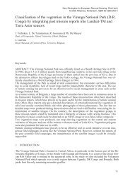
Figure 1. Location <strong>of</strong> <strong>the</strong> test area "<strong>Osterseen</strong> <strong>Lake</strong> <strong>District</strong>" south <strong>of</strong> Munich, Germany.<br />
0 500 m<br />
3.1. Hyperspectral remote sensing data acquired by ROSIS sensor<br />
The Reflective Optics System Imaging Spectroradiometer (ROSIS) was developed since 1986 in cooperation<br />
between DLR, GKSS, and MBB (now Astrium) [5][6][7]. It is a push broom scanner with 512 spatial and 115<br />
spectral pixels recording in <strong>the</strong> wavelength range between 430 nm and 860 nm. The spectral sampling interval<br />
amounts 4 nm and <strong>the</strong> full width at half maximum is about 7.5 nm. With an instantaneous field <strong>of</strong> view <strong>of</strong> 0.59<br />
mrad <strong>the</strong> spatial resolution results in 2.8 x 2.8 m² at a flight altitude <strong>of</strong> 5,000 m.<br />
The data presented in this study were recorded on June 5 th , 2001 between 10:42 and 11:20 UTC in a nor<strong>the</strong>rly flight<br />
direction at an altitude <strong>of</strong> about 5,000 m. The data were radiometrically corrected based on laboratory<br />
measurements using a calibrated light source. The geometric correction <strong>of</strong> <strong>the</strong> distortions due to flight attitude (roll,<br />
pitch, and yaw angles) uses information from <strong>the</strong> airplane's inertial system, <strong>the</strong> flight velocity, <strong>the</strong> altitude above<br />
ground, and <strong>the</strong> focal length <strong>of</strong> <strong>the</strong> telescope [8]. The radiometrically and geometrically corrected composit <strong>of</strong> two<br />
flight lines is shown in Fig. 2.<br />
447