

Rosemount 1153 Series B Alphaline® Nuclear Pressure Transmitter
Rosemount 1153 Series B Alphaline® Nuclear Pressure Transmitter
Rosemount 1153 Series B Alphaline® Nuclear Pressure Transmitter

Create successful ePaper yourself
Turn your PDF publications into a flip-book with our unique Google optimized e-Paper software.
<strong>Rosemount</strong> <strong>1153</strong> <strong>Series</strong> B<br />
5-2<br />
Reference Manual<br />
00809-0100-4302, Rev BA<br />
January 2008<br />
TEST TERMINALS The test terminals are connected across a diode through which the loop<br />
signal current passes. The indicating meter or test equipment shunts the<br />
diode when connected to the test terminals. As long as the voltage across the<br />
terminals is kept below the diode threshold voltage, no current passes<br />
through the diode. To ensure that there is no current leaking through the diode<br />
while making a test reading or when connecting an indicating meter, the<br />
resistance of the test connection or meter should not exceed 10 Ω.<br />
BOARD CHECKOUT NOTE<br />
Numbers in parentheses refer to item numbers in Figure 5-2 on page 5-4.<br />
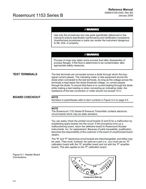
Figure 5-1. Header Board<br />
Connections.<br />
Use only the procedures and new parts specifically referenced in this<br />
manual to ensure specification performance and certification compliance.<br />
Unauthorized procedures or parts can render the instrument dangerous<br />
to life, limb, or property.<br />
Process O-rings may retain some process fluid after disassembly of<br />
process flanges. If this fluid is determined to be contaminated, take<br />
appropriate safety measures.<br />
NOTE<br />
The <strong>Rosemount</strong> <strong>1153</strong> <strong>Series</strong> B <strong>Pressure</strong> <strong>Transmitter</strong> contains electronic<br />
circuit boards which may be static sensitive.<br />
You can easily check the printed circuit boards (5 and 6) for a malfunction by<br />
substituting spare boards into the circuit. If this procedure turns up a<br />
malfunctioning board, return the defective board to <strong>Rosemount</strong> <strong>Nuclear</strong><br />
Instruments, Inc. for replacement. Because of parts traceability, qualification<br />
becomes the responsibility of the customer in the event of unauthorized board<br />
repairs.<br />
The “R” and “P” electronics circuit boards are interchangeable, and either may<br />
be used. They must, however, be used as a pair (i.e., you must use an “R”<br />
calibration board with the “R” amplifier board and not with the “P” amplifier<br />
board). This also applies to the “P” calibration board.<br />
Component Side Up


