Binks Model M1-G HVLP GRAVITY FEED SPRAY GUN - Clemtex
Binks Model M1-G HVLP GRAVITY FEED SPRAY GUN - Clemtex
Binks Model M1-G HVLP GRAVITY FEED SPRAY GUN - Clemtex

Create successful ePaper yourself
Turn your PDF publications into a flip-book with our unique Google optimized e-Paper software.
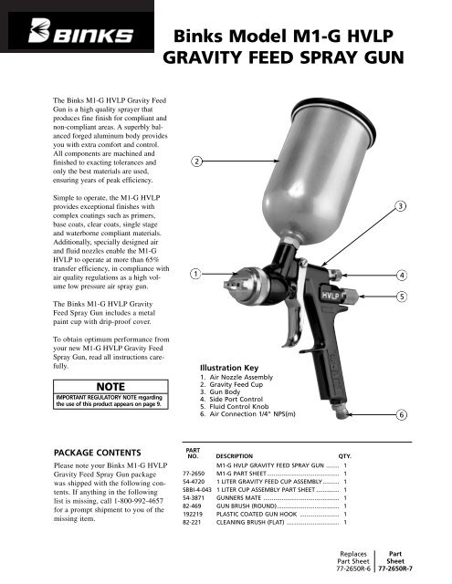
The <strong>Binks</strong> <strong>M1</strong>-G <strong>HVLP</strong> Gravity Feed<br />
Gun is a high quality sprayer that<br />
produces fine finish for compliant and<br />
non-compliant areas. A superbly balanced<br />
forged aluminum body provides<br />
you with extra comfort and control.<br />
All components are machined and<br />
finished to exacting tolerances and<br />
only the best materials are used,<br />
ensuring years of peak efficiency.<br />
Simple to operate, the <strong>M1</strong>-G <strong>HVLP</strong><br />
provides exceptional finishes with<br />
complex coatings such as primers,<br />
base coats, clear coats, single stage<br />
and waterborne compliant materials.<br />
Additionally, specially designed air<br />
and fluid nozzles enable the <strong>M1</strong>-G<br />
<strong>HVLP</strong> to operate at more than 65%<br />
transfer efficiency, in compliance with<br />
air quality regulations as a high volume<br />
low pressure air spray gun.<br />
The <strong>Binks</strong> <strong>M1</strong>-G <strong>HVLP</strong> Gravity<br />
Feed Spray Gun includes a metal<br />
paint cup with drip-proof cover.<br />
To obtain optimum performance from<br />
your new <strong>M1</strong>-G <strong>HVLP</strong> Gravity Feed<br />
Spray Gun, read all instructions carefully.<br />
NOTE<br />
IMPORTANT REGULATORY NOTE regarding<br />
the use of this product appears on page 9.<br />
PACKAGE CONTENTS<br />
Please note your <strong>Binks</strong> <strong>M1</strong>-G <strong>HVLP</strong><br />
Gravity Feed Spray Gun package<br />
was shipped with the following contents.<br />
If anything in the following<br />
list is missing, call 1-800-992-4657<br />
for a prompt shipment to you of the<br />
missing item.<br />
<strong>Binks</strong> <strong>Model</strong> <strong>M1</strong>-G <strong>HVLP</strong><br />
<strong>GRAVITY</strong> <strong>FEED</strong> <strong>SPRAY</strong> <strong>GUN</strong><br />
2<br />
1<br />
Illustration Key<br />
1. Air Nozzle Assembly<br />
2. Gravity Feed Cup<br />
3. Gun Body<br />
4. Side Port Control<br />
5. Fluid Control Knob<br />
6. Air Connection 1/4" NPS(m)<br />
PART<br />
NO. DESCRIPTION QTY.<br />
<strong>M1</strong>-G <strong>HVLP</strong> <strong>GRAVITY</strong> <strong>FEED</strong> <strong>SPRAY</strong> <strong>GUN</strong> ........ 1<br />
77-2650 <strong>M1</strong>-G PART SHEET............................................ 1<br />
54-4720 1 LITER <strong>GRAVITY</strong> <strong>FEED</strong> CUP ASSEMBLY.......... 1<br />
SBBI-4-043 1 LITER CUP ASSEMBLY PART SHEET .............. 1<br />
54-3871 <strong>GUN</strong>NERS MATE .............................................. 1<br />
82-469 <strong>GUN</strong> BRUSH (ROUND)...................................... 1<br />
192219 PLASTIC COATED <strong>GUN</strong> HOOK ........................ 1<br />
82-221 CLEANING BRUSH (FLAT) ................................ 1<br />
Replaces<br />
Part Sheet<br />
77-2650R-6<br />
3<br />
4<br />
5<br />
6<br />
Part<br />
Sheet<br />
77-2650R-7
In this part sheet, the words WARNING, CAUTION and NOTE are used to emphasize important safety information as follows:<br />
2<br />
! ! CAUTION<br />
NOTE<br />
WARNING<br />
Hazards or unsafe practices which could<br />
result in severe personal injury, death or<br />
substantial property damage.<br />
Hazards or unsafe practices which could<br />
result in minor personal injury, product<br />
or property damage.<br />
!<br />
WARNING<br />
Read the following warnings before using this equipment.<br />
READ THE MANUAL<br />
Before operating finishing equipment, read and<br />
understand all safety, operation and maintenance<br />
information provided in the operation manual.<br />
WEAR SAFETY GLASSES<br />
Failure to wear safety glasses with side shields<br />
could result in serious eye injury or blindness.<br />
DE-ENERGIZE, DEPRESSURIZE, DISCONNECT<br />
AND LOCK OUT ALL POWER SOURCES DURING<br />
MAINTENANCE<br />
Failure to De-energize, disconnect and lock out<br />
all power supplies before performing equipment<br />
maintenance could cause serious injury or death.<br />
OPERATOR TRAINING<br />
All personnel must be trained before operating<br />
finishing equipment.<br />
EQUIPMENT MISUSE HAZARD<br />
Equipment misuse can cause the equipment to<br />
rupture, malfunction, or start unexpectedly and<br />
result in serious injury.<br />
KEEP EQUIPMENT GUARDS IN PLACE<br />
Do not operate the equipment if the safety<br />
devices have been removed.<br />
PROJECTILE HAZARD<br />
You may be injured by venting liquids or gases<br />
that are released under pressure, or flying debris.<br />
PINCH POINT HAZARD<br />
Moving parts can crush and cut. Pinch points are<br />
basically any areas where there are moving parts.<br />
AUTOMATIC EQUIPMENT<br />
Automatic equipment may start suddenly without<br />
warning.<br />
INSPECT THE EQUIPMENT DAILY<br />
Inspect the equipment for worn or broken parts<br />
on a daily basis. Do not operate the equipment<br />
if you are uncertain about its condition.<br />
Important installation, operation or<br />
maintenance information.<br />
NEVER MODIFY THE EQUIPMENT<br />
Do not modify the equipment unless the<br />
manufacturer provides written approval.<br />
KNOW WHERE AND HOW TO SHUT OFF THE<br />
EQUIPMENT IN CASE OF AN EMERGENCY<br />
PRESSURE RELIEF PROCEDURE<br />
Always follow the pressure relief procedure in the<br />
equipment instruction manual.<br />
NOISE HAZARD<br />
You may be injured by loud noise. Hearing<br />
protection may be required when using this<br />
equipment.<br />
STATIC CHARGE<br />
Fluid may develop a static charge that must be<br />
dissipated through proper grounding of the<br />
equipment, objects to be sprayed and all other<br />
electrically conductive objects in the dispensing<br />
area. Improper grounding or sparks can cause a<br />
hazardous condition and result in fire, explosion<br />
or electric shock and other serious injury.<br />
FIRE AND EXPLOSION HAZARD<br />
Never use 1,1,1-trichloroethane, methylene<br />
chloride, other halogenated hydrocarbon solvents<br />
or fluids containing such solvents in equipment<br />
with aluminum wetted parts. Such use could<br />
result in a serious chemical reaction, with the<br />
possibility of explosion. Consult your fluid<br />
suppliers to ensure that the fluids being used are<br />
compatible with aluminum parts.<br />
TOXIC FLUID & FUMES<br />
Hazardous fluid or toxic fumes can cause serious<br />
injury or death if splashed in the eyes or on the skin,<br />
inhaled, injected or swallowed. LEARN and KNOW<br />
the specific hazards of the fluids you are using.<br />
WEAR RESPIRATOR<br />
Toxic fumes can cause serious injury or death if<br />
inhaled. Wear a respirator as recommended by<br />
the fluid and solvent manufacturer’s Material<br />
Safety Data Sheet.<br />
FOR FURTHER SAFETY INFORMATION<br />
REGARDING BINKS AND DEVILBISS EQUIPMENT,<br />
SEE THE GENERAL EQUIPMENT SAFETY<br />
BOOKLET (77-5300).
OPERATION and MAINTENANCE INSTRUCTIONS for <strong>M1</strong>-G <strong>HVLP</strong> <strong>SPRAY</strong> <strong>GUN</strong><br />
Your new <strong>M1</strong>-G <strong>HVLP</strong> Spray Gun is exceptionally rugged<br />
in construction and is built to stand up under hard, continuous<br />
use. However, like any other fine precision instrument,<br />
its most efficient operation depends on a knowledge of its<br />
construction, operation and maintenance. Properly handled<br />
and cared for, it will produce beautiful, uniform finishing<br />
results long after other spray guns have worn out.<br />
IMPORTANT: Before removing any components from the<br />
spray gun, shut off air pressure and drain material from the<br />
paint cup.<br />
SETUP FOR <strong>SPRAY</strong>ING<br />
CONNECTING <strong>GUN</strong> TO AIR HOSE<br />
Air should be supplied by a suitable length of 5/16" diameter<br />
air hose fitted with a 1/4 NPS(f) connection at gun end. For<br />
hose lengths over 50', use 3/8" hose.<br />
Air<br />
CONNECTING <strong>GRAVITY</strong> <strong>FEED</strong> CUP TO <strong>GUN</strong><br />
(Figure 1) Screw the cup into the spray gun fluid inlet. Fig. 1<br />
NOTE<br />
All numbers in parentheses ( ) refer to item numbers in<br />
Assembly Drawing on Page 6.<br />
CONTROLLING THE MATERIAL FLOW<br />
Correct fluid nozzle size should be selected for proper<br />
material flow rate. The material valve control knob (19)<br />
may be used to restrict the material needle valve opening<br />
and reduce the material flow as necessary.<br />
FAULTY <strong>SPRAY</strong><br />
A faulty spray is often caused by improper cleaning,<br />
resulting is dried materials around the material nozzle tip<br />
or in the air nozzle. Soak these parts in thinners to soften<br />
the dried material and remove with brush or cloth.<br />
!<br />
CAUTION<br />
Never use metal instruments to clean the air or material<br />
nozzles. These parts are carefully machined and any damage<br />
to them will cause faulty spray.<br />
In certain states, spraying solvents which contain Volatile<br />
Organic Compounds (VOC) into the atmosphere when<br />
cleaning a spray gun is now prohibited.<br />
In order to comply with these new air quality laws <strong>Binks</strong><br />
recommends one of the following two methods to clean<br />
your spray finishing equipment:<br />
1. Spray solvent through the gun into a closed system.<br />
An enclosed unit or spray gun cleaning station condenses<br />
solvent vapors back into liquid form which<br />
prevents escape of VOC’s into the atmosphere.<br />
2. Place spray gun in a washer type cleaner. This<br />
system must totally enclose the spray gun, cups, nozzles<br />
and other parts during washing, rinsing and<br />
draining cycles. This type of unit must be able to<br />
OPERATING THE <strong>M1</strong>-G <strong>HVLP</strong> <strong>SPRAY</strong> <strong>GUN</strong><br />
TROUBLE SHOOTING<br />
<strong>SPRAY</strong> <strong>GUN</strong> CLEANING INSTRUCTIONS<br />
Gravity Feed Cup<br />
Extractor<br />
CONTROLLING THE FAN <strong>SPRAY</strong><br />
The fan spray is controlled by means of the side port<br />
control assembly (9). Turning this control clockwise until<br />
it is closed will give a round spray. Turning it counterclockwise<br />
will widen the spray into a fan shape. The fan<br />
spray can be turned anywhere through 360° by positioning<br />
the air cap (2) relative to the gun. To affect this,<br />
loosen retainer ring, position nozzle, then tighten retainer<br />
ring.<br />
If either the air cap (2) or fluid nozzle (3) are damaged,<br />
these parts must be replaced before perfect spray can be<br />
obtained.<br />
INTERMITTENT <strong>SPRAY</strong><br />
Fluttering spray is caused by either insufficient material<br />
in the gravity feed cup or a clogged fluid passage. If the<br />
fluid passage is clogged, drain material from the paint<br />
cup and remove the cup and fluid nozzle. Clean the fluid<br />
passage with solvent and reassemble.<br />
flush solvent through the gun without releasing any<br />
VOC vapors into the atmosphere.<br />
Additionally, open containers for storage or disposal<br />
of solvent or solvent-containing cloth or paper used for<br />
surface preparation and clean-up may not be used.<br />
Containers shall be nonabsorbent.<br />
CLEANING <strong>GUN</strong> AND <strong>GRAVITY</strong> <strong>FEED</strong> CUP<br />
Remove the cup cover and drain unused material from<br />
cup. Carefully rinse cup with solvent. Place clean solvent<br />
into the cup and spray this through the gun until it is clean.<br />
Remove and clean the cup if necessary. Blow air through<br />
the gun to dry it. (Refer to Service Bulletin SBBI-4-043 for<br />
cleaning instructions when using cup liners.)<br />
3
TO REPLACE AIR VALVE AND SPINDLE ASSEMBLY<br />
Remove material control knob (19), spring (16) and<br />
fluid needle (18). Unscrew housing (17) and remove spindle<br />
assembly (15) with springs (14 & 16), seal<br />
retainers (13) and o-rings (12). Lubricate new o-rings<br />
with Gunner’s Mate. Assemble components using<br />
material needle. Place this assembly along with housing<br />
(17) into gun body and screw into position.<br />
Remove material needle and tighten housing.<br />
MATERIAL<br />
LIGHT: 15 to 20 seconds in a<br />
ZAHN 2 Cup, e.g., stains, varnishes, thin<br />
lacquers, automotive refinishing materials.<br />
MEDIUM: 20 to 60 seconds in a ZAHN 2<br />
Cup, e.g., general industrial coatings<br />
HEAVY: greater than 60 seconds in a<br />
Zahn 2 Cup.<br />
** The 97P or 907P Air Nozzles may be used, but will cause a<br />
significant reduction in fluid flow rate.<br />
Optimum setup for fine automotive spray is 94 x 93P.<br />
✷ ´´BLUE MAX´´ fine finish nozzles. (Retaining ring attached).<br />
• Optional.<br />
▲ Recommended Fluid and Air Nozzle combinations for clear<br />
coat application.<br />
4<br />
MAINTENANCE<br />
FLUID NOZZLES<br />
Standard Fluid Nozzles<br />
FLUID NOZZLE NO.<br />
92 (.046" Dia.) 1.2 mm<br />
92GS (.046" Dia.) 1.2 mm▲<br />
93 (.051" Dia.) 1.3 mm•<br />
94 (.055" Dia.) 1.4 mm<br />
94GS (.055" Dia.) 1.4 mm▲<br />
96GS (.063" Dia.) 1.6 mm▲<br />
97 (.070" Dia.) 1.7 mm<br />
903 (.079" Dia.) 2.0 mm•<br />
905 (.089" Dia.) 2.3 mm<br />
906 (.100" Dia.) 2.5 mm•<br />
909 (.111" Dia.) 2.8 mm•<br />
TO REPLACE CARTRIDGE ASSEMBLY<br />
Remove material valve control knob (19), spring (16) and<br />
remove fluid needle (18). Pull back trigger (21) and<br />
remove seal cartridge assembly (22). Remove and discard<br />
plastic packing pin in new cartridge assembly. Pull back<br />
trigger and insert new seal cartridge assembly. Reassemble<br />
fluid needle (18), spring (16) and material valve control<br />
knob (19).<br />
AIR NOZZLE**<br />
92P•, 93P, 94P•,<br />
95P•, 95AP✷•,<br />
97AP✷•, 90P,<br />
96G▲<br />
905P<br />
NOTE ★<br />
FEATHERING NOZZLES<br />
For applications requiring more gradual Material Valve opening;<br />
metering control of fluid flow is obtained with Gun Trigger.<br />
FLUID NEEDLE<br />
54-4382<br />
54-4547▲<br />
(See Note)★<br />
54-4382<br />
Use stainless steel fluid needle (54-4382) for these nozzles.<br />
Optional nylon-tipped stainless steel fluid needle (54-4381)<br />
is also available. Use 54-4547 needle with 92GS, 94GS and<br />
96GS fluid nozzles.<br />
APPLICABLE FLUID<br />
MATERIAL FLUID NOZZLE NO. AIR NOZZLES** NEEDLE<br />
LIGHT/MEDIUM 94F (.055" Dia.) 1.4 mm• 92P•, 93P■, 94P•,<br />
95P•, 95AP✷•,<br />
97AP✷•<br />
54-4390•<br />
MEDIUM 97F (.070" Dia.) 1.7 mm•<br />
54-4391•<br />
HEAVY 906F (.100" Dia.) 2.5 mm• 905P 54-4394•<br />
909F (.111" Dia.) 2.8 mm• 54-4395•<br />
NOTE<br />
This chart applies to <strong>M1</strong>-G Gravity Feed Guns only.
LVLP AIR NOZZLE 93P<br />
NOZZLE NOZZLE REGULATOR<br />
ATOMIZING ATOMIZING <strong>GUN</strong> INLET PRESSURE<br />
AIR FLOW (SCFM) PRESSURE (PSI) PRESSURE (PSI) (PSI)<br />
5.5 3.0 8.0 10.0<br />
7.0 5.0 11.5 14.0<br />
8.0 7.0 14.5 18.0<br />
9.5 9.0 17.0 22.5<br />
10.0 10.0 18.0 24.0<br />
<strong>HVLP</strong> AIR NOZZLE 96G<br />
NOZZLE NOZZLE REGULATOR<br />
ATOMIZING ATOMIZING <strong>GUN</strong> INLET PRESSURE<br />
AIR FLOW (SCFM) PRESSURE (PSI) PRESSURE (PSI) (PSI)<br />
7.5 3.0 23.0 35.0<br />
14.0 5.0 29.0 42.0<br />
15.5 7.0 33.0 47.0<br />
17.5 9.0 39.0 55.0<br />
19.0 10.0 43.0 60.0<br />
LVLP AIR NOZZLES 92P<br />
NOZZLE NOZZLE REGULATOR<br />
ATOMIZING ATOMIZING <strong>GUN</strong> INLET PRESSURE<br />
AIR FLOW (SCFM) PRESSURE (PSI) PRESSURE (PSI) (PSI)<br />
4.5 3.0 6.0 9.0<br />
6.0 5.0 8.5 10.0<br />
6.8 7.0 11.5 14.0<br />
7.5 9.0 13.5 18.0<br />
8.0 10.0 15.0 19.0<br />
92P and 93P are for general industrial and automotive finish applications.<br />
<strong>HVLP</strong> AIR NOZZLES 95P, 97P, 95AP, 97AP, 905P, 907P<br />
NOZZLE NOZZLE REGULATOR<br />
ATOMIZING ATOMIZING <strong>GUN</strong> INLET PRESSURE<br />
AIR FLOW (SCFM) PRESSURE (PSI) PRESSURE (PSI) (PSI)<br />
11.0 3.0 20.0 27.0<br />
15.7 5.0 30.0 40.0<br />
17.5 7.0 38.0 50.0<br />
19.6 9.0 45.0 58.0<br />
22.5 10.0 50.0 64.0<br />
<strong>HVLP</strong> AIR NOZZLE 94P<br />
NOZZLE NOZZLE <strong>GUN</strong> INLET<br />
AIR FLOW ATOMIZING PRESSURE<br />
(SCFM) (PSI) (PSI)<br />
7.0 3.0 14.0<br />
9.0 5.0 21.0<br />
11.0 7.0 27.0<br />
12.0 9.0 30.0<br />
13.0 10.0 33.0<br />
AIR NOZZLES<br />
AIR PRESSURE RECOMMENDATIONS<br />
TYPE OF MATERIAL<br />
ATOMIZING<br />
PSI<br />
Light Stains, Inks 3-4<br />
Primer/surfaces 5-6<br />
Acrylic Enamels 7-8<br />
Lacquers 7-8<br />
Low VOC, Urethanes 8-10<br />
AIR NOZZLE RECOMMENDATIONS:<br />
The 93P and 905P Air Nozzles are most suitable<br />
for conventional materials. Use of very low fluid<br />
delivery rates with these Nozzles will produce a<br />
narrower than normal fan pattern.<br />
Use the 97P and 907P Air Nozzles for heavy bodied,<br />
high solids materials and low fluid flow rates<br />
with conventional materials. High flow rates<br />
with light bodied materials may result in some<br />
minor “smoking” or material build-up on the<br />
face of these nozzles.<br />
USE OF THE 95AS OR 97AS SIPHON NOZZLES IS<br />
NOT RECOMMENDED WITH THE <strong>M1</strong>-G <strong>GRAVITY</strong><br />
<strong>FEED</strong> <strong>GUN</strong>.<br />
NOTE<br />
Regulator pressures are based on 25' of 5/16"<br />
Hose in good condition without Quick-<br />
Disconnects or other restrictive fittings. Use<br />
the Air Nozzle Test Gauge accessory to confirm<br />
the atomizing/regulator pressure relationship<br />
for your actual air supply set-up. These<br />
recommendations are for “typical” or<br />
“average” materials, and are intended to<br />
serve as a starting point. Adjust as necessary<br />
for your specific application.<br />
5
ASSEMBLY DRAWING FOR THE <strong>M1</strong>-G <strong>GRAVITY</strong> <strong>FEED</strong> <strong>SPRAY</strong> <strong>GUN</strong><br />
6<br />
31<br />
25<br />
27<br />
28<br />
32<br />
REFER TO SERVICE<br />
BULLETIN SBBI-4-043 FOR:<br />
9<br />
• Warnings and cautions for<br />
cup assembly 54-4720.<br />
30<br />
11<br />
• Assembly instructions for<br />
the liner (not shown).<br />
10<br />
• Cleaning instructions for the<br />
cup assembly when used<br />
with or without the liner. 24<br />
6<br />
15<br />
7<br />
14<br />
17<br />
13<br />
12<br />
12<br />
13<br />
5<br />
16<br />
4<br />
8<br />
3<br />
18<br />
23<br />
2<br />
29<br />
19<br />
22<br />
21<br />
26<br />
16<br />
20<br />
1
PARTS LIST<br />
(When ordering, please specify PART NO.)<br />
ITEM PART<br />
NO. NO. DESCRIPTION QTY.<br />
1 54-3531 RETAINING RING ........................................................ 1<br />
2 ★ AIR CAP ...................................................................... 1<br />
3 ★ FLUID NOZZLE ............................................................ 1<br />
4 54-4368 HEAD INSERT .............................................................. 1<br />
5 54-4369-5▲❍ HEAD INSERT SEAL RING .......................................... 1<br />
6 54-4361▼ <strong>M1</strong>-G HANDLE ASSEMBLY<br />
7 54-4359 TRIGGER STUD............................................................ 1<br />
8 82-126 TRIGGER SCREW ........................................................ 1<br />
9 54-4364● SIDE PORT CONTROL ASSEMBLY .............................. 1<br />
10 54-3511▲ RETAINING RING ........................................................ 1<br />
11 20-6160▲ O-RING ........................................................................ 1<br />
12 20-4615-5▲❍ O-RING ........................................................................ 2<br />
13 54-3515 SEAL RETAINER .......................................................... 2<br />
14 54-3520▲ SPRING (Yellow) .......................................................... 1<br />
15 54-3512▲ SPINDLE ASSEMBLY .................................................... 1<br />
16 54-3518▲ SPRING (Blue) .............................................................. 2<br />
17 54-3541 HOUSING .................................................................... 1<br />
18 ★ FLUID NEEDLE ............................................................ 1<br />
19 54-3606 MATERIAL VALVE CONTROL KNOB .......................... 1<br />
20 54-768 AIR CONNECTION<br />
21 54-4360 TRIGGER...................................................................... 1<br />
22 54-4370▲ SEAL CARTRIDGE ASSEMBLY .................................... 1<br />
23 54-3513 VALVE SPINDLE CAP .................................................. 1<br />
24 54-4720 1 LITER <strong>GRAVITY</strong> <strong>FEED</strong> CUP ASSEMBLY .................... 1<br />
25 GFC-404❏ DISPOSABLE LID ASSEMBLY<br />
(Quantity 2 supplied / 54-4720)<br />
26 KGP-13▲✚ CUP GASKET (Blue)...................................................... 1<br />
27 54-3918 WRENCH (Optional) .................................................... 1<br />
28 82-469 <strong>GUN</strong> BRUSH (Round) .................................................. 1<br />
29 KGP-5✹ FILTER ..........................................................................<br />
30 192219 PLASTIC COATED <strong>GUN</strong> HOOK.................................... 1<br />
31 54-3871◆ <strong>GUN</strong>NER’S MATE ........................................................ 1<br />
32 82-221 CLEANING BRUSH (Flat) .............................................. 1<br />
33 OMX-70 ✖ DISPOSABLE LINER (Not Shown)<br />
(Refer to Service Bulletin SBBI-4-043)<br />
★ See Air and Fluid Nozzle Chart on Page 4.<br />
● Optional: Side Port Control Assembly 54-4365 (QCSP).<br />
✹ Available in 54-4716 Filter Kit (quantity of 5) only.<br />
▲ Available in Spare Parts Kit 54-4367.<br />
Not furnished. Please order separately.<br />
▼ Item NOT available separately.<br />
◆ Available from Industrial Finishing distributors only.<br />
❍ Available only as a Quantity Pak.<br />
❏ Available in 54-4715 Disposable Lid Kit (quantity of 2) only.<br />
✚ Available in 54-4717 Cup Gasket (Blue) Kit (quantity of 5) only.<br />
✖ Available in OMX-70-K48 Disposable Liner Kit (quantity of 48) only.<br />
7
To reduce overspray and obtain maximum efficiency,<br />
always spray with the lowest possible fluid/air pressure<br />
that produces an acceptable spray pattern.<br />
Excessive atomizing air pressures can increase overspray,<br />
reduce transfer efficiency, and with some materials, result<br />
in poor finish quality from dry spray. Atomizing air pres-<br />
The first requirement for a good resultant finish is the<br />
proper handling of the gun. The gun should be held perpendicular<br />
to the surface being covered and moved parallel<br />
with it. The stroke should be started before the trigger<br />
is pulled, and the trigger should be released before the<br />
stroke is ended. This gives accurate control of the gun<br />
and material.<br />
Approx.<br />
5 1/2 psi<br />
at Nozzle<br />
8<br />
1/4"<br />
6 to 12 inches<br />
NOT RECOMMENDED<br />
GENERAL <strong>SPRAY</strong> INSTRUCTIONS<br />
<strong>SPRAY</strong> TECHNIQUE<br />
Coating should be even<br />
and wet when spraying<br />
sures should not exceed 10 psi. See table on page 5, diagram<br />
on this page and Regulatory Note on page 9.<br />
Generally use 30 - 35 psi at gun inlet (see below).<br />
Unusually heavy, difficult to atomize materials may<br />
require up to 50 psi air at gun head.<br />
The distance between gun and surface should be 6 to 10<br />
inches depending on material and atomizing pressure.<br />
The material deposited should always be even and wet.<br />
Lap each stroke over the preceding stroke to obtain a uniform<br />
finish.<br />
Oil and Water Extractor is important<br />
Achieving a fine spray finish without the use of a good oil and water extractor is<br />
virtually impossible.<br />
A Regulator/Extractor serves a double purpose. It eliminates blistering and spotting<br />
by keeping air free of oil and water and it gives precise air pressure control at the<br />
gun. See page 3 regarding installation of extractors.<br />
Atomizing pressure must be set to allow for the drop in air pressure between the<br />
regulator and the spray gun.<br />
HOSE RECOMMENDATION<br />
With 60 psi applied at air supply:<br />
Only 34 psi<br />
at Gun Inlet<br />
25 feet of<br />
1/4" I.D. hose<br />
causes a drop<br />
of 26 psi<br />
between the<br />
air supply<br />
and the gun.<br />
Approx.<br />
9 psi<br />
at Nozzle<br />
Cross section view showing comparison of<br />
inside hose diameters (actual size). 60 lbs<br />
regulated pressure.<br />
RECOMMENDED<br />
48 psi<br />
at Gun Inlet<br />
25 feet of 5/16" I.D.<br />
hose causes a drop<br />
of 12 psi between<br />
the air supply and<br />
the gun. For this<br />
reason we recommend<br />
the use of 5/16" hose.<br />
5/16"
IMPORTANT REGULATORY NOTE<br />
Some Regulatory Agencies prohibit the operation of <strong>HVLP</strong> spray guns above 10 psi nozzle atomizing<br />
pressure. Users subject to this type of regulation should not exceed the gun inlet pressure indicated on<br />
the air cap. See General Spray Instructions and Air Pressure Recommendations, page 8. It is recommended<br />
that the nozzle test gauge (see below) be used to confirm actual nozzle operating pressure.<br />
It may also be a requirement of some regulatory agencies that users have this gauge nozzle available on<br />
site to verify that the gun is being operated within the limits of applicable rules.<br />
AIR NOZZLE TEST GAUGE ASSEMBLY<br />
54-3935 for 95P, 97P, 95AP, and 97AP Nozzles.<br />
54-3908◆ for 900 Series Nozzles.<br />
54-4345◆ for 90P Air Nozzle.<br />
54-4356 for 93P Air Nozzle.<br />
54-3902◆ for 92P Air Nozzle.<br />
54-4066◆ for 94P Air Nozzle.<br />
54-4566 for 96G Air Nozzle.<br />
◆Available from Industrial<br />
Distributors only.<br />
54-4350<br />
Gun Stand<br />
(Optional)<br />
59-299<br />
Gauge◆<br />
54-4352<br />
Gun Bracket<br />
(Optional)<br />
ACCESSORIES<br />
(When ordering, please specify PART NO.)<br />
Part No. Description<br />
54-4350 Gun Stand<br />
54-4352 Gun Bracket<br />
192219 Plastic Coated Gun Hook<br />
81-82 Strainer<br />
145 Mesh—typical for Lacquers<br />
81-83 Strainer<br />
100 Mesh—typical for Metal Flake<br />
81-84 Strainer<br />
80 Mesh—typical for Primers<br />
192219<br />
Plastic Coated Gun Hook<br />
(Supplied with outfit)<br />
9
10<br />
NOTES
NOTES<br />
11
WARRANTY<br />
This product is covered by <strong>Binks</strong>’ 1 Year Limited Warranty.<br />
<strong>Binks</strong> Worldwide Sales and Service Listing: www.binks.com<br />
ITW Industrial Finishing<br />
<strong>Binks</strong> has authorized distributors throughout the world. For technical<br />
assistance or the distributor nearest you, see listing below.<br />
U.S./Canada Technical Service Office:<br />
195 Internationale Blvd., Glendale Heights, IL 60139<br />
Toll-Free Telephone: 1-888-992-4657 (U.S.A. and Canada only)<br />
Toll-Free Fax: 1-888-246-5732<br />
77-2650R-7 Revisions: (P1) Deleted reference air nozzle availability; (P4) Added<br />
Fluid Needle 54-4382 reference to chart.<br />
9/07 © 2007 Illinois Tool Works Inc. All rights reserved. Printed in U.S.A.