Cavitation and Hydraulic Flip in the Outward-Opening GDi ... - Delphi
Cavitation and Hydraulic Flip in the Outward-Opening GDi ... - Delphi
Cavitation and Hydraulic Flip in the Outward-Opening GDi ... - Delphi
You also want an ePaper? Increase the reach of your titles
YUMPU automatically turns print PDFs into web optimized ePapers that Google loves.
Copyright © 2009 SAE International<br />
ABSTRACT<br />
Experimental (optical imag<strong>in</strong>g) <strong>and</strong> CFD <strong>in</strong>vestigations of<br />
<strong>the</strong> cavitat<strong>in</strong>g flow <strong>in</strong> a transparent large-scale model of a<br />
<strong>GDi</strong> outward-open<strong>in</strong>g <strong>in</strong>jector, with a swirler-type valvegroup,<br />
has been performed. The objective is to elucidate<br />
<strong>the</strong> flow structure with<strong>in</strong> <strong>the</strong> valve group <strong>and</strong> assess a<br />
Reynolds-Averaged Navier-Stokes (RANS) multi-fluid<br />
simulation method.<br />
The optical imag<strong>in</strong>g data show evidence of cavitation<br />
<strong>in</strong>ception <strong>in</strong> <strong>the</strong> valve-group swirler-channels - caused by<br />
<strong>the</strong> rapid flow acceleration - <strong>and</strong> multiple cavitations<br />
with<strong>in</strong> <strong>the</strong> conical nozzle region.<br />
The comparison of simulations with data shows that <strong>the</strong><br />
CFD method reproduces <strong>the</strong> fluid dynamics of <strong>the</strong> valvegroup<br />
with good qualitative agreement with <strong>the</strong> imag<strong>in</strong>g<br />
data (with respect to <strong>the</strong> cavitation <strong>in</strong>ception <strong>and</strong><br />
geometry) <strong>and</strong> excellent quantitative agreement of <strong>the</strong><br />
valve-group pressure drop - flow rate characteristic. In<br />
addition, <strong>the</strong> simulations reveal that <strong>the</strong> apparent<br />
cavitation <strong>in</strong> <strong>the</strong> conical nozzle region <strong>in</strong>volves a “partial<br />
hydraulic flip” phenomena <strong>and</strong> entra<strong>in</strong>ment of <strong>the</strong><br />
ambient air.<br />
INTRODUCTION<br />
The gasol<strong>in</strong>e direct-<strong>in</strong>jection (<strong>GDi</strong>) spray-guided<br />
combustion technology has been adopted by <strong>the</strong><br />
European automotive <strong>in</strong>dustry as <strong>the</strong> primary gasol<strong>in</strong>e<br />
eng<strong>in</strong>e technology progression to meet <strong>the</strong> economical<br />
<strong>and</strong> legislative pressures for reduction of <strong>the</strong> automotive<br />
fuel consumption <strong>and</strong> combustion emissions[1,2]. It<br />
The Eng<strong>in</strong>eer<strong>in</strong>g Meet<strong>in</strong>gs Board has approved this paper for publication. It has successfully completed SAE’s peer review process under <strong>the</strong> supervision of<br />
<strong>the</strong> session organizer. This process requires a m<strong>in</strong>imum of three (3) reviews by <strong>in</strong>dustry experts.<br />
All rights reserved. No part of this publication may be reproduced, stored <strong>in</strong> a retrieval system, or transmitted, <strong>in</strong> any form or by any means, electronic,<br />
mechanical, photocopy<strong>in</strong>g, record<strong>in</strong>g, or o<strong>the</strong>rwise, without <strong>the</strong> prior written permission of SAE.<br />
ISSN 0148-7191<br />
Positions <strong>and</strong> op<strong>in</strong>ions advanced <strong>in</strong> this paper are those of <strong>the</strong> author(s) <strong>and</strong> not necessarily those of SAE. The author is solely responsible for <strong>the</strong> content of<br />
<strong>the</strong> paper.<br />
SAE Customer Service: Tel: 877-606-7323 (<strong>in</strong>side USA <strong>and</strong> Canada)<br />
Tel: 724-776-4970 (outside USA)<br />
Fax: 724-776-0790<br />
Email: CustomerService@sae.org<br />
SAE Web Address: http://www.sae.org<br />
*9-2009-01-1483*<br />
Pr<strong>in</strong>ted <strong>in</strong> USA<br />
2009-01-1483<br />
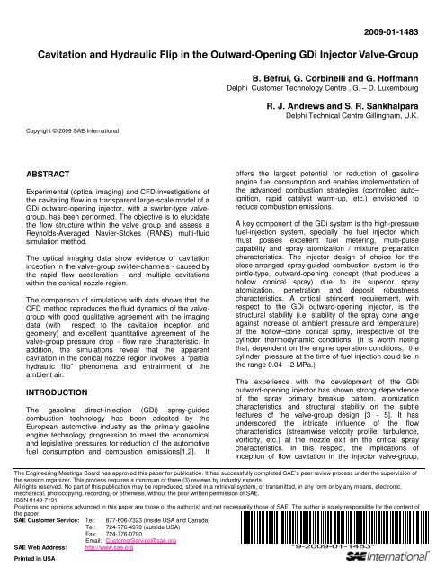
<strong>Cavitation</strong> <strong>and</strong> <strong>Hydraulic</strong> <strong>Flip</strong> <strong>in</strong> <strong>the</strong> <strong>Outward</strong>-Open<strong>in</strong>g <strong>GDi</strong> Injector Valve-Group<br />
B. Befrui, G. Corb<strong>in</strong>elli <strong>and</strong> G. Hoffmann<br />
<strong>Delphi</strong> Customer Technology Centre , G. – D. Luxembourg<br />
R. J. Andrews <strong>and</strong> S. R. Sankhalpara<br />
<strong>Delphi</strong> Technical Centre Gill<strong>in</strong>gham, U.K.<br />
offers <strong>the</strong> largest potential for reduction of gasol<strong>in</strong>e<br />
eng<strong>in</strong>e fuel consumption <strong>and</strong> enables implementation of<br />
<strong>the</strong> advanced combustion strategies (controlled auto–<br />
ignition, rapid catalyst warm-up, etc.) envisioned to<br />
reduce combustion emissions.<br />
A key component of <strong>the</strong> <strong>GDi</strong> system is <strong>the</strong> high-pressure<br />
fuel-<strong>in</strong>jection system, specially <strong>the</strong> fuel <strong>in</strong>jector which<br />
must posses excellent fuel meter<strong>in</strong>g, multi-pulse<br />
capability <strong>and</strong> spray atomization / mixture preparation<br />
characteristics. The <strong>in</strong>jector design of choice for <strong>the</strong><br />
close-arranged spray-guided combustion system is <strong>the</strong><br />
p<strong>in</strong>tle-type, outward-open<strong>in</strong>g concept (that produces a<br />
hollow conical spray) due to its superior spray<br />
atomization, penetration <strong>and</strong> deposit robustness<br />
characteristics. A critical str<strong>in</strong>gent requirement, with<br />
respect to <strong>the</strong> <strong>GDi</strong> outward-open<strong>in</strong>g <strong>in</strong>jector, is <strong>the</strong><br />
structural stability (i.e. stability of <strong>the</strong> spray cone angle<br />
aga<strong>in</strong>st <strong>in</strong>crease of ambient pressure <strong>and</strong> temperature)<br />
of <strong>the</strong> hollow–cone conical spray, irrespective of <strong>the</strong><br />
cyl<strong>in</strong>der <strong>the</strong>rmodynamic conditions. (It is worth not<strong>in</strong>g<br />
that, dependent on <strong>the</strong> eng<strong>in</strong>e operation conditions, <strong>the</strong><br />
cyl<strong>in</strong>der pressure at <strong>the</strong> time of fuel <strong>in</strong>jection could be <strong>in</strong><br />
<strong>the</strong> range 0.04 – 2 MPa.)<br />
The experience with <strong>the</strong> development of <strong>the</strong> <strong>GDi</strong><br />
outward-open<strong>in</strong>g <strong>in</strong>jector has shown strong dependence<br />
of <strong>the</strong> spray primary breakup pattern, atomization<br />
characteristics <strong>and</strong> structural stability on <strong>the</strong> subtle<br />
features of <strong>the</strong> valve-group design [3 - 5]. It has<br />
underscored <strong>the</strong> <strong>in</strong>tricate <strong>in</strong>fluence of <strong>the</strong> flow<br />
characteristics (streamwise velocity profile, turbulence,<br />
vorticity, etc.) at <strong>the</strong> nozzle exit on <strong>the</strong> critical spray<br />
characteristics. In this respect, <strong>the</strong> implications of<br />
<strong>in</strong>ception of flow cavitation <strong>in</strong> <strong>the</strong> <strong>in</strong>jector valve-group,
caused by <strong>in</strong>evitable variations of <strong>the</strong> fuel temperature<br />
<strong>and</strong>/or composition, that could simultaneously affect <strong>the</strong><br />
static flow rate <strong>and</strong> engender major alterations of <strong>the</strong><br />
nozzle exit velocity characteristics, are of serious<br />
concern.<br />
There is a need for development of a fundamental<br />
knowledge of <strong>the</strong> high-pressure, hollow-cone sprays of<br />
<strong>the</strong> <strong>GDi</strong> <strong>in</strong>jectors, with respect to <strong>the</strong> spray atomization<br />
characteristics <strong>and</strong> its dependence on <strong>the</strong> valve-group<br />
design <strong>and</strong> <strong>the</strong> fuel system operation parameters. An<br />
<strong>in</strong>tegral element of this activity is <strong>the</strong> development,<br />
validation <strong>and</strong> application of computational methods to<br />
assist analyses of <strong>the</strong> relationship between <strong>the</strong> fluid<br />
dynamics of <strong>the</strong> <strong>in</strong>jector valve-group <strong>and</strong> <strong>the</strong> associated<br />
spray atomization characteristics. Therefore, jo<strong>in</strong>t optical<br />
/ laser diagnostics experimental <strong>and</strong> advanced<br />
computational activities have been undertaken at <strong>the</strong><br />
<strong>Delphi</strong> Customer Technology Center Luxembourg to<br />
address <strong>the</strong> dual objectives for development/validation of<br />
experimental/analytical methods <strong>and</strong> establishment of a<br />
broad knowledge of <strong>the</strong> <strong>GDi</strong> hollow-cone spray<br />
atomization characteristics necessary to meet <strong>the</strong><br />
customer-specific requirements for a robust <strong>and</strong> stable<br />
spray formation [5 , 6].<br />
The present study is concerned with experimental <strong>and</strong><br />
computational <strong>in</strong>vestigation of <strong>the</strong> flow <strong>in</strong> a large-scale<br />
model of a <strong>GDi</strong> outward-open<strong>in</strong>g valve-group that<br />
<strong>in</strong>corporates a swirler component upstream of <strong>the</strong><br />
conical nozzle. The <strong>in</strong>corporation of <strong>the</strong> swiler serves two<br />
purposes: it enables accurate static-flow sett<strong>in</strong>g (<strong>and</strong><br />
reduces <strong>the</strong> fuel meter<strong>in</strong>g sensitivity to variations of p<strong>in</strong>tle<br />
stroke) <strong>and</strong> imports tangential momentum onto <strong>the</strong> flow,<br />
<strong>the</strong>reby improv<strong>in</strong>g <strong>the</strong> spray penetration <strong>and</strong> atomization<br />
characteristics. However, it poses concerns with respect<br />
to possible cavitation <strong>in</strong>ception, with<strong>in</strong> <strong>the</strong> swirler<br />
passages <strong>and</strong> <strong>the</strong> conical nozzle, <strong>and</strong> <strong>the</strong> consequent<br />
<strong>in</strong>fluences on <strong>the</strong> spray structure. These could engender<br />
circumferential non-uniformity of <strong>the</strong> liquid sheet<br />
thickness <strong>and</strong> nozzle-exit velocity, with notable effects on<br />
<strong>the</strong> spray primary breakup <strong>and</strong> atomization<br />
characteristics. A second topic of <strong>in</strong>terest is whe<strong>the</strong>r a<br />
transition of cavitation to full/partial hydraulic flip will<br />
occur with<strong>in</strong> <strong>the</strong> conical nozzle, for <strong>the</strong> fuel pressure<br />
ratios comparable to <strong>the</strong> <strong>GDi</strong> fuel system nom<strong>in</strong>al levels.<br />
The cavitation phenomena <strong>in</strong> <strong>the</strong> fuel <strong>in</strong>jection nozzles<br />
<strong>and</strong> its effect on <strong>the</strong> spray atomization characteristics<br />
has been <strong>in</strong>vestigated for <strong>the</strong> cyl<strong>in</strong>drical nozzles - as <strong>the</strong><br />
most common <strong>in</strong>dustrial <strong>in</strong>jector nozzle geometry - <strong>in</strong><br />
relation to <strong>the</strong> full-cone sprays of diesel <strong>in</strong>jectors [7 - 11]<br />
<strong>and</strong> o<strong>the</strong>r <strong>in</strong>dustrial fields of application [12]. In general a<br />
direct correlation between cavitation <strong>in</strong>ception <strong>in</strong> <strong>the</strong><br />
nozzle-hole <strong>and</strong> enhancement of <strong>the</strong> liquid-jet<br />
atomization has been observed. More recently, <strong>the</strong><br />
transformation of cavitation to hydraulic flip has become<br />
<strong>the</strong> focus of attention, due to its caus<strong>in</strong>g <strong>the</strong> irregular<br />
“flipp<strong>in</strong>g” of <strong>the</strong> spray trajectory [13].<br />
The hydraulic flip phenomena is closely – <strong>and</strong><br />
predom<strong>in</strong>antly - associated with <strong>the</strong> cavitation <strong>in</strong> <strong>the</strong><br />
nozzle of high-pressure full-cone liquid jets. It is referred<br />
to as <strong>the</strong> condition whereby <strong>the</strong> cavitation bubble<br />
exceeds <strong>the</strong> “super-critical cavitation” condition , extends<br />
beyond <strong>the</strong> nozzle doma<strong>in</strong> <strong>and</strong> merges with <strong>the</strong> ambient.<br />
Consequently, <strong>the</strong> ambient air (which normally is at<br />
higher pressure than <strong>the</strong> vapour saturation pressure) is<br />
drawn <strong>in</strong>to <strong>the</strong> cavitation doma<strong>in</strong> <strong>and</strong> forms a “cushion”<br />
between <strong>the</strong> liquid core <strong>and</strong> <strong>the</strong> nozzle walls. This has<br />
remarkable <strong>in</strong>fluence on <strong>the</strong> structure <strong>and</strong> breakup of <strong>the</strong><br />
issu<strong>in</strong>g liquid jet, through (a) <strong>in</strong>hibition of <strong>the</strong> liquid-phase<br />
near-wall turbulence production <strong>and</strong> (b) enhancement of<br />
<strong>the</strong> liquid-air <strong>in</strong>terface <strong>in</strong>stability dynamics. Also,<br />
dependent on <strong>the</strong> nozzle geometry <strong>and</strong> entrance flow<br />
irregularity, <strong>the</strong>re is high probability of asymmetric or<br />
partial hydraulic flips which engender sudden change of<br />
<strong>the</strong> spray geometry <strong>and</strong> trajectory [13].<br />
The experimental <strong>in</strong>vestigations of <strong>the</strong> flow <strong>in</strong> <strong>the</strong> largescale<br />
models of <strong>the</strong> <strong>GDi</strong> outward-open<strong>in</strong>g <strong>in</strong>jector show<br />
evidence of presence of a gaseous-phase with<strong>in</strong> <strong>the</strong><br />
nozzle doma<strong>in</strong> (i.e. upstream of <strong>the</strong> nozzle exit) which is<br />
often <strong>in</strong>terpreted as flow cavitation. However, recent CFD<br />
Large-Eddy Simulations (LES) have revealed occurrence<br />
of “<strong>in</strong>gestion” (or entra<strong>in</strong>ment) of ambient air <strong>in</strong>to <strong>the</strong><br />
<strong>in</strong>jector nozzle doma<strong>in</strong>, with substantial <strong>in</strong>fluence on <strong>the</strong><br />
nozzle-exit structure of <strong>the</strong> conical-sheet liquid-jet <strong>and</strong><br />
its near-field breakup pattern [5]. In <strong>the</strong> context of <strong>the</strong><br />
present study, partial hydraulic flip is adopted broadly for<br />
an entra<strong>in</strong>ment of <strong>the</strong> ambient air <strong>in</strong>to <strong>the</strong> nozzle doma<strong>in</strong>,<br />
that causes formation of an “air-cushion” that separates<br />
<strong>the</strong> liquid flow from <strong>the</strong> conical nozzle walls.<br />
The large-scale experimental <strong>in</strong>vestigation is<br />
complemented by <strong>the</strong> CFD multi-fluid Reynoldsaveraged<br />
Navier-Stokes simulations of <strong>the</strong> two- <strong>and</strong><br />
three-fluid flow with<strong>in</strong> <strong>the</strong> <strong>in</strong>jector valve group <strong>and</strong> its<br />
neighbor<strong>in</strong>g downstream ambient. The objective is to<br />
<strong>in</strong>vestigate <strong>the</strong> capability, <strong>the</strong> qualitative <strong>and</strong> <strong>the</strong><br />
quantitative accuracy of current CFD method – as<br />
available <strong>in</strong> commercial CFD codes - for prediction of <strong>the</strong><br />
cavitation <strong>in</strong>ception, <strong>the</strong> cavitation geometry <strong>and</strong> <strong>the</strong><br />
cavitation effect on <strong>the</strong> valve-group hydrodynamic<br />
parameters. For this purpose, specifically a valve group<br />
design with experimental evidence of multiple cavitation<br />
regions has been selected, because of <strong>the</strong> specific<br />
<strong>in</strong>terest to assess <strong>the</strong> capability to accurately predict<br />
dist<strong>in</strong>ct, multiple cavitation regions with<strong>in</strong> <strong>the</strong> simulation<br />
doma<strong>in</strong> (<strong>in</strong> particular to verify that <strong>in</strong>ception of cavitation<br />
at a flow upstream location does not affect <strong>the</strong> prediction<br />
of its <strong>in</strong>ception <strong>and</strong> geometric features at a downstream<br />
location).<br />
EXPERIMENTAL INVESTIGATIONS<br />
The large scale model of a gasol<strong>in</strong>e direct <strong>in</strong>jection (<strong>GDi</strong>)<br />
<strong>in</strong>jector’s outward-open<strong>in</strong>g valve-group – with alternative<br />
swirler geometries - is constructed <strong>and</strong> tested <strong>in</strong> <strong>the</strong><br />
Physical Modell<strong>in</strong>g Group at <strong>the</strong> <strong>Delphi</strong> Technical Centre
<strong>in</strong> Gill<strong>in</strong>gham. The experimental methodologies applied<br />
are photographic imag<strong>in</strong>g, <strong>in</strong> conjunction with<br />
measurements of <strong>the</strong> pressure <strong>and</strong> flow rate. The focus<br />
of <strong>the</strong> study is to obta<strong>in</strong> basic flow <strong>in</strong>formation regard<strong>in</strong>g<br />
<strong>the</strong> condition of flow with<strong>in</strong> <strong>the</strong> <strong>in</strong>jector – with <strong>the</strong> aid of<br />
imag<strong>in</strong>g <strong>and</strong> pressure measurement at several locations<br />
- <strong>and</strong> <strong>the</strong> spray. This <strong>in</strong>formation is <strong>in</strong>tended to assist<br />
development of <strong>the</strong> valve-group design <strong>and</strong> support<br />
validation of a current state-of-<strong>the</strong>-art CFD multi-phase<br />
simulation method.<br />
The large-scale modell<strong>in</strong>g uses <strong>the</strong> pr<strong>in</strong>ciples of<br />
geometric <strong>and</strong> dynamic similarity for steady state flow<br />
conditions. In this respect, <strong>the</strong> two most relevant nondimensional<br />
groups are <strong>the</strong> Reynolds number <strong>and</strong><br />
cavitation number, to match <strong>the</strong> model operation<br />
condition with that of <strong>the</strong> actual-size counterpart. The<br />
Reynolds number similarity takes account of <strong>the</strong> different<br />
properties of <strong>the</strong> actual-size fluid (i.e. n-Heptane) <strong>and</strong> <strong>the</strong><br />
large-scale work<strong>in</strong>g fluid (i.e. ISO4113 calibration fluid).<br />
Table 1 presents <strong>the</strong> correspondence between <strong>the</strong> largescale<br />
model tests <strong>and</strong> <strong>the</strong> actual-size <strong>in</strong>jector operation.<br />
Actual size Model (x35)<br />
Liquid Properties<br />
Work<strong>in</strong>g Fluid n - Heptane<br />
ISO 4113<br />
calibration<br />
fluid<br />
Viscosity [mm2/s] 0.575 2.75<br />
Density [kg/m3] 680 817<br />
Vapour Pressure [bar] 0.0413 0.002<br />
System Pressure [MPa]<br />
5 0.112<br />
10 0.224<br />
15 0.337<br />
20 0.449<br />
Ambient Pressure [MPa]<br />
0.4 0.009<br />
Table 1. Correspondence of <strong>the</strong> Large-scale model<br />
tests <strong>and</strong> actual-size <strong>in</strong>jector operation<br />
EXPERIMENTAL FLOW RIG - Figure 1 shows <strong>the</strong> flow<br />
rig <strong>and</strong> <strong>the</strong> large-scale model <strong>in</strong> situ. The static<br />
pressures at <strong>the</strong> tapp<strong>in</strong>gs are measured with a<br />
Scanivalve unit us<strong>in</strong>g a calibrated transducer, <strong>and</strong><br />
processed / stored via a personal computer. The flow<br />
rate is cont<strong>in</strong>uously monitored with a vane-type flow<br />
meter. In order to create <strong>the</strong> correct flow cavitation<br />
number, <strong>the</strong> <strong>GDi</strong> valve -group model discharges <strong>in</strong>to a<br />
vacuum chamber.<br />
LARGE-SCALE VALVE-GROUP MODEL - The model is<br />
shown <strong>in</strong> Figure 2. It is modular <strong>in</strong> construction to allow<br />
design changes to be easily implemented. The ma<strong>in</strong><br />
hous<strong>in</strong>g <strong>and</strong> <strong>the</strong> swirler are manufactured from acrylic<br />
material to allow view<strong>in</strong>g of <strong>the</strong> cavitations regions <strong>in</strong> <strong>the</strong><br />
fluid flow. The p<strong>in</strong>tle can be adjusted to be concentric or<br />
eccentric <strong>in</strong> <strong>the</strong> guide bore. A leakage path orifice is<br />
fitted <strong>in</strong>to <strong>the</strong> swirler plate to model leakage flow through<br />
<strong>the</strong> p<strong>in</strong>tle - guide clearance annulus.<br />
Figure 1. The <strong>in</strong>-situ assembled model <strong>and</strong> <strong>the</strong> test<br />
apparatus<br />
Figure 2 : construction of <strong>the</strong> large-scale model <strong>and</strong><br />
arrangement of <strong>the</strong> pressure tapp<strong>in</strong>gs (<strong>the</strong> p<strong>in</strong>tle is<br />
shown seated)
OPTICAL IMAGING RESULTS - The experimental test<br />
facility was utilized to <strong>in</strong>vestigate alternative valve-group<br />
design concepts, various geometric design parameters<br />
<strong>and</strong> <strong>the</strong> <strong>in</strong>fluence of fuel system pressure modulation.<br />
Here<strong>in</strong>, a sample of data that exhibits <strong>the</strong> salient features<br />
of <strong>the</strong> complex cavitat<strong>in</strong>g flow <strong>in</strong> <strong>the</strong> valve-group is<br />
presented.<br />
The present <strong>in</strong>vestigations perta<strong>in</strong> to a swirler design<br />
with five “concentric” radial swirler-arm pattern (that bydesign<br />
does not generate flow rotation <strong>in</strong> <strong>the</strong> conical<br />
nozzle section) <strong>and</strong> zero p<strong>in</strong>tle – guide leakage flow rate<br />
condition. The objective of this valve-group design is to<br />
focus on <strong>the</strong> cavitation formation <strong>in</strong> <strong>the</strong> swirler channels<br />
<strong>and</strong> <strong>in</strong> <strong>the</strong> conical nozzle section, without <strong>the</strong> additional<br />
flow complexities associated with <strong>the</strong> flow rotation.<br />
These additional complexities <strong>in</strong>clude (1) <strong>the</strong> effect of <strong>the</strong><br />
centripetal pressure gradient <strong>and</strong> (2) <strong>the</strong> complex flow<br />
streaml<strong>in</strong>e that would make identification of <strong>the</strong> sources<br />
of flow cavitation with<strong>in</strong> <strong>the</strong> conical nozzle difficult.<br />
Several measures have been taken to ensure that <strong>the</strong><br />
cavitation is representative of actual conditions: (1) <strong>the</strong><br />
test-rig has a closed-loop recirculat<strong>in</strong>g fuel system (2)<br />
<strong>the</strong> model is always run for a length of time before image<br />
capture, <strong>in</strong> order to purge <strong>the</strong> air <strong>and</strong> ensure <strong>the</strong>re is no<br />
air trapped/entra<strong>in</strong>ed <strong>in</strong> <strong>the</strong> flow, (3) dissolved air is kept<br />
to a m<strong>in</strong>imum by ma<strong>in</strong>ta<strong>in</strong><strong>in</strong>g <strong>the</strong> fuel tank under vacuum<br />
conditions, even when <strong>the</strong> system is not runn<strong>in</strong>g (this<br />
<strong>in</strong>cludes overnight). The imag<strong>in</strong>g data represents <strong>the</strong><br />
steady-state flow condition.<br />
Figure 3 presents <strong>the</strong> optical imag<strong>in</strong>g results of <strong>the</strong> flow<br />
with<strong>in</strong> <strong>the</strong> large-scale valve-group model pert<strong>in</strong>ent to <strong>the</strong><br />
fuel pressure of 5 MPa <strong>and</strong> ambient (i.e vacuum<br />
chamber) pressure of 0.4 MPa.<br />
<strong>Cavitation</strong> <strong>in</strong> <strong>the</strong><br />
swirler channels<br />
Nozzle entrance<br />
seat-edge<br />
“R<strong>in</strong>g” cavitation<br />
at nozzle<br />
entrance<br />
Separate<br />
cavitation zones<br />
Nozzle exit<br />
seat-edge<br />
Figure 3 : Large-scale model imag<strong>in</strong>g data for fuel<br />
pressure of 5 MPa (pressure values correspond to<br />
<strong>the</strong> actual-size <strong>in</strong>jection conditions)<br />
Figure 4 illustrates <strong>the</strong> <strong>in</strong>fluence of fuel system pressure:<br />
it presents optical imag<strong>in</strong>g results of <strong>the</strong> flow with<strong>in</strong> <strong>the</strong><br />
large-scale valve-group model, for conditions<br />
correspond<strong>in</strong>g to fuel pressures of 5, 10, 15 <strong>and</strong> 20 MPa<br />
<strong>and</strong> ambient (i.e vacuum chamber) pressure of 0.4 MPa.<br />
The most noteworthy features of <strong>the</strong> visible flow<br />
cavitations are:<br />
• Inception <strong>and</strong> development of a super-critical<br />
cavitation region with<strong>in</strong> <strong>the</strong> swirler channels, due to<br />
<strong>the</strong> sudden flow acceleration at entrance to <strong>the</strong><br />
swirler channels.<br />
• Insensitivity of <strong>the</strong> super-critical cavitation region <strong>in</strong><br />
<strong>the</strong> swirler channels to <strong>the</strong> <strong>in</strong>crease <strong>in</strong> <strong>the</strong> fuel<br />
pressure from 5 MPa to 20 MPa.<br />
( a ) Injection pressure =5 MPa<br />
Ambient pressure = 0.4 MPa<br />
( b ) Injection pressure =10 MPa<br />
Ambient pressure = 0.4 MPa<br />
( c ) Injection Injection pressure =15 MPa<br />
Ambient Ambient pressure = 0.4 MPa<br />
( d ) Injection pressure =20 MPa<br />
Ambient pressure = 0.4 MPa<br />
<strong>Cavitation</strong> <strong>in</strong> <strong>the</strong><br />
Swirler channels<br />
<strong>Cavitation</strong>s <strong>in</strong> <strong>the</strong><br />
conical nozzle<br />
Figure 4 : Large-scale model imag<strong>in</strong>g data for fuel<br />
pressures of 5 – 20 MPa (pressure values correspond<br />
to <strong>the</strong> actual-size <strong>in</strong>jection conditions)
• Formation of a cavitation r<strong>in</strong>g, with irregular <strong>in</strong>ception<br />
locations around <strong>the</strong> circumference, at <strong>the</strong> entrance<br />
to <strong>the</strong> conical nozzle doma<strong>in</strong> of <strong>the</strong> valve-group<br />
• Additional downstream separate cavitation regions<br />
(patches) with limited circumferential spread, with<strong>in</strong><br />
<strong>the</strong> conical nozzle doma<strong>in</strong> (At 5 MPa fuel pressure, it<br />
appears as if <strong>the</strong> cavitation is caused by <strong>the</strong><br />
presence of <strong>the</strong> pressure tapp<strong>in</strong>g holes. This is not<br />
<strong>the</strong> case, as evidenced by absence of a<br />
correspondence at higher fuel system pressures).<br />
• Enhancement of <strong>the</strong> <strong>in</strong>tensity <strong>and</strong> <strong>in</strong>crease <strong>in</strong> <strong>the</strong><br />
number of <strong>the</strong> cavitation zones (patches) <strong>in</strong> <strong>the</strong><br />
conical nozzle, with <strong>the</strong> <strong>in</strong>crease of <strong>the</strong> fuel pressure<br />
from 5 MPa to 20 MPa.<br />
Although <strong>the</strong> imag<strong>in</strong>g data provides valuable <strong>in</strong>formation,<br />
<strong>the</strong> limitations of <strong>the</strong> optical arrangement does not permit<br />
dist<strong>in</strong>ction between cavitation <strong>in</strong>ception on <strong>the</strong> p<strong>in</strong>tle or<br />
<strong>the</strong> nozzle-seat walls. This is considered an important<br />
<strong>in</strong>formation with respect to <strong>the</strong> velocity-profile of <strong>the</strong><br />
liquid jet at <strong>the</strong> nozzle exit <strong>and</strong> its potential <strong>in</strong>fluence on<br />
<strong>the</strong> deviations of <strong>the</strong> spray cone-angle from that <strong>in</strong>tended<br />
by <strong>the</strong> nozzle design. Ano<strong>the</strong>r issue of <strong>in</strong>terest that <strong>the</strong><br />
experimental arrangement – <strong>and</strong> <strong>the</strong> imag<strong>in</strong>g data –<br />
does not allow is to discrim<strong>in</strong>ate between cavitation <strong>and</strong><br />
partial hydraulic flip: i.e. whe<strong>the</strong>r <strong>the</strong> “apparent” cavitation<br />
<strong>in</strong> <strong>the</strong> conical nozzle doma<strong>in</strong> is <strong>in</strong>deed cavitation (i.e.<br />
liquid to vapour phase-transfer) or is a visual<br />
consequence of <strong>the</strong> entra<strong>in</strong>ment of ambient air <strong>in</strong>to <strong>the</strong><br />
nozzle doma<strong>in</strong>. (This would require <strong>in</strong>jection <strong>in</strong>to a liquidfilled<br />
ambient, which would <strong>in</strong>hibit visualization of <strong>the</strong><br />
conical-sheet breakup structure.)<br />
COMPUTATIONAL INVESTIGATIONS<br />
The computational studies are undertaken <strong>in</strong> an attempt<br />
to assess <strong>the</strong> capability of current CFD methodology to<br />
elucidate <strong>the</strong> aforementioned uncerta<strong>in</strong>ties with regards<br />
<strong>the</strong> imag<strong>in</strong>g results, as well as to establish <strong>the</strong> qualitative<br />
<strong>and</strong> quantitative accuracy of <strong>the</strong> method to support <strong>the</strong><br />
valve-group design optimization process.<br />
The commercial CFD code AVL-FIRE [14] is used for <strong>the</strong><br />
simulation of <strong>the</strong> multi-fluid (liquid, vapour, ambient air)<br />
flow with<strong>in</strong> <strong>the</strong> <strong>in</strong>jector <strong>and</strong> its near-field ambient<br />
environment. The computational method adopts an<br />
<strong>in</strong>compressible multifluid approach that is based on <strong>the</strong><br />
f<strong>in</strong>ite-volume discretization <strong>and</strong> numerical solution of<br />
<strong>in</strong>dependent (but coupled) sets of conservation<br />
equations for <strong>the</strong> liquid <strong>and</strong> <strong>the</strong> gaseous (fuel vapour, air)<br />
phases [15]. The set of conservation equations comprise<br />
<strong>the</strong> Reynolds-averaged equations of <strong>the</strong> conservation of<br />
mass, momentum (Navier-Stokes equations) <strong>and</strong> <strong>the</strong><br />
total enthalpy of <strong>the</strong> components. In addition, transport<br />
equations for <strong>the</strong> k-epsilon turbulence model are solved<br />
to account for <strong>the</strong> stochastic effects of turbulence on <strong>the</strong><br />
transport process. The simultaneous solution of <strong>the</strong><br />
three equation system enables determ<strong>in</strong>ation of <strong>the</strong> fielddistributions<br />
of <strong>the</strong> liquid, vapour <strong>and</strong> air volume<br />
fractions.<br />
In <strong>the</strong> present publication, <strong>the</strong> results of iso-<strong>the</strong>rmal twofluid<br />
(liquid, vapour) <strong>and</strong> three-fluid (liquid, vapour,<br />
ambient air) simulations are presented, <strong>in</strong> order to<br />
underscore <strong>the</strong> significant difference <strong>in</strong> <strong>the</strong> simulation<br />
results - <strong>and</strong> <strong>in</strong>terpretation of <strong>the</strong> physical flow<br />
phenomena with<strong>in</strong> <strong>in</strong>jector valve group - between <strong>the</strong> two<br />
simulation cases.<br />
COMPUTATIONAL DOMAIN AND MESH - Figure 5<br />
presents <strong>the</strong> solution doma<strong>in</strong> <strong>and</strong> <strong>the</strong> computational<br />
mesh for calculation of <strong>the</strong> two-fluid (Fig. 5.a ) <strong>and</strong> threefluid<br />
(Fig. 5.b) flows. The computational doma<strong>in</strong> for <strong>the</strong><br />
two-fluid calculations is limited to <strong>the</strong> <strong>in</strong>jector <strong>in</strong>ternal<br />
space (it is bounded by <strong>the</strong> nozzle exit surface), while<br />
<strong>the</strong> computational doma<strong>in</strong> for three-fluid calculations<br />
extends <strong>in</strong>to <strong>the</strong> ambient air.<br />
The circumferential cyclic-symmetry <strong>and</strong> <strong>the</strong> planar<br />
symmetry of <strong>the</strong> <strong>in</strong>jector valve-group geometry is<br />
exploited to limit <strong>the</strong> solution doma<strong>in</strong> to a 1/10th segment<br />
of <strong>the</strong> complete geometry.<br />
Swirler channel<br />
Swirler cavity<br />
P<strong>in</strong>tle<br />
Conical nozzle<br />
Seat<br />
(a) Two-fluid flow<br />
simulation<br />
(b) Three-fluid flow<br />
simulation<br />
Figure 5 : Computational flow doma<strong>in</strong> <strong>and</strong> mesh of <strong>the</strong><br />
valve-group for two-fluid (liquid + vapour) <strong>and</strong> threefluid<br />
(liquid + vapour + ambient air) flow simulations<br />
INITIAL AND BOUNDARY CONDITIONS - The<br />
methodology for simulation of <strong>the</strong> flow <strong>and</strong> cavitation<br />
requires prescription of <strong>the</strong> liquid- <strong>and</strong> <strong>the</strong> gaseousphase(s)<br />
<strong>the</strong>rmo-physical conditions, for <strong>the</strong> <strong>in</strong>itial<br />
conditions <strong>and</strong> at <strong>the</strong> boundaries of <strong>the</strong> solution doma<strong>in</strong>.<br />
With respect <strong>the</strong> gaseous phase(s), this entails<br />
additional description of <strong>the</strong> physical conditions (c.f.<br />
bubble number density) [14].<br />
The <strong>in</strong>itial conditions for all calculations are <strong>the</strong> <strong>in</strong>jector<br />
<strong>in</strong>ternal flow doma<strong>in</strong> filled with liquid, at rest, with<br />
nom<strong>in</strong>al-zero (1. e-6) volume-fraction(s) of <strong>the</strong> gaseous<br />
phase(s). In <strong>the</strong> case of three-fluid calculations, <strong>the</strong>
ambient doma<strong>in</strong> conta<strong>in</strong>s air at rest (with relevant<br />
<strong>the</strong>rmodynamic conditions).<br />
In <strong>the</strong> present calculations, <strong>the</strong> flow boundary conditions<br />
at <strong>the</strong> <strong>in</strong>let are prescribed static pressure, nom<strong>in</strong>al-zero<br />
vapour <strong>and</strong> air (for three-fluid cases) volume fractions<br />
<strong>and</strong> physical conditions (bubble number density). The<br />
boundary condition at outlet is prescribed static pressure.<br />
MULTI-PHASE FLOW SIMULATION RESULTS - Iso<strong>the</strong>rmal,<br />
two-fluid <strong>and</strong> three-fluid simulations have been<br />
performed for fuel system pressure variation between 5 –<br />
20MPa <strong>and</strong> <strong>the</strong> quantitative (pressure, flow rate) <strong>and</strong><br />
flow field results were checked aga<strong>in</strong>st <strong>the</strong><br />
measurements <strong>and</strong> <strong>the</strong> experimental imag<strong>in</strong>g data. In<br />
<strong>the</strong> present article, selected simulation flow-field results<br />
for <strong>the</strong> <strong>in</strong>jection conditions of 5 <strong>and</strong> 20 MPa fuel pressure<br />
<strong>and</strong> 0.4 MPa ambient pressure (for <strong>the</strong> fuel <strong>and</strong> ambient<br />
temperature of 23º C) are presented, analyzed <strong>and</strong><br />
compared with <strong>the</strong> imag<strong>in</strong>g data. These results are<br />
representative of <strong>the</strong> complexity of <strong>the</strong> liquid flow,<br />
cavitation <strong>and</strong> partial hydraulic flip <strong>in</strong> <strong>the</strong> valve group <strong>and</strong><br />
<strong>the</strong> level of agreement with <strong>the</strong> experimental data.<br />
Global Flow Parameters - Figure 6 presents <strong>the</strong><br />
predicted <strong>and</strong> measured variations of <strong>the</strong> <strong>in</strong>jector (liquid)<br />
flow rate as a function of <strong>the</strong> fuel system pressure <strong>in</strong> <strong>the</strong><br />
range 5 – 20 MPa. The “<strong>the</strong>oretical” curve corresponds<br />
to a s<strong>in</strong>gle-phase liquid flow with a valve-group discharge<br />
coefficient Cd =1. The predictions represent both <strong>the</strong><br />
two- <strong>and</strong> <strong>the</strong> three-fluid simulations, as <strong>the</strong> predicted<br />
pressure drops <strong>and</strong> <strong>the</strong> flow rates are <strong>in</strong>dist<strong>in</strong>guishable<br />
for <strong>the</strong> two simulation approaches. It is notable that , <strong>in</strong><br />
spite of <strong>the</strong> super-critical cavitation formation <strong>in</strong> <strong>the</strong><br />
swriler, <strong>the</strong> valve-group flow rate does not exhibit <strong>the</strong><br />
chocked-flow condition. The comparison <strong>in</strong>dicates good<br />
quantitative accuracy, especially <strong>in</strong> view of <strong>the</strong> complex<br />
flow - that will be discussed <strong>in</strong> <strong>the</strong> succeed<strong>in</strong>g sections.<br />
Flow rate [cm3/s]<br />
25.00<br />
20.00<br />
15.00<br />
10.00<br />
5.00<br />
0.00<br />
Theoretical<br />
Measurement w/out Leak<br />
Simulation<br />
0 20 40 60 80 100 120 140 160 180 200<br />
Pressure Drop [bar]<br />
Figure 6 : Comparison of <strong>the</strong> predicted <strong>and</strong> measured<br />
valve-group liquid flow rate, as function of <strong>the</strong> fuel<br />
system pressure (ambient pressure = 0.4 MPa)<br />
Figure 7 presents <strong>the</strong> measurement <strong>and</strong> simulation<br />
results of <strong>the</strong> static pressure, at <strong>the</strong> selected “pressure<br />
tapp<strong>in</strong>g” locations with<strong>in</strong> <strong>the</strong> valve-group, for <strong>the</strong> nom<strong>in</strong>al<br />
fuel system pressure of 20 MPa. The results show<br />
excellent quantitative agreement of <strong>the</strong> predicted <strong>and</strong><br />
measured pressure drop with<strong>in</strong> <strong>the</strong> valve group. The<br />
significant pressure drop across <strong>the</strong> swirler is notable: it<br />
is caused by <strong>the</strong> comb<strong>in</strong>ation of conversion of potential<br />
to k<strong>in</strong>etic energy, due to <strong>the</strong> flow acceleration at entrance<br />
to <strong>the</strong> swirler (with remarkable <strong>in</strong>fluence with respect to<br />
<strong>the</strong> cavitation <strong>in</strong>ception) <strong>and</strong> <strong>the</strong> associated pressure<br />
losses. The pressure variations <strong>in</strong>dicate that <strong>the</strong> swirler<br />
geometry plays a dom<strong>in</strong>ant role <strong>in</strong> control of <strong>the</strong> <strong>in</strong>jector<br />
flow rate.<br />
P ressure [bar]<br />
240<br />
220<br />
200<br />
180<br />
160<br />
140<br />
120<br />
100<br />
80<br />
60<br />
40<br />
20<br />
Pressure tapp<strong>in</strong>g #1<br />
Pressure tapp<strong>in</strong>g #2<br />
Pressure tapp<strong>in</strong>g #3<br />
Pressure tapp<strong>in</strong>g #4<br />
Measurement<br />
Simulation<br />
0<br />
0 1 2 3 4 5<br />
Pressure Tapp<strong>in</strong>g Streamwise Position (No.)<br />
Figure 7 : Comparison of <strong>the</strong> predicted <strong>and</strong><br />
measured variation of <strong>the</strong> static pressure <strong>in</strong> <strong>the</strong><br />
valve-group (fuel pressure = 20 MPa , ambient<br />
pressure = 0.4 MPa)<br />
Three-Dimensional Flow Fields : Two-Fluid Calculations-<br />
A common practice <strong>in</strong> calculation of multi-phase <strong>in</strong>jector<br />
<strong>in</strong>ternal flow is to conf<strong>in</strong>e <strong>the</strong> solution doma<strong>in</strong> to <strong>the</strong><br />
<strong>in</strong>jector <strong>in</strong>ternal volume. This enables simulation of <strong>the</strong><br />
liquid phase <strong>and</strong> <strong>the</strong> phase transfer caused by <strong>the</strong><br />
<strong>in</strong>ception of cavitation due to localized reduction of <strong>the</strong><br />
static pressure (ow<strong>in</strong>g to flow acceleration or pressure<br />
loss) to a level below <strong>the</strong> <strong>the</strong>rmodynamic fuel vapour<br />
saturation pressure. This practice, however, suffers from<br />
<strong>the</strong> risk <strong>and</strong> limitations that : (1) <strong>the</strong> simulation of <strong>the</strong><br />
cavitation <strong>in</strong> <strong>the</strong> nozzle can be <strong>in</strong>fluenced by <strong>the</strong><br />
proximity of <strong>the</strong> outlet boundary condition, <strong>and</strong> (2) it<br />
does not enable <strong>in</strong>vestigation of <strong>the</strong> growth of <strong>the</strong><br />
cavitation until it merges to <strong>the</strong> ambient. In such a<br />
circumstance, it is expected that <strong>the</strong> ambient air<br />
(normally at higher absolute pressure than <strong>the</strong> fuel<br />
vapour saturation pressure) will cause formation of a<br />
partial/full hydraulic flip phenomenon.<br />
In <strong>the</strong> present publication, <strong>the</strong> simulation results for <strong>the</strong><br />
two schemes are discussed <strong>in</strong> conjunction with <strong>the</strong><br />
imag<strong>in</strong>g data.
Fuel System Pressure = 5 MPa - Figure 8 provides a<br />
description of <strong>the</strong> flow <strong>and</strong> cavitation <strong>in</strong> <strong>the</strong> nozzle, with<br />
<strong>the</strong> aid of <strong>the</strong> field plots of <strong>the</strong> pressure, liquid-phase<br />
velocity <strong>and</strong> <strong>the</strong> vapour-phase volume-fraction. The<br />
results show rapid flow acceleration at entrance to <strong>the</strong><br />
swirler, accompanied with major static pressure drop <strong>in</strong><br />
<strong>the</strong> swirler channel. There is <strong>in</strong>dication of a r<strong>in</strong>g<br />
cavitation at entrance to <strong>the</strong> swirler, with an uneven<br />
growth to form a super-critical cavitation bubble (on <strong>the</strong><br />
flow-approach circumference of <strong>the</strong> swirler channel wall).<br />
The static pressure field-plot shows a static pressure<br />
recovery <strong>in</strong> <strong>the</strong> swirler cavity (downstream of <strong>the</strong><br />
channels) <strong>and</strong> formation of a stagnation region due to<br />
swirler flow – p<strong>in</strong>tle <strong>in</strong>teraction (shown by <strong>the</strong> flow<br />
streaml<strong>in</strong>e plot). Evidently, this prohibits <strong>the</strong> extension of<br />
<strong>the</strong> super-critical cavition bubble <strong>in</strong>to <strong>the</strong> swirler cavity.<br />
The simulations predict <strong>in</strong>ception of a cavitation r<strong>in</strong>g on<br />
<strong>the</strong> seat edge at <strong>the</strong> entrance to <strong>the</strong> conical nozzle<br />
section, that extends to <strong>the</strong> nozzle-exit circumference <strong>in</strong><br />
<strong>the</strong> form of a cavitation annulus adjacent to <strong>the</strong> nozzle<br />
seat surface.<br />
Figure 8: Two-fluid simulation results for fuel pressure<br />
of 5 MPa (ambient pressure = 0.4 MPa)<br />
Fuel System Pressure = 20 MPa - Figure 9 presents <strong>the</strong><br />
simulation results for <strong>the</strong> 20 MPa fuel system pressure.<br />
These show close similarity of <strong>the</strong> liquid phase flow <strong>and</strong><br />
<strong>the</strong> cavitation field to <strong>the</strong> counterparts for <strong>the</strong> 5 MPa fuel<br />
system pressure. The most noteworthy aspect of <strong>the</strong><br />
results is <strong>the</strong> <strong>in</strong>sensitivity of <strong>the</strong> super-critical cavitation <strong>in</strong><br />
<strong>the</strong> swirler channels to <strong>the</strong> <strong>in</strong>crease of <strong>the</strong> fuel system<br />
pressure. The cavitation annulus <strong>in</strong> <strong>the</strong> conical nozzle<br />
region is also similar to that of 5 MPa case: <strong>the</strong> notable<br />
difference is <strong>the</strong> partial cavitation (<strong>the</strong> region<br />
downstream of <strong>the</strong> swirler channel), that <strong>in</strong>dicates a<br />
circumferential non-uniformity of <strong>the</strong> static pressure<br />
with<strong>in</strong> <strong>the</strong> conical nozzle region. Notably, exam<strong>in</strong>ation of<br />
<strong>the</strong> flow field at <strong>the</strong> nozzle exit shows good<br />
circumferential uniformity of <strong>the</strong> velocity profile, which<br />
confirms <strong>the</strong> capability of <strong>the</strong> nozzle design to fulfill this<br />
requirement, without swirl assistance.<br />
Figure 9: Two-fluid simulation results for fuel pressure<br />
of 20 MPa (ambient pressure = 0.4 MPa)<br />
The predicted features of <strong>the</strong> cavitation <strong>in</strong> <strong>the</strong> swirler<br />
channels, for <strong>in</strong>stance <strong>the</strong> <strong>in</strong>ception location, supercritical<br />
geometry, <strong>in</strong>sensitivity to <strong>the</strong> fuel system<br />
pressure, are all <strong>in</strong> agreement with <strong>the</strong> imag<strong>in</strong>g data <strong>in</strong><br />
Figure 3. The predicted <strong>in</strong>ception of an annular cavitation<br />
region at <strong>the</strong> seat edge appears to be <strong>in</strong> broad<br />
agreement with <strong>the</strong> imag<strong>in</strong>g data (e.g. note <strong>the</strong> irregular<br />
circumferential separation region at <strong>the</strong> entrance to <strong>the</strong><br />
conical nozzle section, <strong>in</strong> Figures 3(a) – 3(d)). However,
Figure 10: Three-fluid (liquid, vapour, air) simulation results of <strong>the</strong> stationary flow field<br />
( fuel pressure = 5 MPa, ambient pressure = 0.4 MPa)<br />
Figure 11: Three-fluid simulation results of transient developments of cavitation <strong>and</strong> partial hydraulic flip<br />
( fuel pressure = 5 MPa , ambient pressure = 0.4 MPa)<br />
as underscored previously, <strong>the</strong> imag<strong>in</strong>g data does not<br />
permit unambiguous conclusions with regards to <strong>the</strong><br />
cavitation <strong>in</strong>ception location (on <strong>the</strong> seat <strong>and</strong>/or p<strong>in</strong>tle<br />
surfaces) <strong>and</strong> geometry.<br />
Three-Dimensional Flow Fields : Three-Fluid<br />
Calculations – The follow<strong>in</strong>g provides three-fluid<br />
simulation results to underscore <strong>the</strong> <strong>in</strong>fluence of<br />
<strong>in</strong>clusion of <strong>the</strong> ambient <strong>in</strong>to <strong>the</strong> calculations.<br />
Fuel System Pressure = 5 MPa - Figure 10 presents a<br />
description of <strong>the</strong> flow, through <strong>the</strong> field plots of <strong>the</strong><br />
pressure, liquid-phase velocity <strong>and</strong> <strong>the</strong> vapour-phase<br />
<strong>and</strong> air volume-fractions. The general liquid-phase flow<br />
structure, <strong>and</strong> <strong>the</strong> cavitation with<strong>in</strong> <strong>the</strong> swirler component<br />
(upstream of <strong>the</strong> conical-nozzle region), are almost<br />
identical to <strong>the</strong> two-fluid model calculations (with<strong>in</strong> <strong>the</strong><br />
accuracy of <strong>the</strong> solution method), as evidenced by <strong>the</strong><br />
features of <strong>the</strong> super-critical cavitation <strong>in</strong> <strong>the</strong> swirler
channel. However, <strong>the</strong> predicted flow with<strong>in</strong> <strong>the</strong> conical<br />
nozzle is markedly different from <strong>the</strong> two-fluid<br />
simulations, as illustrated by <strong>the</strong> results <strong>in</strong> Figures 10<br />
<strong>and</strong> 11.<br />
The iso-surface plots of <strong>the</strong> fuel vapour <strong>and</strong> air <strong>in</strong><br />
Figure 11 reveal a complex transient flow with<strong>in</strong> <strong>the</strong><br />
conical nozzle, with a fast time-scale. They portray <strong>the</strong><br />
follow<strong>in</strong>g sequence: (a) formation of a cavitation r<strong>in</strong>g, on<br />
<strong>the</strong> seat edge, at <strong>the</strong> nozzle entrance, (b) <strong>the</strong> growth of<br />
<strong>the</strong> cavitation r<strong>in</strong>g at <strong>the</strong> nozzle seat edge <strong>in</strong>to a<br />
cavitation annulus that extends to <strong>the</strong> nozzle exit, (c)<br />
concurrent flow acceleration <strong>and</strong> formation of cavitation<br />
on <strong>the</strong> p<strong>in</strong>tle surface that extends to <strong>the</strong> nozzle exit,<br />
(d) air entra<strong>in</strong>ment <strong>in</strong>to <strong>the</strong> cavitation bubbles <strong>and</strong><br />
formation of a partial hydraulic flip – extend<strong>in</strong>g almost <strong>the</strong><br />
full nozzle length – on <strong>the</strong> p<strong>in</strong>tle surface (concurrent with<br />
<strong>the</strong> flow re-attachment on <strong>the</strong> seat surface). The<br />
entrapped air, collocated with <strong>the</strong> cavitation bubble at<br />
<strong>the</strong> seat-edge <strong>in</strong> Figure 11 is a remnant of this transient<br />
process.<br />
The three-fluid simulations of <strong>the</strong> <strong>in</strong>jector valve-group<br />
provide <strong>in</strong>terest<strong>in</strong>g <strong>and</strong> significant results that <strong>in</strong>dicate<br />
concurrent formation of cavitation <strong>and</strong> partial hydraulic<br />
flip <strong>in</strong> <strong>the</strong> <strong>in</strong>jector valve group. As noted earlier, <strong>the</strong><br />
imag<strong>in</strong>g data do not permit differentiation between<br />
cavitation <strong>and</strong> partial hydraulic flip, so experimental<br />
confirmation of this results is not readily possible.<br />
However, a careful exam<strong>in</strong>ation of <strong>the</strong> imag<strong>in</strong>g data for<br />
<strong>the</strong> 5 MPa fuel pressure <strong>in</strong> figure 3 provides <strong>in</strong>dications<br />
<strong>in</strong> support of <strong>the</strong> predicted phenomena <strong>in</strong> Figure 10<br />
(specifically, <strong>the</strong> irregular cavitation r<strong>in</strong>g at <strong>the</strong> conical<br />
nozzle entrance that appears dist<strong>in</strong>ct from <strong>the</strong> patches of<br />
<strong>in</strong>tense two-phase <strong>in</strong>teractions downstream of <strong>the</strong><br />
pressure tapp<strong>in</strong>gs, suggest<strong>in</strong>g presence of separate<br />
liquid-gas phase <strong>in</strong>terface regions on <strong>the</strong> p<strong>in</strong>tle <strong>and</strong> <strong>the</strong><br />
nozzle seat). Overall, <strong>the</strong> three-fluid simulation are more<br />
physically valid than <strong>the</strong> two-fluid calculations with<br />
respect to <strong>the</strong> cavitation – partial hydraulic flip<br />
phenomenon <strong>in</strong> <strong>the</strong> nozzle (as evidenced by <strong>the</strong> imag<strong>in</strong>g<br />
data) <strong>and</strong> provision of an <strong>in</strong>sight <strong>in</strong>to <strong>the</strong> potential flow<br />
complexities.<br />
It must be remarked that <strong>the</strong> methodology, application<br />
range <strong>and</strong> accuracy of <strong>the</strong> cavitation simulation method,<br />
<strong>the</strong> nozzle geometry <strong>and</strong> <strong>the</strong> flow boundary conditions<br />
are of critical importance with regards <strong>the</strong> predicted flow<br />
structure.<br />
It is worth mention<strong>in</strong>g that although <strong>the</strong> air-entra<strong>in</strong>ment<br />
phenomenon is similar to that observed <strong>in</strong> <strong>the</strong> LES<br />
simulations of <strong>the</strong> flow with<strong>in</strong> <strong>the</strong> <strong>GDi</strong> conical nozzles, <strong>the</strong><br />
RANS methodology is <strong>in</strong>capable of predict<strong>in</strong>g <strong>the</strong><br />
associated non-uniformity of flow separation <strong>and</strong> liquid –<br />
air <strong>in</strong>terface <strong>in</strong>stabilities that are responsible for <strong>the</strong><br />
particular “jet str<strong>in</strong>g” primary breakup structure of <strong>the</strong><br />
conical-sheet liquid-jets [5]. This is due comb<strong>in</strong>ed<br />
absence of high-resolution simulation of <strong>the</strong> turbulent<br />
large-scale motions (a feature of <strong>the</strong> Reynolds-averaged<br />
treatment of <strong>the</strong> turbulence <strong>in</strong> <strong>the</strong> RANS methodology)<br />
<strong>and</strong> accurate numerical treatment of <strong>the</strong> air – liquid<br />
<strong>in</strong>terface (e.g. via <strong>the</strong> VOF <strong>in</strong>terface captur<strong>in</strong>g/track<strong>in</strong>g<br />
method [5]).<br />
CONCLUSIONS<br />
The experimental imag<strong>in</strong>g data reveal <strong>in</strong>ception of a<br />
super-critical cavitation bubble <strong>in</strong> <strong>the</strong> swirler channels,<br />
<strong>in</strong>dependent of <strong>the</strong> fuel system pressure <strong>in</strong> <strong>the</strong> range 5 –<br />
20 MPa. They provide evidence of a complex two-phase<br />
flow, with multiple cavitation zones, with<strong>in</strong> <strong>the</strong> conical<br />
nozzle region.<br />
The computational method provides good quantitative<br />
accuracy <strong>in</strong> prediction of <strong>the</strong> static pressure variation <strong>in</strong><br />
<strong>the</strong> valve-group, <strong>the</strong> flow rate <strong>and</strong> <strong>the</strong> effect of flow<br />
cavitation. Hence, it offers a design optimization tool for<br />
<strong>the</strong> valve-group with regards <strong>the</strong> hydrodynamic flow<br />
parameters. In <strong>the</strong> present analyses, <strong>the</strong> two-fluid <strong>and</strong><br />
<strong>the</strong> three-fluid calculation schemes provide similar level<br />
of predictive accuracy for <strong>the</strong> flow rate - pressure drop<br />
relationship: this can be expla<strong>in</strong>ed as a consequence of<br />
<strong>the</strong> over-rid<strong>in</strong>g effect of <strong>the</strong> swirler geometry - <strong>and</strong> <strong>the</strong><br />
associated super-critical cavitation - on <strong>the</strong> flow rate.<br />
The predictions of <strong>the</strong> cavitation structure with<strong>in</strong> <strong>the</strong><br />
swirler channels <strong>and</strong> its <strong>in</strong>sensitivity to <strong>the</strong> fuel system<br />
pressure are <strong>in</strong> excellent agreement with <strong>the</strong> data. With<br />
respect to <strong>the</strong> complex flow structure <strong>in</strong> <strong>the</strong> conical<br />
nozzle, <strong>the</strong> experimental data is not sufficiently<br />
unambiguous to ascerta<strong>in</strong> <strong>the</strong> accuracy of <strong>the</strong><br />
simulations. Never<strong>the</strong>less, <strong>the</strong> imag<strong>in</strong>g data provides<br />
sufficient evidence <strong>in</strong> support of <strong>the</strong> three-fluid<br />
simulations which po<strong>in</strong>t to <strong>the</strong> simultaneous presence /<br />
conversion of flow cavitation, separation <strong>and</strong> partial<br />
hydraulic flip with<strong>in</strong> <strong>the</strong> conical nozzle. In this respect, <strong>the</strong><br />
simulations provide <strong>in</strong>sight <strong>in</strong>to <strong>the</strong> potential flow<br />
complexity <strong>and</strong> assist <strong>in</strong>terpretation of <strong>the</strong> imag<strong>in</strong>g data.<br />
REFERENCES<br />
1. Lückert, P., Waltner, A., Rau, E., Vent, G., Schaupp,<br />
U (2006). The New V6 Gasol<strong>in</strong>e Eng<strong>in</strong>e with Direct<br />
Injection by Mercedes Benz, MTZ, 67.<br />
2. Schwarz, Ch., Missy, S., Steyer, H., Durst, B.<br />
Schünemann, E., Kern, W., Witt, A. (2007). The New<br />
BMW Four <strong>and</strong> Six-Cyl<strong>in</strong>der Spark-Ignition Eng<strong>in</strong>es<br />
with Stratified Combustion, MTZ, 68.<br />
3. Varble, D.; Xu, M.; Van Brockl<strong>in</strong>, P.,Development of<br />
a Unique <strong>Outward</strong>ly-Open<strong>in</strong>g Direct Injection<br />
Gasol<strong>in</strong>e Injector for Stratified-Charge Combustion,<br />
presented at 7th Aachen Colloquium Automobile &<br />
Eng<strong>in</strong>e Technology, 1998.<br />
4. Marchi, A., Nouri, J. M., Yan, Y., Arcoumanis, C.,<br />
Internal Flow <strong>and</strong> Spray Characteristics of P<strong>in</strong>tle-<br />
Type <strong>Outward</strong>s Open<strong>in</strong>g Piezo Injectors for Gasol<strong>in</strong>e<br />
Direct-Injection Eng<strong>in</strong>es, presented at SAE World<br />
Congress, 2007-01-1406, 2007.
5. Befrui, B., Corb<strong>in</strong>elli, G., Robart, D., Reckers, W.,<br />
Weller, H., LES Simulation of <strong>the</strong> Internal Flow <strong>and</strong><br />
Near-Field Spray Structure of an <strong>Outward</strong>-Open<strong>in</strong>g<br />
<strong>GDi</strong> Injector <strong>and</strong> Comparison with Imag<strong>in</strong>g Data,<br />
presented at SAE World Congress, 2008-01-0137,<br />
2008.<br />
6. Reckers, W., Befrui, B., Corb<strong>in</strong>elli, G., Investigations<br />
of High Pressure <strong>GDi</strong> Conical Spray Atomization for<br />
Spray Guided Combustion Systems, presented at<br />
AVL 8th International Symposium on Combustion<br />
Diagnostics, June 2008.<br />
7. Soteriou, C, Andrews, R., Smith, M., Direct Injection<br />
Diesel Sprays <strong>and</strong> <strong>the</strong> Effect of <strong>Cavitation</strong> <strong>and</strong><br />
<strong>Hydraulic</strong> <strong>Flip</strong> on Atomization, presented at SAE<br />
World Congress, 950080, 1995.<br />
8. Tamaki, N., Shimizu, M., Nishida, K., <strong>and</strong> Hiroyasu,<br />
H. (1998). Effects of cavitation <strong>and</strong> <strong>in</strong>ternal flow on<br />
atomization of a liquid jet," Atom. <strong>and</strong> Sprays, 8 (2)<br />
9. Hiroyasu, H. (2000). Spray breakup mechanism from<br />
<strong>the</strong> hole-type nozzle <strong>and</strong> its applications, Atom. <strong>and</strong><br />
Sprays, 10 (3-5)<br />
10. Tamaki, N., Shimizu, M., <strong>and</strong> Hiroyasu, H. (2001).<br />
Enhancement of <strong>the</strong> atomization of a liquid jet by<br />
cavitation <strong>in</strong> a nozzle hole, Atom. <strong>and</strong> Sprays, 11 (2)<br />
11. Ganippa, L. C., Bark, G., Andersson, G. <strong>and</strong><br />
Chomiak, J. (2004). <strong>Cavitation</strong>: a contributory factor<br />
<strong>in</strong> <strong>the</strong> transition from symmetric to asymmetric jets <strong>in</strong><br />
cross-flow nozzles, Experiments <strong>in</strong> Fluids, 36.<br />
12. Tafreshi, H. <strong>and</strong> Pourdeyhimi, B. (2004). Simulat<strong>in</strong>g<br />
<strong>Cavitation</strong> <strong>and</strong> <strong>Hydraulic</strong> <strong>Flip</strong> Inside Hydroentangl<strong>in</strong>g<br />
Nozzles, Textile Research Journal, 74 (4)<br />
13. Sou, A., Hosokawa, S., Tomiyama, A. (2007).<br />
Effects of <strong>Cavitation</strong> <strong>in</strong> a Nozzle on Liquid Jet<br />
Atomization, Intl. J. Heat Mass Trans., 50 (17 – 18)<br />
14. AVL-FIRE User Manual, V 8.4.2., AVL-List GmbH,<br />
2006.<br />
15. Meister, G. F., Alajbegovic, A., Lai, M.-C., Yoo, J.-<br />
H., Transient Simulation of DGI Eng<strong>in</strong>e Injector with<br />
Needle Movement, presented at SAE World<br />
Congress, 2002-01-2663. 2002.


