Simulink® Modeling for Vehicle Simulator Design - Delphi
Simulink® Modeling for Vehicle Simulator Design - Delphi
Simulink® Modeling for Vehicle Simulator Design - Delphi

Create successful ePaper yourself
Turn your PDF publications into a flip-book with our unique Google optimized e-Paper software.
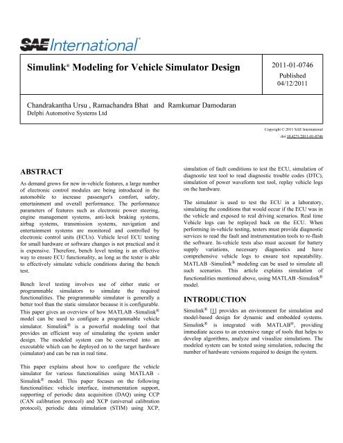
Simulink ® <strong>Modeling</strong> <strong>for</strong> <strong>Vehicle</strong> <strong>Simulator</strong> <strong>Design</strong><br />
Chandrakantha Ursu , Ramachandra Bhat and Ramkumar Damodaran<br />
<strong>Delphi</strong> Automotive Systems Ltd<br />
ABSTRACT<br />
As demand grows <strong>for</strong> new in-vehicle features, a large number<br />
of electronic control modules are being introduced in the<br />
automobile to increase passenger's com<strong>for</strong>t, safety,<br />
entertainment and overall per<strong>for</strong>mance. The per<strong>for</strong>mance<br />
parameters of features such as electronic power steering,<br />
engine management systems, anti-lock braking systems,<br />
airbag systems, transmission systems, navigation and<br />
entertainment systems are monitored and controlled by<br />
electronic control units (ECUs). <strong>Vehicle</strong> level ECU testing<br />
<strong>for</strong> small hardware or software changes is not practical and it<br />
is expensive. There<strong>for</strong>e, bench level testing is an effective<br />
way to ensure ECU functionality, as long as the tester is able<br />
to effectively simulate vehicle conditions during the bench<br />
test.<br />
Bench level testing involves use of either static or<br />
programmable simulators to simulate the required<br />
functionalities. The programmable simulator is generally a<br />
better tool than the static simulator because it is configurable.<br />
This paper gives an overview of how MATLAB -Simulink ®<br />
model can be used to configure a programmable vehicle<br />
simulator. Simulink ® is a powerful modeling tool that<br />
provides an efficient way of simulating the system under<br />
design. The modeled system can be converted into an<br />
executable which can be deployed on to the target hardware<br />
(simulator) and can be run in real time.<br />
This paper explains about how to configure the vehicle<br />
simulator <strong>for</strong> various functionalities using MATLAB -<br />
Simulink ® model. This paper focuses on the following<br />
functionalities: vehicle interface, instrumentation support,<br />
supporting of periodic data acquisition (DAQ) using CCP<br />
(CAN calibration protocol) and XCP (universal calibration<br />
protocol), periodic data stimulation (STIM) using XCP,<br />
simulation of fault conditions to test the ECU, simulation of<br />
diagnostic test tool to read diagnostic trouble codes (DTC),<br />
simulation of power wave<strong>for</strong>m test tool, replay vehicle logs<br />
on the hardware.<br />
The simulator is used to test the ECU in a laboratory,<br />
simulating the conditions that would occur if the ECU was in<br />
the vehicle and exposed to real driving scenarios. Real time<br />
<strong>Vehicle</strong> logs can be replayed back on the ECU. When<br />
per<strong>for</strong>ming in-vehicle testing, testers must provide diagnostic<br />
services to read the fault and instrumentation tools to re-flash<br />
the software. In-vehicle tests also must account <strong>for</strong> battery<br />
supply variations, necessary diagnostics and have<br />
comprehensive vehicle logs to ensure test repeatability.<br />
MATLAB -Simulink ® modeling can be used to simulate all<br />
such scenarios. This article explains simulation of<br />
functionalities mentioned above, using MATLAB -Simulink ®<br />
model.<br />
INTRODUCTION<br />
2011-01-0746<br />
Published<br />
04/12/2011<br />
Copyright © 2011 SAE International<br />
doi:10.4271/2011-01-0746<br />
Simulink ® [1] provides an environment <strong>for</strong> simulation and<br />
model-based design <strong>for</strong> dynamic and embedded systems.<br />
Simulink ® is integrated with MATLAB ® , providing<br />
immediate access to an extensive range of tools that helps to<br />
develop algorithms, analyze and visualize simulations. The<br />
modeled system can be tested using simulation, reducing the<br />
number of hardware versions required to design the system.
Figure 1. Autocoding of Simulink ® Model<br />
A similar principle is also applicable <strong>for</strong> designing the<br />
vehicle simulator used to test automotive electronic controller<br />
units (ECU). The vehicle simulators used to simulate an<br />
automotive environment that can be designed using<br />
Simulink ® . The simulated model can be autocoded using real<br />
time workshop and then built into an executable using C<br />
compiler to run on real time operating system.<br />
Figure 2. Simulink ® Model Distribution on to the<br />
Targets<br />
Opal-RT TestDrive [4] provides the most effective way to<br />
implement a model-based approach to design vehicle<br />
simulation. MATLAB-Simulink ® will allow us to quickly<br />
create real-time simulations of dynamic systems and use them<br />
throughout the design cycle - from initial concepts, to<br />
controller design, test and validation using hardware-in-theloop<br />
(HIL) testing.<br />
The target system is a PC or cluster of PCs where the<br />
simulation runs. The real-time requires a real-time operating<br />
system (RTOS) such as QNX. The target system allows us to<br />
per<strong>for</strong>m model compilation and real-time execution, as well<br />
as scheduling any signal I/O hardware <strong>for</strong> HIL applications.<br />
Figure 3. Test Bench Setup<br />
This paper illustrates the vehicle simulator <strong>for</strong> an adaptive<br />
cruise control (ACC) system. A radar scans the road traffic<br />
conditions and sends this in<strong>for</strong>mation on the CAN bus. These<br />
CAN messages are used by the ACC to per<strong>for</strong>m vehicle<br />
control actions (such as braking and accelerating) depending<br />
on the road traffic conditions.<br />
MATLAB-SIMULINK ® BASED<br />
VEHICLE SIMULATION<br />
Using a MATLAB - Simulink ® model, various simulations<br />
can be per<strong>for</strong>med to verify any ECU functionality at bench<br />
level. This paper explains the following simulations:<br />
1. Network simulation<br />
2. Decoding of CAN messages from the ECU<br />
3. Instrumentation support <strong>for</strong> reading and writing memory<br />
through CAN calibration protocol (CCP) [2] and universal<br />
calibration protocol (XCP) [3]<br />
4. Support <strong>for</strong> periodic data acquisition (DAQ) and periodic<br />
data stimulation (STIM) using CCP and XCP<br />
5. Simulation of fault conditions to test the ECU<br />
6. Simulation of diagnostic test tool to read diagnostic<br />
trouble code (DTC)<br />
7. Simulation of power wave<strong>for</strong>m test tool
8. Replay CAN logs on target hardware <strong>for</strong> functional<br />
verification<br />
9. Test automation using python scripts<br />
10. Message logger<br />
1. NETWORK SIMULATION<br />
Traffic data from the radar, yaw rate sensor, and vehicle<br />
speed sensor are simulated by Simulink ® models.<br />
The radar sensor transmits scan data through a set of CAN<br />
messages periodically. Each set of messages is transmitted<br />
sequentially and the sequence is repeated.<br />
Figure 4. Message Scheduler<br />
Figure 4 shows the simulation of sequences used <strong>for</strong><br />
scheduling radar messages. Each pulse is separated from<br />
other by 2msec. Each of these pulses will trigger set of CAN<br />
messages.<br />
Figure 5. Scheduler on Simulation<br />
Each message also has individual control to simulate missing<br />
message fault diagnostics.<br />
The ACC gets CAN messages from other ECUs such as the<br />
engine management system (EMS), brakes control module<br />
(BCM), transmission control module (TCM) and instrument<br />
cluster (IC). The simulator model groups all these messages<br />
based on the appropriate periodicity, with message triggering<br />
accomplished through the Simulink ® pulse generator.<br />
Messages can employee several methods to maintain data<br />
integrity logic, through scan index, rolling count and<br />
checksum calculations.<br />
Figure 6. Network Simulation<br />
Figure 7. Data Integrity using Rolling Count and<br />
Checksum
Figure 8. Rolling Count on Simulation<br />
Figure 9. Radar Scan Index on Simulation<br />
2. DECODING OF CAN MESSAGES<br />
FROM THE ECU<br />
Decoding of CAN messages is automated in the model with<br />
the help of CAN database.<br />
3. INSTRUMENTATION SUPPORT FOR<br />
READING AND WRITING MEMORY<br />
THROUGH CAN CALIBRATION<br />
PROTOCOL (CCP) AND UNIVERSAL<br />
CALIBRATION PROTOCOL (XCP)<br />
CAN calibration protocol (CCP) provide a set of commands<br />
<strong>for</strong> instrumentation. Read- and-write memory operations are<br />
achieved using UPLOAD and DOWNLOAD commands<br />
respectively.<br />
Universal measurement and calibration protocol (XCP) offers<br />
synchronous data transfer in both directions, from master<br />
(simulator) to slave (ECU) and from slave to master. XCP<br />
protocol uses transportation layers like CAN, TCP/IP, UDP/<br />
IP and USB.<br />
This Simulink ® model uses TCP/IP as a transport layer <strong>for</strong><br />
XCP to verify ACC algorithms which involves processing of<br />
huge amount of data.<br />
Figure 10. CCP Architecture<br />
Figure 11. XCP Architecture<br />
4. SUPPORT FOR PERIODIC DATA<br />
ACQUISITION (DAQ) AND PERIODIC<br />
DATA STIMULATION (STIM) USING<br />
CCP AND XCP<br />
Data acquisition (DAQ) is used to read non-contiguous<br />
memory locations periodically.
Figure 12. DAQ Concept<br />
In Simulink ® , the above concept has been implemented as<br />
follows:<br />
Figure 12a. Simulink ® Implementation of CCP and<br />
DAQ<br />
The Simulink ® model configures the ECU to send periodic<br />
updates of memory (DAQ) through following CCP<br />
commands.<br />
1. SET_DAQ_PTR<br />
2. WRITE_DAQ<br />
3. START_STOP<br />
Figure 12b. Timestamp Check<br />
Figure 12c. Encoding values to DAQ buffer<br />
Figure 12d. Decoding values front DAQ buffer<br />
At this point ECU starts sending DAQ messages on CAN<br />
bus. The simulator receives these messages.<br />
The DAQ buffer update process is executed much faster<br />
(4ms) than the minimum DAQ period (20ms) and hence<br />
needs to check <strong>for</strong> the new timestamp to avoid duplication of<br />
data in DAQ buffer.<br />
This is achieved by comparing the current timestamp with the<br />
last stored timestamp.
5. SIMULATION OF FAULT<br />
CONDITIONS TO TEST THE ECU<br />
Fault simulation can be achieved in the following ways:<br />
1. Missing node faults - by stopping messages from<br />
simulated nodes like ECM, BCM.<br />
2. Missing Scan Fault - by stopping the update of the radar<br />
scan index.<br />
3. Rolling Count (RC) Fault - by stopping the rolling count<br />
increment.<br />
4. Checksum Value Fault - by calculating the wrong<br />
checksum value <strong>for</strong> signals.<br />
5. RC Sliding Window Fault - by sending m wrong RC<br />
frames out of n.<br />
Sliding window logic is achieved using the Simulink ® pulse<br />
generator with varying duty cycles.<br />
Figure 13. Sliding Window <strong>for</strong> Rolling Count<br />
Figure 14. RC Sliding Window on Simulation<br />
6. SIMULATION OF DIAGNOSTIC<br />
TEST TOOL TO READ DIAGNOSTIC<br />
TROUBLE CODE (DTC)<br />
The diagnostic test tool sends a service request over the<br />
vehicle CAN bus to diagnose the ECU.<br />
Diagnostic requests can be of two types, namely<br />
1. Physical diagnostic request<br />
2. Functional diagnostic request<br />
The simulator can be configured <strong>for</strong> global generic diagnostic<br />
specification (GGDS) or non-GGDS type.<br />
Figure 15. Diagnostics Test Tool<br />
Depending on the configuration, the diagnostic request is sent<br />
and the diagnostic response is processed.<br />
The diagnostic response bytes are stored in a buffer based on<br />
the frame index of the response.
Figure 16. Handling of Multi-frame<br />
Figure 17. Decoding DTCs<br />
The faults are simulated from the simulator by various<br />
methods such as stopping messages, sending messages with<br />
error signals set, etc. The ECU sets the diagnostic trouble<br />
codes (DTC) <strong>for</strong> each fault. These fault conditions can be<br />
read from the diagnostic services. Since the ECUs support<br />
30-50 different DTCs, this in<strong>for</strong>mation has to be transmitted<br />
in multiple CAN frames. Since each frame of the DTC<br />
response is transmitted from the ECU, the Simulink ® model<br />
samples these messages and then stores it in buffers.<br />
7. SIMULATION OF POWER<br />
WAVEFORM TEST TOOL<br />
In the vehicle environment, the ECU is subjected to power<br />
variations and it is very important to know how the ECU's<br />
functionality will be affected by such conditions. The<br />
Simulink ® model helps in generating different types of power<br />
wave<strong>for</strong>ms.<br />
Figure 18. Power Wave<strong>for</strong>m Test Setup<br />
Here the requirement is to generate different types of<br />
wave<strong>for</strong>ms. Using the block as follows, different kinds of<br />
wave<strong>for</strong>ms can be generated that will drive the programmable<br />
power supply.<br />
8. REPLAY CAN LOGS ON TARGET<br />
HARDWARE FOR FUNCTIONAL<br />
VERIFICATION<br />
As the vehicle control algorithms <strong>for</strong> various features of<br />
adaptive cruise control grows more complex, simulation of<br />
all real-time scenarios to validate ECU functionality is not<br />
always possible.
Figure 18a. PWTT Simulation<br />
Figure 18b. Portion of PWTT Block<br />
Figure 18c. Various PWTT Wave<strong>for</strong>ms
Figure 19a. Data Playback Setup<br />
Figure 19b. Data logged during playback using DAQ feature of CCP<br />
Figure 19c. <strong>Vehicle</strong> braking and <strong>Vehicle</strong> Speed in<br />
response to Brake
CAN message logs collected from the vehicle are transmitted<br />
back to the ECU by Simulink ® model in real time to verify<br />
the functionally of vehicle control algorithms. During this<br />
activity, the Simulink ® model monitors software variables in<br />
the ECU via the DAQ feature of CCP. Symbol in<strong>for</strong>mation<br />
parameters are read from an A2L file by a python script and<br />
passed to the model.<br />
9. TEST AUTOMATION USING<br />
PYTHON SCRIPTS<br />
Verification of functional test procedures can be automated<br />
with the help of python scripts which establish required<br />
values <strong>for</strong> Simulink ® signals. A set of library modules is<br />
developed with various functions that can be called from<br />
python scripts and can be reused across multiple programs.<br />
Figure 20. Python Scripting Window<br />
10. MESSAGE LOGGER<br />
The Simulink ® model sends raw CAN frames directly to the<br />
host PC through TCP/IP. The message logger decodes and<br />
displays the messages along with their description. This helps<br />
in monitoring CAN traffic <strong>for</strong> debugging.<br />
Figure 21. Message Logger GUI<br />
SUMMARY/CONCLUSIONS<br />
Using Simulink ® , the time required <strong>for</strong> vehicle simulator<br />
modeling can be reduced drastically. Simulation logic can be<br />
verified be<strong>for</strong>e running on target and can be separated from<br />
low level device drivers, making the model less dependent on<br />
the simulator. In this paper, Simulink ® is used to build a<br />
<strong>Vehicle</strong> <strong>Simulator</strong> Model containing basic functionalities <strong>for</strong><br />
effectively testing the ECU, which can be configured based<br />
on the tests required to be per<strong>for</strong>med. With this<br />
programmable simulator, ECU is exposed to real world<br />
driving scenarios in a laboratory environment with the test<br />
cases being written through Python automated scripts. Real<br />
world data in terms of vehicle logs can also be replayed back<br />
into ECU and per<strong>for</strong>mance of various software algorithms<br />
can be easily verified. The model simulates different kinds of<br />
power wave<strong>for</strong>ms to which the ECU is being exposed and the<br />
per<strong>for</strong>mance is analyzed.<br />
REFERENCES<br />
1. MATLAB - Simulink ® Reference & User Guide (http://<br />
www.mathworks.com/)<br />
2. CCP_V2.1.pdf (http://www.asam.net/)<br />
3. ASAM_XCP_Part1-Overview_V1.0.0.pdf (http://<br />
www.asam.net/)<br />
4. Opal-RT TestDrive Manual (http://www.opal-rt.com/<br />
product/testdrive) MATLAB - Simulink ® is a Registered<br />
Trademark of Math Works, Inc. TestDrive is a Registered<br />
Trademark of Opal-RT Technologies.
CONTACT INFORMATION<br />
Chandrakantha Ursu, M.S.<br />
Specialist<br />
Independent Test & Verification - Active Safety<br />
<strong>Delphi</strong> Automotive Systems Pvt. Ltd<br />
Technical Centre India<br />
Kalyani Platina, Block 1, No 24<br />
EPIP Zone Phase II, Whitefield<br />
Bangalore - 560066, India<br />
Phone: 91 80 30777595<br />
chandrakantha.ursu@delphi.com<br />
Ramachandra Bhat K, M.S.<br />
Systems Engineer - Active Safety<br />
<strong>Delphi</strong> Automotive Systems Pvt. Ltd<br />
Technical Centre India<br />
Kalyani Platina, Block 1, No 24<br />
EPIP Zone Phase II, Whitefield<br />
Bangalore - 560066, India<br />
Phone: 91 80 30777801<br />
ramachandra.bhat@delphi.com<br />
Ramkumar Damodaran, B.E.<br />
Technical Leader<br />
Independent Test & Verification - Active Safety<br />
<strong>Delphi</strong> Automotive Systems Pvt. Ltd<br />
Technical Centre India<br />
Kalyani Platina, Block 1, No 24<br />
EPIP Zone Phase II, Whitefield<br />
Bangalore - 560066, India<br />
Phone: 91 80 30777689<br />
ramkumar.damodaran@delphi.com<br />
DEFINITIONS/ABBREVIATIONS<br />
ACC<br />
A2L<br />
BCM<br />
CAN<br />
CCP<br />
DAQ<br />
Adaptive Cruise Control<br />
ASAM MCD 2MC/ASAP2 standard<br />
Brake Control Module<br />
Controller Area Network<br />
CAN Calibration Protocol<br />
Data Acquisition<br />
DLC<br />
DTC<br />
ECM<br />
ECU<br />
GUI<br />
HIL<br />
IC<br />
I/O<br />
PC<br />
Data Length Code<br />
Diagnostic Trouble Code<br />
Engine Control Module<br />
Electronic Control Unit<br />
Graphical User Interface<br />
Hardware In the Loop<br />
Instrument Cluster<br />
Input/Output<br />
Personal Computer<br />
PWTT<br />
Power Wave<strong>for</strong>m Test Tool<br />
QNX<br />
Unix-like real time operating system<br />
RADAR<br />
Radio Detection And Ranging<br />
RC<br />
Rolling Count<br />
RTOS<br />
Real Time Operating System<br />
STIM<br />
Data Simulation<br />
TCP/IP<br />
Transmission Control Protocol/Internet Protocol
XCP<br />
Universal Measurement and Calibration Protocol<br />
UDP/IP<br />
User Datagram Protocol/Internet Protocol<br />
USB<br />
Universal Serial Bus<br />
The Engineering Meetings Board has approved this paper <strong>for</strong> publication. It has<br />
successfully completed SAE's peer review process under the supervision of the session<br />
organizer. This process requires a minimum of three (3) reviews by industry experts.<br />
All rights reserved. No part of this publication may be reproduced, stored in a<br />
retrieval system, or transmitted, in any <strong>for</strong>m or by any means, electronic, mechanical,<br />
photocopying, recording, or otherwise, without the prior written permission of SAE.<br />
ISSN 0148-7191<br />
Positions and opinions advanced in this paper are those of the author(s) and not<br />
necessarily those of SAE. The author is solely responsible <strong>for</strong> the content of the paper.<br />
SAE Customer Service:<br />
Tel: 877-606-7323 (inside USA and Canada)<br />
Tel: 724-776-4970 (outside USA)<br />
Fax: 724-776-0790<br />
Email: CustomerService@sae.org<br />
SAE Web Address: http://www.sae.org<br />
Printed in USA