Simulink® Modeling for Vehicle Simulator Design - Delphi
Simulink® Modeling for Vehicle Simulator Design - Delphi
Simulink® Modeling for Vehicle Simulator Design - Delphi

Create successful ePaper yourself
Turn your PDF publications into a flip-book with our unique Google optimized e-Paper software.
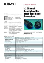
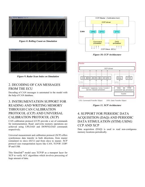
Figure 8. Rolling Count on Simulation<br />
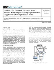
Figure 9. Radar Scan Index on Simulation<br />
2. DECODING OF CAN MESSAGES<br />
FROM THE ECU<br />
Decoding of CAN messages is automated in the model with<br />
the help of CAN database.<br />
3. INSTRUMENTATION SUPPORT FOR<br />
READING AND WRITING MEMORY<br />
THROUGH CAN CALIBRATION<br />
PROTOCOL (CCP) AND UNIVERSAL<br />
CALIBRATION PROTOCOL (XCP)<br />
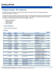
CAN calibration protocol (CCP) provide a set of commands<br />
<strong>for</strong> instrumentation. Read- and-write memory operations are<br />
achieved using UPLOAD and DOWNLOAD commands<br />
respectively.<br />
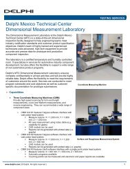
Universal measurement and calibration protocol (XCP) offers<br />
synchronous data transfer in both directions, from master<br />
(simulator) to slave (ECU) and from slave to master. XCP<br />
protocol uses transportation layers like CAN, TCP/IP, UDP/<br />
IP and USB.<br />
This Simulink ® model uses TCP/IP as a transport layer <strong>for</strong><br />
XCP to verify ACC algorithms which involves processing of<br />
huge amount of data.<br />
Figure 10. CCP Architecture<br />
Figure 11. XCP Architecture<br />
4. SUPPORT FOR PERIODIC DATA<br />
ACQUISITION (DAQ) AND PERIODIC<br />
DATA STIMULATION (STIM) USING<br />
CCP AND XCP<br />
Data acquisition (DAQ) is used to read non-contiguous<br />
memory locations periodically.