Simulink® Modeling for Vehicle Simulator Design - Delphi
Simulink® Modeling for Vehicle Simulator Design - Delphi
Simulink® Modeling for Vehicle Simulator Design - Delphi

You also want an ePaper? Increase the reach of your titles
YUMPU automatically turns print PDFs into web optimized ePapers that Google loves.
8. Replay CAN logs on target hardware <strong>for</strong> functional<br />
verification<br />
9. Test automation using python scripts<br />
10. Message logger<br />
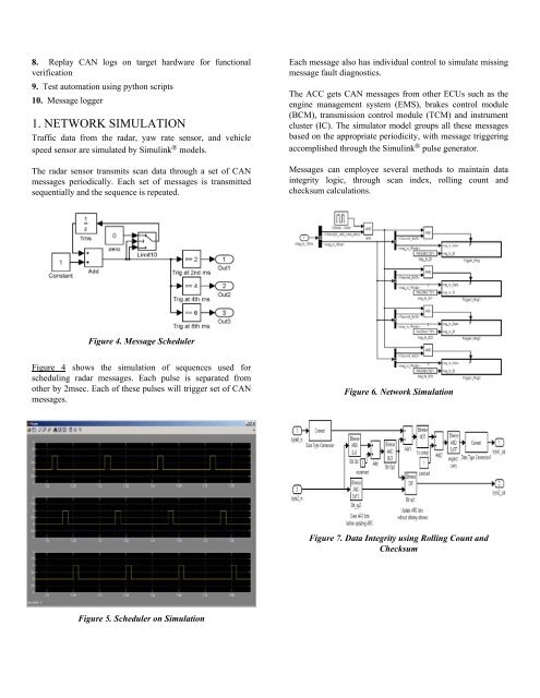
1. NETWORK SIMULATION<br />
Traffic data from the radar, yaw rate sensor, and vehicle<br />
speed sensor are simulated by Simulink ® models.<br />
The radar sensor transmits scan data through a set of CAN<br />
messages periodically. Each set of messages is transmitted<br />
sequentially and the sequence is repeated.<br />
Figure 4. Message Scheduler<br />
Figure 4 shows the simulation of sequences used <strong>for</strong><br />
scheduling radar messages. Each pulse is separated from<br />
other by 2msec. Each of these pulses will trigger set of CAN<br />
messages.<br />
Figure 5. Scheduler on Simulation<br />
Each message also has individual control to simulate missing<br />
message fault diagnostics.<br />
The ACC gets CAN messages from other ECUs such as the<br />
engine management system (EMS), brakes control module<br />
(BCM), transmission control module (TCM) and instrument<br />
cluster (IC). The simulator model groups all these messages<br />
based on the appropriate periodicity, with message triggering<br />
accomplished through the Simulink ® pulse generator.<br />
Messages can employee several methods to maintain data<br />
integrity logic, through scan index, rolling count and<br />
checksum calculations.<br />
Figure 6. Network Simulation<br />
Figure 7. Data Integrity using Rolling Count and<br />
Checksum