Simulink® Modeling for Vehicle Simulator Design - Delphi
Simulink® Modeling for Vehicle Simulator Design - Delphi
Simulink® Modeling for Vehicle Simulator Design - Delphi

You also want an ePaper? Increase the reach of your titles
YUMPU automatically turns print PDFs into web optimized ePapers that Google loves.
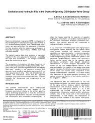
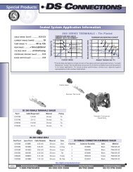
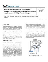
Figure 16. Handling of Multi-frame<br />
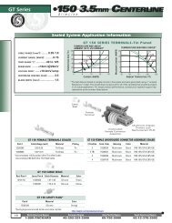
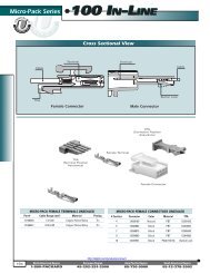
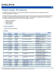
Figure 17. Decoding DTCs<br />
The faults are simulated from the simulator by various<br />
methods such as stopping messages, sending messages with<br />
error signals set, etc. The ECU sets the diagnostic trouble<br />
codes (DTC) <strong>for</strong> each fault. These fault conditions can be<br />
read from the diagnostic services. Since the ECUs support<br />
30-50 different DTCs, this in<strong>for</strong>mation has to be transmitted<br />
in multiple CAN frames. Since each frame of the DTC<br />
response is transmitted from the ECU, the Simulink ® model<br />
samples these messages and then stores it in buffers.<br />
7. SIMULATION OF POWER<br />
WAVEFORM TEST TOOL<br />
In the vehicle environment, the ECU is subjected to power<br />
variations and it is very important to know how the ECU's<br />
functionality will be affected by such conditions. The<br />
Simulink ® model helps in generating different types of power<br />
wave<strong>for</strong>ms.<br />
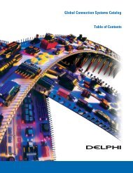
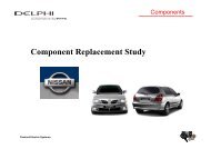
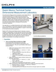
Figure 18. Power Wave<strong>for</strong>m Test Setup<br />
Here the requirement is to generate different types of<br />
wave<strong>for</strong>ms. Using the block as follows, different kinds of<br />
wave<strong>for</strong>ms can be generated that will drive the programmable<br />
power supply.<br />
8. REPLAY CAN LOGS ON TARGET<br />
HARDWARE FOR FUNCTIONAL<br />
VERIFICATION<br />
As the vehicle control algorithms <strong>for</strong> various features of<br />
adaptive cruise control grows more complex, simulation of<br />
all real-time scenarios to validate ECU functionality is not<br />
always possible.