Operators guide v3851-4981 - Vinten Radamec
Operators guide v3851-4981 - Vinten Radamec
Operators guide v3851-4981 - Vinten Radamec

Create successful ePaper yourself
Turn your PDF publications into a flip-book with our unique Google optimized e-Paper software.
Lens serial connection<br />
The lens serial port (9) is not currently utilized.<br />
<strong>Vinten</strong> <strong>Radamec</strong> PDA connection<br />
The <strong>Vinten</strong> <strong>Radamec</strong> PDA configures, calibrates and coordinates all devices connected to the HPM.<br />
Connect the <strong>Vinten</strong> <strong>Radamec</strong> PDA to the PDA Comms port (16) using the supplied PDA cable. For<br />
more information please refer to the <strong>Vinten</strong> <strong>Radamec</strong> PDA <strong>Operators</strong> Guide (Publication Part No.<br />
V4015-4980).<br />
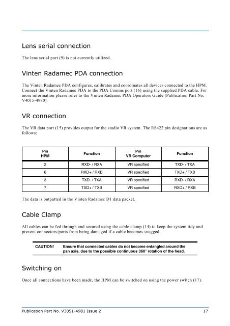
VR connection<br />
The VR data port (15) provides output for the studio VR system. The RS422 pin designations are as<br />
follows:<br />
Pin<br />
HPM<br />
The data is outputted in the <strong>Vinten</strong> <strong>Radamec</strong> D1 data packet.<br />
Cable Clamp<br />
All cables can be fed through and secured using the cable clamp (14) to keep the system tidy and<br />
prevent connectors/ports from being damaged if a cable becomes snagged.<br />
Switching on<br />
Function<br />
Pin<br />
VR Computer<br />
Function<br />
2 RXD- / RXA VR specified TXD- / TXA<br />
6 RXD+ / RXB VR specified TXD+ / TXB<br />
3 TXD- / TXA VR specified RXD- / RXA<br />
7 TXD+ / TXB VR specified RXD+ / RXB<br />
CAUTION! Ensure that connected cables do not become entangled around the<br />
pan axis, due to the possible continuous 360° rotation of the head.<br />
Once all connections have been made, the HPM can be switched on using the power switch (17).<br />
Publication Part No. V3851-<strong>4981</strong> Issue 2 17