Operation manual - Werner Dosiertechnik
Operation manual - Werner Dosiertechnik
Operation manual - Werner Dosiertechnik

Create successful ePaper yourself
Turn your PDF publications into a flip-book with our unique Google optimized e-Paper software.
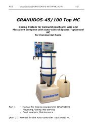
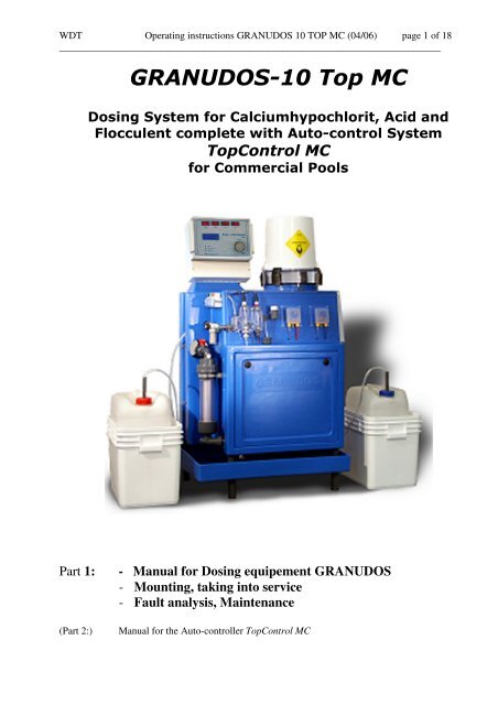
WDT Operating instructions GRANUDOS 10 TOP MC (04/06) page 1 of 18<br />
____________________________________________________________________________<br />
GRANUDOS-10 Top MC<br />
Dosing System for Calciumhypochlorit, Acid and<br />
Flocculent complete with Auto-control System<br />
TopControl MC<br />
for Commercial Pools<br />
Part 1: - Manual for Dosing equipement GRANUDOS<br />
- Mounting, taking into service<br />
- Fault analysis, Maintenance<br />
(Part 2:) Manual for the Auto-controller TopControl MC
WDT Operating instructions GRANUDOS 10 TOP MC (04/06) page 2 of 18<br />
____________________________________________________________________________<br />
Series No.....................................Customer.....................................Date of delivery................…...<br />
Operating Instructions GRANUDOS 10 TOP MC<br />
Safety Devices<br />
1. Chlorine and acid may not be mixed together or<br />
with other chemicals<br />
Pay attention to the safety devices on chemical<br />
Containers<br />
2. Close hopper immediately after filling<br />
3. If an adapter to a chemical container is used the<br />
hopper must be screwed even and firmly to the<br />
container<br />
4. Ensure machine is kept clean. If chemical is spilled,<br />
clean up immediately.<br />
5. Only instructed personnel may work with the<br />
GRANUDOS<br />
6. Ensure booster pump does not run dry, always<br />
isolate pump when backwashing.
WDT Operating instructions GRANUDOS 10 TOP MC (04/06) page 3 of 18<br />
____________________________________________________________________________<br />
TABLE OF CONTENTS<br />
page<br />
1 Function of GRANUDOS Top Control 4<br />
1.1 Data, Measures, Performance 4<br />
1.2 Dosing Assembly Chlorine 5<br />
1.3 Acid dosing 6<br />
1.4 Flocculant dosing 6<br />
1.5 Dissolving System 8<br />
2 The Measuring system 8<br />
2.1 Measuring water flow control 8<br />
2.2 Measuring cell 8<br />
2.2.1 Measuring Free Chlorine 8<br />
2.2.2 Measuring pH-value 9<br />
2.2.3 Redox Tension 9<br />
2.2.4 Temperature 9<br />
2.3 Test water take off 9<br />
2.4 Test cylinder for redox tension 9<br />
2.5 Test and cleaning chemicals 9<br />
3 Installation 10<br />
3.1 Mounting the machine 10<br />
3.2 Tubing 10<br />
3.3 Electrical Connection 11<br />
4 Start up operation 11<br />
4.1 Setting the operation and dosing parameters 11<br />
4.2 Deaeration of water supply tubing 11<br />
4.3 Adjusting the measuring water flow 11<br />
4.4 Water level in flushing tank 11<br />
4.5 Pressure switch booster pump 11<br />
4.6 Water flow / Suction performance of the venturi 11<br />
4.7 Filling of Chlorine into hopper 12<br />
4.7.1 Standard hopper 5 kg 12<br />
4.7.2 Filling with adapter for 10 kg bin 12<br />
4.8 Dosing pumps for acid and flocculant 12<br />
5. Calibration of the measuring systems 12<br />
5.1 Calibration pH-value 13<br />
5.2 Calibration of Free Chlorine 13<br />
5.3 Check of Redox Tension 13<br />
6. Faults and Alarm identification and problems solving 13<br />
6.1 Faults indicated by monitoring switches 14<br />
6.2 Input switches to start special programmes 15<br />
6.3 Soft ware alarms 15<br />
6.4 Faults not indicated by monitoring 15<br />
7 Maintenance – taking out of operation 16<br />
7.1 GRANUDOS function 16<br />
7.2 Measuring Technics 17<br />
7.2.1 Chlorine electrodes 17<br />
7.2.2 pH-electrode 17<br />
7.2.3 Redox electrode 17<br />
7.3 Taking out of operation 17<br />
8 Spare parts GRANUDOS Top MC 18
WDT Operating instructions GRANUDOS 10 TOP MC (04/06) page 4 of 18<br />
____________________________________________________________________________<br />
1. The Functions of GRANUDOS 10 TOP:<br />
The features:<br />
- Measuring free chlorine , pH-value, redox tension, temperature<br />
- Big red value displays<br />
- 4-lines-display for service guide, operated by 1 selection turn key<br />
Control and monitoring of all operational functions<br />
- Proportional dosing control<br />
- Dosing of chlorine granulate from hopper 5 kg or directly from 10 kg bin<br />
- Control Dosing of dry chlorine by measuring free chlorine or redox<br />
- Acid dosing by a peristaltic pump included<br />
- Dosing of flocculant by a peristaltic pump<br />
- Filter backwash disinfection<br />
- Shock chlorination programmable<br />
- Night program with reduced set points for free chlorine and flocculant<br />
- Filling a buffer tank with chlorine solution to disinfect other small pools by additional<br />
dosing pumps (optional)<br />
- Interface RS485 to link a computer, printer, Mobil SMS or mimic . * optional from 7/06<br />
- fault remote control (non volt)<br />
- Mimic (optional)<br />
1.1 Data, Measures, Performance<br />
Dosing performance:<br />
chlorine: 0.5 kg/h, optional 2,5 kg/h<br />
motor 12rpm, optional 50 rpm<br />
acid: 1,0 l/h, optional 2,0 l/h<br />
dosing hose 3,2x1,6, opt. 4,8x1,6<br />
flocculant 105 ml/h with dosing hose<br />
0,8x1,6<br />
Measures:<br />
base: 71 x 52 cm<br />
height: 130 cm<br />
weight: 40 kg<br />
Material:<br />
PE, polyethylene<br />
control housing ABS IP54<br />
Booster Pump<br />
centrifugal pump: SS - 0.3 kW, 230 volt 1ph<br />
supply pressure: minimum 0,1 – 1,2 bar<br />
counter pressure: 0 – 1,2 bar<br />
(depending on supply pressure)<br />
water flow: app. 1000 l/h<br />
Fault remote indication by relay
WDT Operating instructions GRANUDOS 10 TOP MC (04/06) page 5 of 18<br />
____________________________________________________________________________<br />
1.2 Dosing Assembly dry chlorine<br />
The dosing assembly, placed into the main housing consists of the dosing hopper (5a) and the dosing unit<br />
with dosing motor (6a), the dosing screw (6c) fitted together and pushed into and screwed to the motor<br />
holder (6b). The dosing nozzle (6d) is heated to eliminate condensation of the warm pool water vapour. The<br />
dosing unit is screwed into the dosing hopper.<br />
The required dosing rate is adjusted at the control board by means of a dosing cycle and dosing time. The<br />
solenoid knocker acting at each dosing prevents bridging of the chemical in the hopper<br />
5a dosing hopper<br />
5b hopper lid<br />
6a dosing motor<br />
6b motor holder<br />
6c dosing screw<br />
6d heated dosing nozzle<br />
6e knocker<br />
The knocker (6e) gives a stroke to the dosing<br />
hopper wall and thus prevents clogging of the<br />
chemical.<br />
The complete dosing assembly can be taken out of<br />
the frame for service. Fitting systems as shown<br />
below allow chemical containers of 10 kg to be fitted directly to the hopper reducing the handling required<br />
ie. the chemical does not need to be transferred from the container to the hopper by hand using a scoop.<br />
Fitting system to join a Fitting system to join a<br />
10 kg container with round edge 10 kg HTH container
WDT Operating instructions GRANUDOS 10 TOP MC (04/06) page 6 of 18<br />
____________________________________________________________________________<br />
The dosing is principally as to the following scheme:<br />
max. dosing time chlorine max dosing time acid actual dosing<br />
time<br />
Dosing is always in the first 30 seconds of the set dosing cycle adjustable from 30 seconds to 10<br />
minutes. Between chlorine and acid dosing there is always a pause of at least 3.5 seconds ensuring<br />
dosing of both chemicals never occurs.<br />
The actual dosing time for the chlorine and acid dosing motor is calculated by the processor as to<br />
the proportional gap between the actual and set values.<br />
1.3 Acid Dosing<br />
30 seconds<br />
The acid required either for pH-control and for cleaning of the<br />
flushing, mixing and dosing system is metered by the peristaltic<br />
pump to the flushing water via the dosing injector (11). As the<br />
cleaning procedure is vital for the correct function of the<br />
complete dosing assembly, chlorine dosing is stopped if the<br />
level switch on the supply carboy lance indicates container<br />
empty.<br />
As acid use one on base of sulphuric acid (37 – 50 %),please do<br />
not use concentrated hydrochloric acid for this job as that<br />
penetrates the peristaltic hose and will destroy the pump head.<br />
Diluted hydrochloric acid may be not strong enough for the<br />
neutralisation job. Please note that using dry acid (sodium<br />
bisulphate) 20% (= maximum concentration) is equivalent to a<br />
only 10% sulphuric acid.<br />
Maximum dosing performance is app. 3 l/h and is set as for<br />
chlorine. The dosing cycle set for chlorine is valid for acid too.<br />
1.4 Flocculant dosing<br />
dosing cycle<br />
Adjustable from 30 seconds to 10 minutes<br />
For the dosing of the flocculant the same type of peristaltic pump is used as for acid but is rpmcontrolled<br />
ensuring a continuous chemical flow is achieved, which is important for best performance<br />
of the flocculant.<br />
The dosing performance is set in the menu by setting the circulation rate of the filter system in m³/h<br />
and the specific dosing rate of the chemical in ml/m³ of circulation. The dosing of flocculant works<br />
independent of the function of measuring/dosing of chlorine/acid.
WDT Operating instructions GRANUDOS 10 TOP MC (04/06) page 7 of 18<br />
____________________________________________________________________________<br />
1.5 Dissolving System<br />
7<br />
10<br />
11<br />
9<br />
7 pressure switch 13 venturi nozzle<br />
8 floating valve 14 orifice washer<br />
9 booster pump Lo 2HMS3 15 level switch low/high<br />
10 flow switch holder with flow switch 16 lid on flushing tank<br />
11 acid dosing valve with chlorine dust protection<br />
12 mixing and dissolving 17 overflow to drain<br />
chamber with PVC ball valve<br />
The supply water coming from the pool circulation from behind filter (minimum pressure 0,2 bar) is divided<br />
at the discharge of the booster pump (9), one way leading to the flushing tank via the floating valve (8), the<br />
other branch directed to the venturi nozzle (13), where the flushing water is sucked together with the dosed<br />
chemicals out of the flushing tank. (A third way possibly goes as measuring water directly to the measuring<br />
cell). A flow switch (10), being installed in the suction tube of the venturi monitors the suction power of the<br />
venturi. To adjust the suction to different pressure conditions an orifice washer (13c) with different bores<br />
can be used. To mix the chemicals and to ensure the complete dissolving of the chlorine granules a cyclone<br />
mixing chamber (12) is fitted after the venturi.<br />
To ensure that calcium hypochlorite and acid do not come into contact with each other in the open part of<br />
the dissolving assembly a sophisticated control system is installed:<br />
- metering of the two chemicals is regulated with pauses between the metering intervals<br />
- dosing motors of chlorine and acid are controlled by connected relays – joint dosing is<br />
- impossible<br />
- flow switch (10 indicates if water flow to venturi falls below 150 – 200 l/h<br />
- level switch (14) indicates water maximum or water minimum level in the flushing tank thus<br />
supervising water supply conditions.<br />
If any non-compliance with the given limits occurs, the chemical dosing will be stopped, the fault is<br />
shown on the display.<br />
16<br />
14<br />
13<br />
12<br />
8<br />
17<br />
15
WDT Operating instructions GRANUDOS 10 TOP MC (04/06) page 8 of 18<br />
____________________________________________________________________________<br />
2. The measuring system<br />
The measuring water flow system consists of<br />
- tubing connection with ball valve (1)<br />
- filter (3)<br />
- water flow control (5)<br />
- measuring electrodes cell (11)<br />
2.1 measuring water flow control<br />
The measuring of free chlorine is dependent of the measuring water flow through<br />
the cell and must be controlled therefore within a range of +/- 10-20% of the set<br />
value. The switch bobbin (10a) of the flow monitoring switch must be at top and<br />
the blue cleaning glass beads in the chlorine measuring cell must rotate effectively.<br />
2.2 Measuring cell<br />
The measuring cell is fabricated of transparent PMMA and consists of three parts:<br />
- flow control cell with temperature sensor<br />
- Measuring cell for free chlorine<br />
- Measuring cell for pH-value and redox tension<br />
The measuring water flow is monitored by a reed switch. The<br />
flow bobbin (10a) is pushed upwards in the flow control cell to<br />
the temperature sensor fitted into the top of the flow control cell.<br />
The reed sensor is fitted simple pushed behind the temperature<br />
sensor in the flow cell. At low flow – the switch bobbin goes<br />
down in the bore, “meas. water low ” is indicated at the display<br />
and dosing is stopped.<br />
When the Granudos is stopped to avoid uncontrolled water flow through the<br />
open measuring cell a spring loaded stop valve is fitted into the inlet union of<br />
the measuring cell holding app. 0,7 bar supply pressure.<br />
2.2.1 Measuring Free Chlorine<br />
The measuring method for free chlorine functions to the potentiostatic principle: The<br />
active gold electrode is loaded via a reference electrode by a certain potential at which<br />
the chlorine chemical reaction on the gold surface is optimised, the influence of the<br />
reaction of other chemicals on the gold is minimised. So a stable and reliable<br />
proportional measuring current is achieved at a very stable situation at the zero chlorine<br />
point<br />
ER Reference electrode<br />
EA working gold electrode<br />
EG counter electrode<br />
I measuring current<br />
U Potential on<br />
reference electrode
WDT Operating instructions GRANUDOS 10 TOP MC (04/06) page 9 of 18<br />
____________________________________________________________________________<br />
The active gold electrode consists of a gold round piece and is fitted within a stainless steel body<br />
which is working as the counter electrode, the measuring current flows between these two electrodes.<br />
This assembly is screwed from the bottom into the measuring cell. Blue glass beads moved by the<br />
measuring water are cleaning the surface of the gold electrode. The Ag/AgCl reference electrode is<br />
screwed from top.<br />
By using 3 separate electrodes for the system a high measuring stability is achieved and separation<br />
makes cost effective replacements in the future.<br />
2.2.2 pH-Value<br />
The pH-electrode is screwed from top of the combination cell for<br />
pH-value and redox.<br />
2.2 3 Redox Tension<br />
The redox tension is the relevant value to judge the hygienic state of the pool<br />
water. It is indicating the relation between the red-uctiv forces (organic chemicals)<br />
and the ox-idising forces (free chlorine) in the water. The relevant potential is<br />
built up on the surface of the platinum electrode and is measured against the reference<br />
electrode of the pH-electrode as a tension (mV). The higher the redox tension is, the<br />
quicker any micro organisms are killed. The platinum surface of the electrode is<br />
cleaned by glass beads as the gold electrode<br />
As the redox tension is very dependent on the free chlorine and the pH-value it can be<br />
used very well to monitor these measurements.<br />
2.2.4 Temperature<br />
For temperature measuring a digital sensor is used and it also acts as a distance holder for the<br />
flow sensor as well.<br />
2.3 Test water take off<br />
At the outlet of the pH/redox cell the measuring water is flowing free out via a short hose to a<br />
tube connected to the flushing tank of the GRANUDOS. The measuring water goes back to the<br />
circulation. At this hose the test water to control the water quality by test reagents can be taken.<br />
2.4 Test cylinder for redox tension<br />
For testing the redox system a test cylinder is fixed at the front right besides the measuring cell. The<br />
redox electrode is screwed in, test buffer is filled to the cylinder, the pH-electrode is put in from top<br />
and you can read the resulting redox tension at the display. See programme “Redox test”.<br />
2.5 Test and cleaning chemicals<br />
The test and cleaning chemicals for the electrodes are found on the left side of the GRANUDOS<br />
housing<br />
- buffer solution pH 4,0 50 ml<br />
- buffer solution pH 7,0 50 ml<br />
- buffer solution Ag/AgCI - Pt 475 mV 50 ml<br />
- cleaning liquid (diluted hydrochloric acid) 50 ml<br />
- glass beads to clean the platinum and gold electrode
WDT Operating instructions GRANUDOS 10 TOP MC (04/06) page 10 of 18<br />
____________________________________________________________________________<br />
3. Installation<br />
3.1 Mounting the machine<br />
pack out the machine, lay down ist with the backside on zhe floor and support it at the lower part by<br />
about 5 cm. Now screw in the 4 feet with the screws on 1 side and female thread at the other into the<br />
moulded nuts in the bottom of the housing, do not turn them tight. Now adjust the tub to the 4 feet and<br />
fix it with the other 4 feet by screwing them through the bores in the tub. Then turn the machine up and<br />
settle it and the previewed place.<br />
3.2 Tubing – please see installation diagram<br />
For satisfactory water flow through the dissolving system the supply pressure must be at least 0,2 bars. At<br />
low service pressure the counter pressure must be low, too. Counter pressure and pressure loss in the dosing<br />
line should be as low as possible. At works the GRANUDOS has been tested at following pressure<br />
conditions:<br />
Service pressure 1,2 bars Counter pressure 1,2 bars<br />
0,6 bars 0,8 bars<br />
0,3 bars 0,5 bars<br />
Within these ranges the GRANUDOS should function well. In addition please pay attention to the<br />
following:<br />
1. Tapping point for supply water to be before filter. Minimum pressure 2 mwg.. Measuring water<br />
supply directly from the booster pump or by an extra tapping point. In this case block the measuring<br />
water tapping above the booster pump by the attached PVC stopper 3/8”<br />
2. Dosing point after heat exchanger - a non return valve must be installed in the dosing tube.<br />
3. Ensure that the tapping/dosing points are free flowing and not blocked by scale or corrosion.<br />
4. Pipe runs to be kept as short as possible. PVC-tubing 25 mm or hose 1´´. For longer distances or<br />
poor pressure conditions use bigger tubing. If hoses are used do not kink them !!<br />
5. Piping should not go up and down as there could be formed “air bags” in the tubing preventing<br />
free water flow with consequently damage of the pump – especially at taking into operation.<br />
6. Use high quality PVC ball valves ¾”.<br />
7. If mounted above pool level please install non return valves into the supply and dosing tube, the<br />
latter spring loaded (0,3-0,5 bar) to prevent self empying of the flushing system<br />
Ballance<br />
tank<br />
circulation<br />
pump<br />
Main pool<br />
Filter<br />
Heat<br />
exchanger<br />
Dissolving water<br />
(measuring water)<br />
acid<br />
Measuring water<br />
pump<br />
Chlorine<br />
Acid<br />
GRANUDOS - TOP<br />
Autocontrol system for<br />
free chlorine, pH, ORP<br />
temperature<br />
Chemical dosing<br />
dry chlorine, acid<br />
flocculant<br />
chlorine<br />
flocculant
WDT Operating instructions GRANUDOS 10 TOP MC (04/06) page 11 of 18<br />
____________________________________________________________________________<br />
3.3 Electrical connection<br />
The electrical supply of the GRANUDOS has to be controlled by the electrical supply of the circulation<br />
pumps that dosing can only take place with water circulation and accordingly water supply to<br />
GRANUDOS. The GRANUDOS has to be stopped at back washing, too! See wiring diagram<br />
To connect external systems to the GRANUDOS please use only flexible cable type as attached<br />
Electrical works are only to be executed by authorised people.<br />
3.4 Flocculant<br />
If the GRANUDOS Top is supplied with the flocculant pump fit the injection valve ½” to the tapping point<br />
as far as possible before the filter directly before or behind the circulation pump. Do not kink the tubing. If<br />
it happens, use a new one!<br />
4. Start<br />
After piping is finished, open the ball valves at the tapping points and at GRANUDOS. Press floater of<br />
floating valve inside the tank down to let water flow into the flushing tank. When the flushing tank is half<br />
full switch on the GRANUDOS mains, the booster pump of GRANUDOS should not run dry.<br />
4.1 Setting the operation and dosing parameters<br />
Take the attached list of settings and work through all settings as indicated. We recommend to write down<br />
all settings in this list for further discussions if needed.<br />
To ensure correct dosing of the chemicals water flow through the flushing tank and measuring cell must run<br />
in the correct way as described below, otherwise you get faults indication and no function..<br />
Please note, that this start procedure must be executed at every new start<br />
after a longer stop of operation to prevent interruptions and pump failures<br />
4.2 Deaeration of the water supply tubing<br />
When switching on the GRANUDOS take care to deaerate the supply water tubing completely. For this<br />
please observe the water level inside the pre-filter. If it get’s empty switch off the pump/machine and wait<br />
till the filter is full again, then switch on again. On operation the filter must be and stay full of water; a little<br />
air at top staying steadily does not matter. The deaeration procedure can take some minutes depending on<br />
the length of the supply tubing.<br />
4.3 Adjusting measuring water flow<br />
the flow is adjusted so that the switch bobbin in the flow monitoring is pushed up and the glass beads are<br />
rotating effectively in the chlorine as in the pH/redox cell. If measuring water is too low and the switch<br />
bobbin falls down, “meas. water low” is indicated at the display and dosing is switched off.<br />
4.4 Water level in the flushing tank<br />
Water level in the tank should be maintained at half full. To obtain a higher level unscrew float rod, for a<br />
lower level screw in the float rod. One turn gives about 1 cm in height.<br />
4.5 Pressure switch booster pump<br />
The installed pressure switch has a switch point at 1,5 bar to protect the pump against cavitation. If no<br />
supply pressure or air is in the supply tubing, the pump will be switched off.<br />
4.6 Water flow/Suction performance of the venturi<br />
At stable water level the switch bobbin of the flow switch inside the suction tube (10) should definitely<br />
have risen up to the top, the control lamp of the switch may not burn.<br />
To adjust the water flow to the pressure conditions of the filter system a nozzle is inserted in the union (13c)<br />
behind the venturi. If water level in the tank tends to run low or if switch bobbin is at top without pump<br />
running (too high suction at the venturi – high pressure difference between tapping points ) fit the nozzle<br />
with the 5,5 mm diameter hole you find in the spare parts kit. If the water level tends to run high and/or<br />
suction is too low – switch bobbin does not rise (too high counter pressure?) put in the 7 mm nozzle or use<br />
without nozzle.
WDT Operating instructions GRANUDOS 10 TOP MC (04/06) page 12 of 18<br />
____________________________________________________________________________<br />
4.7 Filling of chlorine into the hopper<br />
4.7.1 Filling standard hopper 5 kg without adapter<br />
Before carrying out any task involving chemicals the operator should put an personal protective equipment<br />
to provide adequate protection to eyes, respiratory orifices, hands and clothing.<br />
- Lid of control box is closed. Open the chlorine hopper lid.<br />
- Fill the chlorine into the hopper carefully to the hopper wall with help of a scoop from the drum<br />
minimising any dusting up of the chemical.<br />
- Add only the consumption of chlorine for app. 2 weeks.<br />
- After filling the hopper carefully cover the lid of the chemical drum again.<br />
- Close the hopper lid.<br />
-<br />
4.7.2 Filling with adapter HTH 10 kg drum<br />
Put new drum in front and screw off the lid. Lift out the empty hopper from the GRANUDOS housing and<br />
put it with the drum to floor. Fix the drum with your legs and turn the hopper off the drum. If chemical rests<br />
in the “empty” drum pour it carefully to the “full” drum. Now screw carefully the hopper onto the new drum<br />
that the curl fits well together. Take the full drum with the hopper, turn it and put it into the GRANUDOS<br />
housing that the cable is behind in the hole on backside and the bolt of the hopper in front in the hole.<br />
4.8 Acid and flocculant dosing pumps<br />
The acid dosing pump (red mark, red dosing tube) and the flocculant dosing pump (blue mark, blue dosing<br />
tube) mounted front panel of the housing is delivered with loose dosing hose to prevent deformation on<br />
stock time. Push the hose holder into the shaped form of the housing and the hose back into the yellow<br />
housing. Turn the roller (half round to outside) clockwise some times so that the hose is situated evenly<br />
back in the housing. Then push the safety disc on the shaft and the pump cover – both in the small bag<br />
attached above the pump. Position the chemical containers within their safety tubs beside the GRANUDOS,<br />
open and put the suctions lances marked red and blue into them.<br />
As acid use one on base of sulphuric acid (37 – 50 %). Do not use concentrated hydrochloric acid as this<br />
will damage the peristaltic pump.<br />
5. Calibration of the measuring systems<br />
Pump housing<br />
Roller<br />
Safety disc<br />
Dosing hose<br />
Hose holder with tube<br />
conn. 4x1:<br />
suction<br />
pressure<br />
attention<br />
the hose must not<br />
be twisted<br />
For calibration a code no. must not be used. Please work through the displayed advises. Here some general<br />
remarks.<br />
Even the measuring systems are working very stable, the characteristics of sensors are changing with time.<br />
By daily checks the measuring quality is monitored.<br />
Please note, that the chemical check kits monitoring measures are not exact, that there are systems faults of<br />
about +/- 0.2 at pH-Value and +/- 0,05-0.1 mg/l at free chlorine possible. So calibration should only be done<br />
after repeated and higher deviation, especially not at low values.
WDT Operating instructions GRANUDOS 10 TOP MC (04/06) page 13 of 18<br />
____________________________________________________________________________<br />
5.1 Calibration of pH-Electrode<br />
There are 2 calibration programmes offered by the TopControl system:<br />
- Quick calibration only by using the phenol red indication – calib only within +/- 0.2 pH<br />
- Full calibration programme by the 2 buffer solutions pH 7,0 and 4,0 – normally used<br />
Worked through by the operators guide at the display. Please note, that the phenol red check has a systems<br />
fault of +/- 0,2. Only the full calibration will indicate the true pH-value – provided that the buffer solutions<br />
are ok.<br />
5.2 Calibration of free chlorine<br />
There are 2 calibration programmes offered by the TopControl system:<br />
- Quick calibration by using the DPD 1 indication – normally used<br />
- calibration zero point<br />
Please note following guide lines. Calibration only if the DPD-check daily before the begin of pools<br />
opening:<br />
:<br />
- At several days there is a deviation in the same direction<br />
- More than 0,1 - 0,15 mg/I shows with several checks<br />
- Not too low values shown, at least 0,3 mg/l<br />
Calibration only in the morning before opening the pool when all circulation water has the same quality.<br />
With high bathers load and maybe poor hydraulics in the pool the values can change rapidly and calibration<br />
can lead to bad results. If calibration seems necessary please calibrate only a half of the deviation and check<br />
again next morning.<br />
Please note that the measuring fault with DPD is 0,05-0,1 mg/l . At a low free chlorine value of e.g. 0,2 mg/l<br />
the relative fault would be 25-50 % ! After coming up again with the free chlorine to 1 mg/l, the real free<br />
chlorine value could be then from 0,5 – 2 mg/l<br />
5.3 Check of redox tension<br />
At normal pool operation the indicated values of free chlorine, pH and redox are in an equilibrium, they<br />
show always the same relation. With free chlorine 0,3-0,6 and a pH of 7,0-7,4 the redox indicated should be<br />
about 720-780 mV. This actual values depend on fresh water quality and efficiency of the pool water<br />
treatment, but they stay constant. As the indicated values of free chlorine and pH are controlled, they stay<br />
very constant. If redox indication changes this is an indication for changes in real values of free chlorine or<br />
pH or there is a change in the water treatment, e.g. flocculation, bad backwashing, etc. So first check the<br />
free chlorine and pH and if they are ok than check the redox as shown in the programme. If this is ok too<br />
check your water treatment.<br />
If there are inconsistencies mostly the fault is at the pH-electrode even it can be calibrated normally. The<br />
platinum electrode normally is very stable<br />
6. Faults and alarm identification and problems solving<br />
All faults catched by a switch or sensor input as all value alarms are identified and shown at the display in<br />
the 3 rd line. Here is only the 1 st fault shown. Following faults are shown in a listing after “click” on the<br />
cursor before the fault indication. As all switches at the GRANUDOS 10 are normally open a fault is clearly<br />
indicated by the (1) at the end of the line indicating “closed”. In the line is also indicated on what connector<br />
the switch is connected.<br />
The faults or alarms must stay for at least 6 seconds to be recognised. If a fault/alarm vanishes itself, the<br />
Granudos starts again automatically. If a switch obviously is faulty and stops function, you can start the<br />
machine by disconnecting the faulty switch, but see for a new one as this function is now not monitored.
WDT Operating instructions GRANUDOS 10 TOP MC (04/06) page 14 of 18<br />
____________________________________________________________________________<br />
6.1 Faults indicated by monitoring switches<br />
Flow meas-w<br />
Flow switch for measuring water indicates too low flow. Flow switch bobbin is not on top.<br />
Increase flow, clean pre-filter and screens in the chlorine and pH-cell. Adjust water flow.<br />
Empty Cl 2<br />
In the GRANUDOS 10 the chlorine hopper empty switch is not installed. Switch input bridged.<br />
Empty pH<br />
Acid container indicates empty. Change container to a full one. Possibly switch is faulty<br />
Empty flocc<br />
Flocculant container empty. Replace container with a full one. Possibly switch is faulty<br />
Pressure GR<br />
Pressure of supply water to GRANUDOS is too low. Granudos stops.<br />
When taking into operation the supply pressure is really too low. From works the switch pressure is fixed to<br />
1.5 bar. At normal supply conditions the pump should reach this pressure. If not water supply tubing is shut,<br />
air is in the tubing, pre-filter blocked.<br />
Suction low<br />
Suction power of venturi is not enough: switch bobbin of flow switch in suction tube is at bottom of tube.<br />
By pressing the connecting hose from tank to the suction tube the bobbin does not move, switch LED burns.<br />
- At installation: service pressure too low – counter pressure too high. tubing faulty or too<br />
small: take out orifice washer (13c) from union behind venturi.<br />
- Booster pump performance too low – see pressure limits at para 3. “Installation – piping”.<br />
Fit the supplied pressure gauge to inlet and outlet to check pressure situation.<br />
- Particles inside venturi or at outlet nozzle of flushing tank (high possibility after installation)<br />
- Suction tube and/or mixing cyclone are turbid by calcium: acid dosing too low:<br />
If there is still a little suction this can be easily cleaned by pouring hydrochloric acid into<br />
the suction cone of the tank.<br />
Level high<br />
Water level in the flushing tank high. There is more water coming into the tank than is sucked away by the<br />
venturi.<br />
If suction power of venturi is O.K. switch bobbin of flow switch in suction tube is at top of tube. By<br />
pressing the supply hose to the suction tube the bobbin goes down and switch LED burns. If loosened again,<br />
bobbin goes up quickly and switch LED goes out.<br />
In this case there should be a fault in the floating valve: check whether by moving the floater slowly up and<br />
down the incoming water flow decreases or increases steadily. If so adjust water level by turning the floater<br />
rod one turn right. If floating valve does not work steadily, fit a new valve diaphragm.<br />
If suction is not sufficient, see above at “Suction low”<br />
level low<br />
water level in the flushing tank is low.<br />
- Suction power too high: fit an orifice washer of 5,5 mm inside union behind venturi.<br />
- Supply water tubing is blocked<br />
- Floating valve to tank is blocked, diaphragm faulty<br />
Cl 2 missing<br />
chlorine missing switch is indicating at the program “buffer tank filling” no dosing chlorine. GRANUDOS<br />
switches off as obviously there is a problem at the chlorine dosing technics.
WDT Operating instructions GRANUDOS 10 TOP MC (04/06) page 15 of 18<br />
____________________________________________________________________________<br />
6.2 Software alarms<br />
There are only allowed ranges for the setting of alarm levels depending on the set points. Some alarms can<br />
be deactivated by setting a “0” instead of a value in the settings windows.<br />
At soft ware alarms principally check the water figures free and combined chlorine and pH. If the shown<br />
values are not correct, first calibrate / check the electrodes .<br />
Redox high Indication for high free chlorine or good water quality.<br />
If free chlorine indication at the display is high too, reduce dosing<br />
performance of chlorine and/or set higher redox alarm level.. See<br />
for better sampling water take off point. If chlorine indication is<br />
normal at set point, check free chlorine by DPD method and adjust<br />
the measuring system.<br />
Check pH – may be too low – see para. 6.3<br />
Redox low Indication for low free chlorine or poor water quality<br />
If free chlorine indication at the display is low too:<br />
- fault on chlorine dosing technics<br />
- check output voltage, test dosing by activating output for<br />
chlorine dosing motor<br />
- check pH – may be too high – see para. 6.3<br />
Chlorine high - Chlorine dosing motor output faulty, dosing whereas set point is<br />
surpassed – use new electronic plate<br />
- poor hydraulics in the pool can leed to uneven distribution of<br />
chlorine to the sampling water. Reduce dosing performance at<br />
increased basic dosing<br />
Chlorine low - fault on chlorine dosing technics<br />
- check output voltage, test dosing by activating output for<br />
chlorine dosing motor dosing screw blocked or loose, heated<br />
dosing nozzle blocked.<br />
- poor hydraulics in the pool, clouds without chlorine coming to<br />
measuring water take out - increase dosing performance at<br />
increased basic dosing<br />
pH high acid dosing motor output or dosing pump/hose faulty.<br />
: check dosing function of acid pump by selecting test program for<br />
acid pump. If pump runs, see whether an air bubble is sucked to<br />
pump, if not examine the pump roller and pump hose. If all is OK,<br />
choose lower set point for pH<br />
pH low - acid dosing motor output faulty, dosing whereas set point is<br />
surpassed – use new electronic plate<br />
6.3 Faults not indicated by monitoring switches<br />
Overflow from tank too much at switch off of GRANUDOS<br />
- switch bobbin of flow switch blocked on top situation<br />
- sealing of switch bobbin faulty<br />
- membrane of floating valve faulty<br />
- supply pressure of an external booster pump too high<br />
- set in spring-loaded check valve in ell of floating valve. Please make sure that because of<br />
pressure drop you will need a pressure of at least 0,4 bar.
WDT Operating instructions GRANUDOS 10 TOP MC (04/06) page 16 of 18<br />
____________________________________________________________________________<br />
7 Maintenance<br />
It is strongly recommended that a regular maintenance programme is undertaken. Consult your<br />
installer/supplier and take up a service/maintenance agreement. This way the machine will be<br />
maintained in good operating condition. The machine should be serviced at least once a year.<br />
7.1 GRANUDOS functions<br />
Minimum checks include the following items:<br />
- maintain the environment of the machine clean<br />
- clean strainer if necessary – a poluted filter causes cavitation and consequently damage of the<br />
booster pump.<br />
For cleaning take out the complete filter and clean the filter insert outside.<br />
- pay attention to any noise of the pump: cavitation, bearings – if so, contact your supplier<br />
- check monthly for the acid pump whether the springs are o.k. If corrosion can be seen, change<br />
the dosing hose. In any case change it once per year.<br />
- monthly or with each new drum/filling up check function of all sensors i.e. water flow, level and<br />
empty switches<br />
- every 2 months clean the chlorine dosing screw: dismantle the hopper and take out dosing motor<br />
with the screw, clean with a brush – do not use water<br />
- change membrane of floating valve once per year<br />
- change seal of flow switch bobbin every ½ year<br />
- check once per year acid dosing valve – change seals
WDT Operating instructions GRANUDOS 10 TOP MC (04/06) page 17 of 18<br />
____________________________________________________________________________<br />
7.2 Measuring technics<br />
7.2.1 Chlorine electrodes - Changing and cleaning<br />
The chlorine sensor itself is the gold electrode (8a) with the contact tube. It<br />
is fitted into the stainless steel electrode holder ¾“ (8b) with a flat joint<br />
(8c). for cleaning or change if worn :<br />
- Pull out the push connector down and place it to the side to<br />
prevent water entering connectors.<br />
- Screw out the electrode holder (8b) from the cell.<br />
- Screw out the pressure screw ½“ (8d)<br />
- Now take the isolated contact tube and pull it out<br />
- clean the electrode with alcohol and electrode cleaner<br />
Attention! The electrode cleaning liquid is a light acid<br />
Before fitting the gold electrode clean and dry it well<br />
Fit a new flat gasket and fill than the cavety with cleaning glass beads.<br />
To change the reference electrode undo screw connector and place it to side that it does not get wet. A<br />
cleaning of the electrode is technically not necessary. In any situation do not wipe over the diaphragm<br />
to avoid scaling<br />
7.2.2 pH-electrode<br />
- At any circumstance avoid moisture getting into the connection of the electrode. The electrode<br />
will not function.<br />
- Pay attention, that there is no air in the bottom part of the inner electrode. Remove air by shaking<br />
it like a medical thermometer.<br />
7.2.3 Redox- electrode<br />
Attention! New electrodes are to be calibrated before taken into service<br />
The redox-electrode is fabricated the same as the chlorine electrode<br />
7.3 Taking out of service<br />
- disconnect acid dosing hose (or use a new one at starting again)<br />
- empty the dosing hopper, take out chlorine dosing screw, clean it thoroughly and store it at a dry<br />
place<br />
- clean all parts of GRANUDOS thoroughly, empty all water containing parts as measuring cell,<br />
pump, filter, mixing cyclon<br />
- leave the GRANUDOS switched on – use program status “off”<br />
- clean the environment of the machine thoroughly.<br />
If there is no risk of frost keep the electrodes within the cell.
WDT Operating instructions GRANUDOS 10 TOP MC (04/06) page 18 of 18<br />
____________________________________________________________________________<br />
8. Spare Parts GRANUDOS 10 Top<br />
Designation Item No.<br />
Chlorine dosing dosing hopper 5 kg 12798<br />
cover for dosing hopper GR 10 12353<br />
dosing motor PLG 30-12 rpm 13811<br />
motor holder PLG- d25 11541<br />
dosing screw d6/D19 GR10 12320<br />
dosing nozzle heated GR 11556<br />
knocker GR 10 complete 12868<br />
Acid dosing acid pump Sa complete 11628<br />
pump housing Sa 12702<br />
roller Sa 12609<br />
dosing hose 3.2x1,6 Sa 12782<br />
supply carbuoy lance 12523<br />
acid injection valve GR 11633<br />
repair set for acid valve 11636<br />
Flocculant pump dosing hose 0,8x1,6Ph-Sa<br />
other pump parts identically to acid pump<br />
13482<br />
Filter filter housing d75 GR 12746<br />
filter top with PVC ball valve d25 12304<br />
O-ring filter GR 11258<br />
cover control box GR10 10796<br />
Floating valve floating valve d25 GR10 complete 12916<br />
membrane for floating valve 11619<br />
floater 11621<br />
level switch GR/PAK 10496<br />
Booster pump booster pump Lo 2HMS3-A 10657<br />
slide ring seal complete -A 12800<br />
Flow switch<br />
assembly<br />
flow switch holder GR ½´´ – S14 US 12729<br />
flow switch GR/PAK ind. 18x1 11603<br />
flow switch bobbin ind. ½´´US 12730<br />
seal ring Vi 14/9 flow switch bobbin 11090<br />
connecting tube Si 10/2,5/180 11565<br />
Venturi venturi ½” GR/PAK complete 11792<br />
orifice washer for venturi 11594<br />
venturi-nozzle ½´´ 12306<br />
venturi-body with connector ½´´ 12305<br />
Cyclon mixing cyclon GR 10 Top 13778<br />
Control system measuring / basic plate TopControl MC 18104<br />
controller plate TopControl MC 18105<br />
Power plate TopControl 15083<br />
cover lid to Top Control 13779<br />
Electrodes pH-electrode 10933<br />
chlorine-electrode ¾” gold insert with seal 17957<br />
reference/counter electrode TopControl MC 17179<br />
redox-electrode ½” complete. 11984